EP2175521B1 - Niedrigprofilantenne - Google Patents
Niedrigprofilantenne Download PDFInfo
- Publication number
- EP2175521B1 EP2175521B1 EP09172236A EP09172236A EP2175521B1 EP 2175521 B1 EP2175521 B1 EP 2175521B1 EP 09172236 A EP09172236 A EP 09172236A EP 09172236 A EP09172236 A EP 09172236A EP 2175521 B1 EP2175521 B1 EP 2175521B1
- Authority
- EP
- European Patent Office
- Prior art keywords
- antenna
- cone
- ground plane
- shaped
- antenna element
- Prior art date
- Legal status (The legal status is an assumption and is not a legal conclusion. Google has not performed a legal analysis and makes no representation as to the accuracy of the status listed.)
- Not-in-force
Links
- 239000004020 conductor Substances 0.000 claims description 5
- 230000005855 radiation Effects 0.000 description 6
- 230000001413 cellular effect Effects 0.000 description 5
- 239000002184 metal Substances 0.000 description 4
- 229910052751 metal Inorganic materials 0.000 description 4
- 230000005404 monopole Effects 0.000 description 4
- 238000000034 method Methods 0.000 description 2
- 230000003071 parasitic effect Effects 0.000 description 2
- 230000001681 protective effect Effects 0.000 description 2
- 238000003466 welding Methods 0.000 description 2
- RYGMFSIKBFXOCR-UHFFFAOYSA-N Copper Chemical compound [Cu] RYGMFSIKBFXOCR-UHFFFAOYSA-N 0.000 description 1
- 238000004891 communication Methods 0.000 description 1
- 229910052802 copper Inorganic materials 0.000 description 1
- 239000010949 copper Substances 0.000 description 1
- 238000005520 cutting process Methods 0.000 description 1
- 230000000694 effects Effects 0.000 description 1
- 238000004519 manufacturing process Methods 0.000 description 1
- 238000012986 modification Methods 0.000 description 1
- 230000004048 modification Effects 0.000 description 1
Images



Classifications
-
- H—ELECTRICITY
- H01—ELECTRIC ELEMENTS
- H01Q—ANTENNAS, i.e. RADIO AERIALS
- H01Q9/00—Electrically-short antennas having dimensions not more than twice the operating wavelength and consisting of conductive active radiating elements
- H01Q9/04—Resonant antennas
- H01Q9/30—Resonant antennas with feed to end of elongated active element, e.g. unipole
- H01Q9/40—Element having extended radiating surface
-
- H—ELECTRICITY
- H01—ELECTRIC ELEMENTS
- H01Q—ANTENNAS, i.e. RADIO AERIALS
- H01Q21/00—Antenna arrays or systems
- H01Q21/28—Combinations of substantially independent non-interacting antenna units or systems
Definitions
- the field of the invention relates to radio frequency antenna and more particularly to antenna that operate in a number of different non-harmonically related frequencies.
- Digital wireless systems such as wireless local area networks, or cellular devices, such as cellular telephones may exist in a number of different frequency bands and may each use a unique communication protocol.
- cellular and GSM telephones may operate in the 750-960 MHz frequency band
- PCS and UMTS may operate in a 1700-2170 MHz frequency band
- WIFI may operate in the 2.4-5.8 GHz bands.
- cellular, PCS, UMTS, and WIFI are often used with different types of devices, each with a different functionality and data processing capability. Because of the different functionality, it is often necessary for service providers to provide simultaneous infrastructure access under each of the different protocols.
- the patch may be conventional or include one or more slots for high frequency operation.
- the monopole antenna While, the use of the monopole and patch antenna is effective in some cases, the monopole antenna often experiences a phase reversal at high frequencies resulting in an elevation pattern split of a radiated signal. In addition where the patch antenna structure exceeds 1 ⁇ 4 wavelength in high band frequencies, the radiated field has significant azimuth pattern distortion. Accordingly, a need exists for better antenna that operate in multiple non-harmonically related frequency bands.
- US4074268 discloses an antenna having a metal cone mounted above a ground plane and modular fins and shorting posts mounted between the ground plane and a distal end of the metal cone.
- W02007/048258 discloses an antenna array that includes a radiating element with different bodies - a truncated cone, a ball section and a cylinder - that are physically and electrically coupled together.
- a multi-band antenna that operates in at least two non-harmonically related frequency bands, such antenna comprising: a ground plane; a cone-shaped high frequency antenna element with a tip of the high frequency antenna element disposed adjacent to but electrically isolated from the ground plane with a base of the cone-shaped antenna element extending away from the ground plane; and at least three low frequency antenna elements electrically connected to and extending between the base of the cone-shaped antenna element and the ground plane, wherein the high frequency antenna element and the low frequency antenna elements form a unitary antenna formed from a single flat sheet of conductive material.
- Ultra-wide-band (UWB) antennas have become more important in recent times because of the continued expansion of the use of portable devices. While UWBs are important, they are often difficult to integrate into many living or work spaces because of the height of such devices. However, it is difficult to lower the profile due to a number of fundamental limitations described in a number of references. Typically, the height of a UWB is on the order of about 1 ⁇ 4 wavelength of the lowest operating frequency.
- the increased size of the radiating elements has caused increased UWB pattern distortion for a number of different reasons.
- the increased size causes phase reversal resulting in an elevation pattern split similar to that seen in many prior art dipole antenna.
- an asymmetric bulky radiating structure is provided that typically exceeds 1 ⁇ 4 wavelength in the high band, causing azimuth pattern distortion.
- Mars Antenna provides an antenna with a single PCB inside.
- the single PCB has the advantage of low cost, but with increased pattern distortion.
- Another antenna provide by Mars Antenna provides two quarter-wave monopoles disposed adjacent each other with a height of about 0.16 wavelength. While this antenna is adequate in some applications, it lacks bandwidth.
- ESA electrically small antennas
- the Chu-Wheeler-McLean limitations For example, the expected bandwidth (or Q) versus profile of an ESA can be evaluated using the Chu-Wheeler-McLean limitations.
- FIG. 1a-b depicts a low profile, wide-band antenna 10 shown generally in accordance with an illustrated embodiment of the invention.
- FIG. 1a shows the antenna 10 with a protective cover 12.
- FIG. 1b is a side perspective view of the antenna 10 without the cover 12.
- FIG. 2a is a side view of the antenna 10 and
- FIG. 2b is a cut-away view of the antenna 10 along lines A-A.
- the antenna 10 includes a cone-shaped antenna element 14 disposed proximate the ground plane 12. As shown in FIG. 2b , a tip I 8 the cone-shaped element 14 is disposed adjacent the ground plane 12 with a base 20 extending away from the ground plane 12 orthogonal to the ground plane 12.
- a proximate end of the cone-shaped element 14 is electrically isolated from the ground plane 12.
- the tip 18 is electrically connected to an RF supply cable 22.
- FIGs. 1 and 2 show the cable connected to the tip 18 of the cone-shaped element 14, it should be appreciated that the tip 18 may be truncated to allow a conductor of the cable 22 to penetrate the tip 18 of cone-shaped element 14 for a better connection.
- the connection with the cable 22 may be with a frustum of the cone-shaped element 14.
- the cone-shaped antenna element 14 also includes a set of at least three secondary antenna elements 16.
- the secondary antenna elements 16 function to electrically connect a distal or base end of the cone-shaped antenna element 14 to the ground plane 12.
- the secondary antenna elements also function to mechanically support the cone-shaped element 14.
- the cone-shaped element 14 and secondary antenna elements 16 form a unitary antenna formed from a single flat sheet of conductive metal (e.g., copper).
- the flat piece of metal may be die cut as shown in FIG. 3 .
- a pie shaped portion may be removed by the die cutting process and opposing edges 24, 26 pulled together 28.
- the opposing edges 24, 26 may by joined by any appropriate method (e.g., welding, folding, etc.) to form a hollow cone.
- the secondary elements 16 may be folded downwards to form the supports 16 shown in FIGs. 1, 2 and 3 .
- the distal ends of the secondary elements 16 may be electrically and mechanically joined to the ground plane 12 by another appropriate method (e.g., welding, riveting, etc.).
- the cone-shaped element 14 may have a point contact on the proximal end with an antenna connection of the cable 22 adjacent the ground plane 12 and an annular cross-section parallel to the ground plane 12 with a diameter that diverges in a direction extending away from the ground plane. Opposing sides of the cone-shaped element 14 define a 45 degree angle.
- the cone shaped antenna element 14 may have a total height measured perpendicular to the ground plane of 5 cm (1.97 inches).
- the diameter of the base of the cone-shaped antenna element 14 is approximately 10cm (3.95 inches).
- the legs to ground provide a number of different functionalities.
- the secondary elements 16 may function as radiating elements.
- the secondary elements 16 operate in a parallel resonant mode.
- the symmetric arrangement of the secondary elements 16 cancel the horizontal moments and maintain the conical pattern of the antenna 10.
- the number of grounding legs (secondary antenna elements 16) affect the antenna profile as well as the radiation pattern.
- a symmetric arrangement is preferred for a more uniform azimuth pattern.
- Three secondary antenna elements 16 are shown in FIGs. 1 and 2 for a minimum profile while keeping the rotational symmetry.
- a set of parasitic elements 30 may be added to reduce the ripple in the upper frequency ranges.
- the parasitic elements 30 are electrically isolated from the ground plane 12.
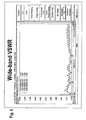
- FIG. 5 is a VSWR chart for the antenna 10 in the frequency range between 698 MHz and 8.5 GHz. As may be noted, the antenna 10 has a VSWR of less than 1.7 over the entire frequency range of from 698 MHz to 8.5 GHz.
- the antenna 10 provides a lower relative profile than conventional antenna with a height at the low frequency limit of 698 MHz of no more than one-eight wavelength.
- the impedance of the antenna 10 remains substantially above a lower limit of-10dB over the entire bandwidth of 698 MHz to 8.5 GHz.
- the Chu-Wheeler-McLean equations may be used to calculate a predicted bandwidth (BW) of the claimed antenna using a diameter of 10cm (3.95 inches) and a frequency of 698 MHz.
- BW predicted bandwidth
- the Chu-Wheeler-McLean equations suggests that the claimed antenna should have a bandwidth of no greater than 5.25:1. Instead the claimed antenna has been demonstrated to have a bandwidth of 12:1.
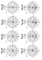
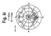
- FIGs. 6a-i are elevation views of far field radiation patterns from 700 MHz to 6.0 GHz. As can be seen, the azimuth far field patterns at 698 MHz are substantially symmetric as would be expected from the symmetry along an antenna axis orthogonal to the ground plane.
- FIGs. 7a-i are elevation views of far field radiation patterns from 700 MHz to 6.0 GHz. As can be seen, the azimuth far field patterns at 6.0 GHz are substantially symmetric as would also be expected from the symmetry orthogonal to the ground plane.
- base 20 of the antenna 10 may be used to support a patch antenna 32.
- the antenna 32 is a global positioning system (GPS) active antenna module.
- GPS global positioning system
- a cable (not shown) for the antenna 32 may extend from the ground plane 12 to the base 20 and antenna 32 along one of the secondary antenna elements 16 so that there is no interference to the radiation pattern.
Landscapes
- Waveguide Aerials (AREA)
Claims (9)
- Mehrbereichsantenne (10), die in mindestens zwei Frequenzbändern arbeitet, die zueinander in keinem harmonischen Verhältnis stehen, die Antenne (10) umfassend:eine Massefläche (12);ein kegelförmiges Hochfrequenz-Antennenelement (14), wobei die Spitze (18) des Hochfrequenz-Antennenelements (14) benachbart zu der Massefläche (12) angeordnet ist, jedoch elektrisch von der Massefläche (12) isoliert ist, und sich die Basis (20) des kegelförmigen Antennenelements (14) entfernt von der Massefläche (12) erstreckt; undmindestens drei Niederfrequenz-Antennenelemente (16), die sich zwischen der Basis (20) des kegelförmigen Hochfrequenz-Antennenelements (14) und der Massefläche (12) erstrecken und elektrisch mit der Basis und der Massefläche verbunden sind,wobei das Hochfrequenz-Antennenelement (14) und die Niederfrequenz-Antennenelemente (16) eine Antenne in einem Stück bilden, die aus einer einzigen ebenen Tafel aus leitendem Material hergestellt wird.
- Mehrbereichsantenne (10) nach Anspruch 1, wobei sich das kegelförmige Hochfrequenz-Antennenelement (14) weg von der Spitze (18) im Wesentlichen unter einem Winkel von fünfundvierzig Grad erstreckt.
- Mehrbereichsantenne (10) nach Anspruch 1 oder 2, die im Querschnitt eine Höhe hat, die im Wesentlichen gleich einem Achtel der Wellenlänge bei einer Betriebsfrequenz von 8,5 GHz ist.
- Mehrbereichsantenne (10) nach irgendeinem vorhergehenden Anspruch, wobei die mindestens drei Niederfrequenz-Antennenelemente (16) zudem einen Abstand von 120 Grad entlang des Umfangs der Basis (20) einnehmen.
- Mehrbereichsantenne (10) nach irgendeinem vorhergehenden Anspruch, ferner umfassend eine Planarantenne (32), die innerhalb der Basis (20) des kegelförmigen Antennenelements (14) angeordnet ist.
- Mehrbereichsantenne (10) nach irgendeinem vorhergehenden Anspruch, wobei die Spitze (18) des kegelförmigen Antennenelements (14) zudem einen Anschluss (22) für ein Koaxialkabel umfasst.
- Mehrbereichsantenne (10) nach irgendeinem vorhergehenden Anspruch, die dafür ausgelegt ist, dass sie in einem Frequenzbereich zwischen 700 MHz und 8,5 GHz arbeitet.
- Mehrbereichsantenne (10) nach irgendeinem vorhergehenden Anspruch, wobei die einzige ebene Tafel aus leitendem Material gestanzt ist.
- Mehrbereichsantenne (10) nach Anspruch 8, wobei die einzige ebene Tafel aus leitendem Material gefaltet wird, um die drei Niederfrequenz-Antennenelemente (16) gegenüber dem kegelförmigen Hochfrequenz-Antennenelement (14) anzuordnen.
Applications Claiming Priority (1)
| Application Number | Priority Date | Filing Date | Title |
|---|---|---|---|
| US12/246,961 US8184060B2 (en) | 2008-10-07 | 2008-10-07 | Low profile antenna |
Publications (2)
| Publication Number | Publication Date |
|---|---|
| EP2175521A1 EP2175521A1 (de) | 2010-04-14 |
| EP2175521B1 true EP2175521B1 (de) | 2012-04-18 |
Family
ID=41478782
Family Applications (1)
| Application Number | Title | Priority Date | Filing Date |
|---|---|---|---|
| EP09172236A Not-in-force EP2175521B1 (de) | 2008-10-07 | 2009-10-05 | Niedrigprofilantenne |
Country Status (4)
| Country | Link |
|---|---|
| US (1) | US8184060B2 (de) |
| EP (1) | EP2175521B1 (de) |
| CN (1) | CN101714691B (de) |
| AT (1) | ATE554513T1 (de) |
Cited By (1)
| Publication number | Priority date | Publication date | Assignee | Title |
|---|---|---|---|---|
| CN111969300A (zh) * | 2020-07-30 | 2020-11-20 | 西南电子技术研究所(中国电子科技集团公司第十研究所) | 微带阵列盘锥复合共形天线 |
Families Citing this family (32)
| Publication number | Priority date | Publication date | Assignee | Title |
|---|---|---|---|---|
| DE102011113725A1 (de) * | 2011-09-17 | 2013-03-21 | Volkswagen Aktiengesellschaft | Mehrbereichsantenne für ein Kraftfahrzeug |
| US8681052B2 (en) | 2011-10-04 | 2014-03-25 | Blaupunkt Antenna Systems Usa, Inc. | Low profile wideband antenna |
| US8994594B1 (en) | 2013-03-15 | 2015-03-31 | Neptune Technology Group, Inc. | Ring dipole antenna |
| US9431712B2 (en) | 2013-05-22 | 2016-08-30 | Wisconsin Alumni Research Foundation | Electrically-small, low-profile, ultra-wideband antenna |
| US9634396B2 (en) * | 2013-07-09 | 2017-04-25 | Galtronics Corporation Ltd. | Extremely low-profile antenna |
| US9692136B2 (en) * | 2014-04-28 | 2017-06-27 | Te Connectivity Corporation | Monocone antenna |
| US20160043472A1 (en) * | 2014-04-28 | 2016-02-11 | Tyco Electronics Corporation | Monocone antenna |
| US9337540B2 (en) | 2014-06-04 | 2016-05-10 | Wisconsin Alumni Research Foundation | Ultra-wideband, low profile antenna |
| EP3002826B1 (de) | 2014-07-03 | 2024-04-17 | Swisscom AG | Antennenvorrichtung |
| CN111048889B (zh) * | 2014-07-17 | 2025-02-11 | 胡贝尔和茹纳股份公司 | 天线装置 |
| CN104157959A (zh) * | 2014-08-08 | 2014-11-19 | 电子科技大学 | 双频宽带电小天线 |
| US9673536B2 (en) | 2015-02-05 | 2017-06-06 | Laird Technologies, Inc. | Omnidirectional antennas, antenna systems and methods of making omnidirectional antennas |
| TWI583053B (zh) | 2015-03-25 | 2017-05-11 | 啟碁科技股份有限公司 | 天線及複合天線 |
| US9680215B2 (en) * | 2015-07-21 | 2017-06-13 | Laird Technologies, Inc. | Omnidirectional broadband antennas including capacitively grounded cable brackets |
| US10074909B2 (en) | 2015-07-21 | 2018-09-11 | Laird Technologies, Inc. | Omnidirectional single-input single-output multiband/broadband antennas |
| EP3375043B1 (de) * | 2015-11-09 | 2021-08-18 | Wiser Systems, Inc. | Ultrabreitband (uwb)-antennen und zugehöriges gehäuse für uwb-antennen |
| AU2016102459A4 (en) * | 2015-12-09 | 2021-04-29 | Licensys Australasia Pty Ltd | An antenna |
| TWI628862B (zh) * | 2016-05-10 | 2018-07-01 | 啟碁科技股份有限公司 | 通訊裝置 |
| US10523306B2 (en) | 2016-08-23 | 2019-12-31 | Laird Technologies, Inc. | Omnidirectional multiband symmetrical dipole antennas |
| US10270162B2 (en) | 2016-09-23 | 2019-04-23 | Laird Technologies, Inc. | Omnidirectional antennas, antenna systems, and methods of making omnidirectional antennas |
| US10819027B1 (en) | 2016-10-12 | 2020-10-27 | Maxtena, Inc. | Wideband multiple-input multiple-output antenna array with tapered body elements |
| US10498047B1 (en) * | 2017-09-20 | 2019-12-03 | Pc-Tel, Inc. | Capacitively-coupled dual-band antenna |
| US10483640B1 (en) * | 2018-12-31 | 2019-11-19 | King Saud University | Omnidirectional ultra-wideband antenna |
| USD891404S1 (en) * | 2019-01-28 | 2020-07-28 | King Saud University | Omnidirectional ultra-wideband antenna |
| US10411357B1 (en) * | 2019-01-28 | 2019-09-10 | Kind Saud University | Ultra-wideband unipole antenna |
| USD889445S1 (en) * | 2019-01-28 | 2020-07-07 | King Saud University | Omnidirectional multiband antenna |
| USD890145S1 (en) | 2019-01-29 | 2020-07-14 | King Saud University | Ultra-wideband unipole antenna |
| WO2021020599A1 (ko) * | 2019-07-26 | 2021-02-04 | 엘지전자 주식회사 | 안테나를 구비하는 전자 기기 |
| WO2021054494A1 (ko) * | 2019-09-19 | 2021-03-25 | 엘지전자 주식회사 | 차량에 탑재되는 광대역 안테나 |
| US12046799B2 (en) | 2019-09-30 | 2024-07-23 | Lg Electronics Inc. | Cone antenna assembly |
| CN116526144B (zh) * | 2023-06-02 | 2026-04-24 | 深圳市塞防科技有限公司 | 一种超宽带全向天线及侦测设备 |
| US20250062538A1 (en) * | 2023-08-17 | 2025-02-20 | Bae Systems Information And Electronic Systems Integration Inc. | Additively manufactured antenna with inverted hat monopole element |
Family Cites Families (12)
| Publication number | Priority date | Publication date | Assignee | Title |
|---|---|---|---|---|
| US3967276A (en) | 1975-01-09 | 1976-06-29 | Beam Guidance Inc. | Antenna structures having reactance at free end |
| US4074268A (en) * | 1976-06-21 | 1978-02-14 | Hoffman Electronics Corporation | Electronically scanned antenna |
| JP2630007B2 (ja) | 1990-03-27 | 1997-07-16 | 日産自動車株式会社 | 平板パッチアンテナ |
| DE19711990C2 (de) | 1997-03-14 | 1999-02-11 | Siemens Ag | Hochspannungsanlage mit einer Vorrichtung zur Übertragung von Signalen |
| US6608600B2 (en) * | 2001-05-03 | 2003-08-19 | Radiovector U.S.A., Llc | Single piece element for a dual polarized antenna |
| US7190318B2 (en) * | 2003-03-29 | 2007-03-13 | Nathan Cohen | Wide-band fractal antenna |
| CN2653716Y (zh) * | 2003-08-18 | 2004-11-03 | 黎萍 | 一种吸顶式移动通讯天线 |
| WO2007048258A1 (de) | 2005-10-27 | 2007-05-03 | Huber+Suhner Ag | Antennenanordnung mit einer breitband-monopol-antenne |
| CN1976120B (zh) * | 2006-12-15 | 2011-04-27 | 陈晖� | 亮灯式双宽频全向吸顶灯天线 |
| CN200983400Y (zh) * | 2006-12-15 | 2007-11-28 | 陈晖� | 亮灯式双宽频全向吸顶灯天线 |
| CN200986968Y (zh) * | 2006-12-22 | 2007-12-05 | 陈晖� | 低轮廓双宽频全向吸顶天线 |
| US7671817B2 (en) * | 2007-02-27 | 2010-03-02 | Sony Ericsson Mobile Communications Ab | Wideband antenna |
-
2008
- 2008-10-07 US US12/246,961 patent/US8184060B2/en active Active
-
2009
- 2009-10-05 AT AT09172236T patent/ATE554513T1/de active
- 2009-10-05 EP EP09172236A patent/EP2175521B1/de not_active Not-in-force
- 2009-10-09 CN CN200910204301.5A patent/CN101714691B/zh active Active
Cited By (1)
| Publication number | Priority date | Publication date | Assignee | Title |
|---|---|---|---|---|
| CN111969300A (zh) * | 2020-07-30 | 2020-11-20 | 西南电子技术研究所(中国电子科技集团公司第十研究所) | 微带阵列盘锥复合共形天线 |
Also Published As
| Publication number | Publication date |
|---|---|
| CN101714691A (zh) | 2010-05-26 |
| US8184060B2 (en) | 2012-05-22 |
| CN101714691B (zh) | 2014-12-24 |
| US20100085264A1 (en) | 2010-04-08 |
| EP2175521A1 (de) | 2010-04-14 |
| ATE554513T1 (de) | 2012-05-15 |
Similar Documents
| Publication | Publication Date | Title |
|---|---|---|
| US8184060B2 (en) | Low profile antenna | |
| CN109149131B (zh) | 偶极天线和相关的多频带天线 | |
| US8866689B2 (en) | Multi-band antenna and methods for long term evolution wireless system | |
| US7385563B2 (en) | Multiple antenna array with high isolation | |
| US9680514B2 (en) | Methods for reducing near-field radiation and specific absorption rate (SAR) values in communications devices | |
| EP2081256B1 (de) | Antennenvorrichtung | |
| EP2154752B1 (de) | Mehrband-Deckenantenne | |
| US8547289B2 (en) | Multimode antenna structure | |
| JP2005198270A (ja) | 超広帯域用の3次元無指向性アンテナ | |
| US6967631B1 (en) | Multiple meander strip monopole antenna with broadband characteristic | |
| EP2437348B1 (de) | Verzweigte UWB-Antenne | |
| US7443350B2 (en) | Embedded multi-mode antenna architectures for wireless devices | |
| US10374311B2 (en) | Antenna for a portable communication device | |
| EP3460906A1 (de) | Antenne eines drahtlostelekommunikationsnetzwerks | |
| EP1947737A1 (de) | Omnidirektionale Dipol-Antenne mit hohem Gewinn | |
| Salim et al. | Multiband Meander UWB Bowtie Antenna with Six Rejection Bands | |
| Antoniades et al. | A compact monopole antenna with a defected ground plane for multi-band applications | |
| Daraghma | Design of Microstrip Patch H-Notch Antenna for Vehicle Using Array Systems | |
| Sharma et al. | Dual band microstrip-fed printed antennas for wireless applications | |
| Tripathi et al. | Design and Simulation of an Elliptical Cylinderbased Patch Antenna for Multiband Wireless Communication | |
| Ge et al. | A dual-band monopole antenna for mobile communications | |
| Baud et al. | Securing a critical infrastructure | |
| Syrytsin et al. | Phased Array Configuration Study for 5G Mobile Terminals | |
| Sayad et al. | A Double Crescent Slots Circular Ultra-Wideband Monopole Antenna for 5G, MBAN/WBAN and Future Internet of Things Applications | |
| Banozic et al. | Dual band planar folded monopole |
Legal Events
| Date | Code | Title | Description |
|---|---|---|---|
| PUAI | Public reference made under article 153(3) epc to a published international application that has entered the european phase |
Free format text: ORIGINAL CODE: 0009012 |
|
| AK | Designated contracting states |
Kind code of ref document: A1 Designated state(s): AT BE BG CH CY CZ DE DK EE ES FI FR GB GR HR HU IE IS IT LI LT LU LV MC MK MT NL NO PL PT RO SE SI SK SM TR |
|
| 17P | Request for examination filed |
Effective date: 20101006 |
|
| 17Q | First examination report despatched |
Effective date: 20101102 |
|
| GRAP | Despatch of communication of intention to grant a patent |
Free format text: ORIGINAL CODE: EPIDOSNIGR1 |
|
| GRAS | Grant fee paid |
Free format text: ORIGINAL CODE: EPIDOSNIGR3 |
|
| GRAA | (expected) grant |
Free format text: ORIGINAL CODE: 0009210 |
|
| AK | Designated contracting states |
Kind code of ref document: B1 Designated state(s): AT BE BG CH CY CZ DE DK EE ES FI FR GB GR HR HU IE IS IT LI LT LU LV MC MK MT NL NO PL PT RO SE SI SK SM TR |
|
| REG | Reference to a national code |
Ref country code: GB Ref legal event code: FG4D |
|
| REG | Reference to a national code |
Ref country code: CH Ref legal event code: EP |
|
| REG | Reference to a national code |
Ref country code: IE Ref legal event code: FG4D |
|
| REG | Reference to a national code |
Ref country code: AT Ref legal event code: REF Ref document number: 554513 Country of ref document: AT Kind code of ref document: T Effective date: 20120515 |
|
| REG | Reference to a national code |
Ref country code: DE Ref legal event code: R096 Ref document number: 602009006387 Country of ref document: DE Effective date: 20120614 |
|
| REG | Reference to a national code |
Ref country code: NL Ref legal event code: VDEP Effective date: 20120418 |
|
| REG | Reference to a national code |
Ref country code: AT Ref legal event code: MK05 Ref document number: 554513 Country of ref document: AT Kind code of ref document: T Effective date: 20120418 |
|
| LTIE | Lt: invalidation of european patent or patent extension |
Effective date: 20120418 |
|
| PG25 | Lapsed in a contracting state [announced via postgrant information from national office to epo] |
Ref country code: PL Free format text: LAPSE BECAUSE OF FAILURE TO SUBMIT A TRANSLATION OF THE DESCRIPTION OR TO PAY THE FEE WITHIN THE PRESCRIBED TIME-LIMIT Effective date: 20120418 Ref country code: NO Free format text: LAPSE BECAUSE OF FAILURE TO SUBMIT A TRANSLATION OF THE DESCRIPTION OR TO PAY THE FEE WITHIN THE PRESCRIBED TIME-LIMIT Effective date: 20120718 Ref country code: CY Free format text: LAPSE BECAUSE OF FAILURE TO SUBMIT A TRANSLATION OF THE DESCRIPTION OR TO PAY THE FEE WITHIN THE PRESCRIBED TIME-LIMIT Effective date: 20120418 Ref country code: FI Free format text: LAPSE BECAUSE OF FAILURE TO SUBMIT A TRANSLATION OF THE DESCRIPTION OR TO PAY THE FEE WITHIN THE PRESCRIBED TIME-LIMIT Effective date: 20120418 Ref country code: SE Free format text: LAPSE BECAUSE OF FAILURE TO SUBMIT A TRANSLATION OF THE DESCRIPTION OR TO PAY THE FEE WITHIN THE PRESCRIBED TIME-LIMIT Effective date: 20120418 Ref country code: IS Free format text: LAPSE BECAUSE OF FAILURE TO SUBMIT A TRANSLATION OF THE DESCRIPTION OR TO PAY THE FEE WITHIN THE PRESCRIBED TIME-LIMIT Effective date: 20120818 Ref country code: LT Free format text: LAPSE BECAUSE OF FAILURE TO SUBMIT A TRANSLATION OF THE DESCRIPTION OR TO PAY THE FEE WITHIN THE PRESCRIBED TIME-LIMIT Effective date: 20120418 |
|
| PG25 | Lapsed in a contracting state [announced via postgrant information from national office to epo] |
Ref country code: SI Free format text: LAPSE BECAUSE OF FAILURE TO SUBMIT A TRANSLATION OF THE DESCRIPTION OR TO PAY THE FEE WITHIN THE PRESCRIBED TIME-LIMIT Effective date: 20120418 Ref country code: LV Free format text: LAPSE BECAUSE OF FAILURE TO SUBMIT A TRANSLATION OF THE DESCRIPTION OR TO PAY THE FEE WITHIN THE PRESCRIBED TIME-LIMIT Effective date: 20120418 Ref country code: PT Free format text: LAPSE BECAUSE OF FAILURE TO SUBMIT A TRANSLATION OF THE DESCRIPTION OR TO PAY THE FEE WITHIN THE PRESCRIBED TIME-LIMIT Effective date: 20120820 Ref country code: GR Free format text: LAPSE BECAUSE OF FAILURE TO SUBMIT A TRANSLATION OF THE DESCRIPTION OR TO PAY THE FEE WITHIN THE PRESCRIBED TIME-LIMIT Effective date: 20120719 Ref country code: HR Free format text: LAPSE BECAUSE OF FAILURE TO SUBMIT A TRANSLATION OF THE DESCRIPTION OR TO PAY THE FEE WITHIN THE PRESCRIBED TIME-LIMIT Effective date: 20120418 |
|
| PG25 | Lapsed in a contracting state [announced via postgrant information from national office to epo] |
Ref country code: BE Free format text: LAPSE BECAUSE OF FAILURE TO SUBMIT A TRANSLATION OF THE DESCRIPTION OR TO PAY THE FEE WITHIN THE PRESCRIBED TIME-LIMIT Effective date: 20120418 |
|
| PG25 | Lapsed in a contracting state [announced via postgrant information from national office to epo] |
Ref country code: CZ Free format text: LAPSE BECAUSE OF FAILURE TO SUBMIT A TRANSLATION OF THE DESCRIPTION OR TO PAY THE FEE WITHIN THE PRESCRIBED TIME-LIMIT Effective date: 20120418 Ref country code: EE Free format text: LAPSE BECAUSE OF FAILURE TO SUBMIT A TRANSLATION OF THE DESCRIPTION OR TO PAY THE FEE WITHIN THE PRESCRIBED TIME-LIMIT Effective date: 20120418 Ref country code: DK Free format text: LAPSE BECAUSE OF FAILURE TO SUBMIT A TRANSLATION OF THE DESCRIPTION OR TO PAY THE FEE WITHIN THE PRESCRIBED TIME-LIMIT Effective date: 20120418 Ref country code: AT Free format text: LAPSE BECAUSE OF FAILURE TO SUBMIT A TRANSLATION OF THE DESCRIPTION OR TO PAY THE FEE WITHIN THE PRESCRIBED TIME-LIMIT Effective date: 20120418 Ref country code: NL Free format text: LAPSE BECAUSE OF FAILURE TO SUBMIT A TRANSLATION OF THE DESCRIPTION OR TO PAY THE FEE WITHIN THE PRESCRIBED TIME-LIMIT Effective date: 20120418 Ref country code: RO Free format text: LAPSE BECAUSE OF FAILURE TO SUBMIT A TRANSLATION OF THE DESCRIPTION OR TO PAY THE FEE WITHIN THE PRESCRIBED TIME-LIMIT Effective date: 20120418 Ref country code: SK Free format text: LAPSE BECAUSE OF FAILURE TO SUBMIT A TRANSLATION OF THE DESCRIPTION OR TO PAY THE FEE WITHIN THE PRESCRIBED TIME-LIMIT Effective date: 20120418 |
|
| PLBE | No opposition filed within time limit |
Free format text: ORIGINAL CODE: 0009261 |
|
| STAA | Information on the status of an ep patent application or granted ep patent |
Free format text: STATUS: NO OPPOSITION FILED WITHIN TIME LIMIT |
|
| PG25 | Lapsed in a contracting state [announced via postgrant information from national office to epo] |
Ref country code: IT Free format text: LAPSE BECAUSE OF FAILURE TO SUBMIT A TRANSLATION OF THE DESCRIPTION OR TO PAY THE FEE WITHIN THE PRESCRIBED TIME-LIMIT Effective date: 20120418 |
|
| 26N | No opposition filed |
Effective date: 20130121 |
|
| PG25 | Lapsed in a contracting state [announced via postgrant information from national office to epo] |
Ref country code: ES Free format text: LAPSE BECAUSE OF FAILURE TO SUBMIT A TRANSLATION OF THE DESCRIPTION OR TO PAY THE FEE WITHIN THE PRESCRIBED TIME-LIMIT Effective date: 20120729 |
|
| REG | Reference to a national code |
Ref country code: DE Ref legal event code: R097 Ref document number: 602009006387 Country of ref document: DE Effective date: 20130121 |
|
| PG25 | Lapsed in a contracting state [announced via postgrant information from national office to epo] |
Ref country code: MC Free format text: LAPSE BECAUSE OF NON-PAYMENT OF DUE FEES Effective date: 20121031 |
|
| REG | Reference to a national code |
Ref country code: IE Ref legal event code: MM4A |
|
| PG25 | Lapsed in a contracting state [announced via postgrant information from national office to epo] |
Ref country code: BG Free format text: LAPSE BECAUSE OF FAILURE TO SUBMIT A TRANSLATION OF THE DESCRIPTION OR TO PAY THE FEE WITHIN THE PRESCRIBED TIME-LIMIT Effective date: 20120718 Ref country code: IE Free format text: LAPSE BECAUSE OF NON-PAYMENT OF DUE FEES Effective date: 20121005 |
|
| PG25 | Lapsed in a contracting state [announced via postgrant information from national office to epo] |
Ref country code: MT Free format text: LAPSE BECAUSE OF FAILURE TO SUBMIT A TRANSLATION OF THE DESCRIPTION OR TO PAY THE FEE WITHIN THE PRESCRIBED TIME-LIMIT Effective date: 20120418 |
|
| PG25 | Lapsed in a contracting state [announced via postgrant information from national office to epo] |
Ref country code: TR Free format text: LAPSE BECAUSE OF FAILURE TO SUBMIT A TRANSLATION OF THE DESCRIPTION OR TO PAY THE FEE WITHIN THE PRESCRIBED TIME-LIMIT Effective date: 20120418 |
|
| PG25 | Lapsed in a contracting state [announced via postgrant information from national office to epo] |
Ref country code: SM Free format text: LAPSE BECAUSE OF FAILURE TO SUBMIT A TRANSLATION OF THE DESCRIPTION OR TO PAY THE FEE WITHIN THE PRESCRIBED TIME-LIMIT Effective date: 20120418 Ref country code: LU Free format text: LAPSE BECAUSE OF NON-PAYMENT OF DUE FEES Effective date: 20121005 |
|
| REG | Reference to a national code |
Ref country code: CH Ref legal event code: PL |
|
| PG25 | Lapsed in a contracting state [announced via postgrant information from national office to epo] |
Ref country code: CH Free format text: LAPSE BECAUSE OF NON-PAYMENT OF DUE FEES Effective date: 20131031 Ref country code: LI Free format text: LAPSE BECAUSE OF NON-PAYMENT OF DUE FEES Effective date: 20131031 Ref country code: HU Free format text: LAPSE BECAUSE OF FAILURE TO SUBMIT A TRANSLATION OF THE DESCRIPTION OR TO PAY THE FEE WITHIN THE PRESCRIBED TIME-LIMIT Effective date: 20091005 |
|
| PG25 | Lapsed in a contracting state [announced via postgrant information from national office to epo] |
Ref country code: MK Free format text: LAPSE BECAUSE OF FAILURE TO SUBMIT A TRANSLATION OF THE DESCRIPTION OR TO PAY THE FEE WITHIN THE PRESCRIBED TIME-LIMIT Effective date: 20120418 |
|
| REG | Reference to a national code |
Ref country code: FR Ref legal event code: PLFP Year of fee payment: 7 |
|
| PGFP | Annual fee paid to national office [announced via postgrant information from national office to epo] |
Ref country code: GB Payment date: 20150924 Year of fee payment: 7 |
|
| PGFP | Annual fee paid to national office [announced via postgrant information from national office to epo] |
Ref country code: FR Payment date: 20150924 Year of fee payment: 7 |
|
| PGFP | Annual fee paid to national office [announced via postgrant information from national office to epo] |
Ref country code: DE Payment date: 20151030 Year of fee payment: 7 |
|
| REG | Reference to a national code |
Ref country code: DE Ref legal event code: R119 Ref document number: 602009006387 Country of ref document: DE |
|
| GBPC | Gb: european patent ceased through non-payment of renewal fee |
Effective date: 20161005 |
|
| REG | Reference to a national code |
Ref country code: FR Ref legal event code: ST Effective date: 20170630 |
|
| PG25 | Lapsed in a contracting state [announced via postgrant information from national office to epo] |
Ref country code: GB Free format text: LAPSE BECAUSE OF NON-PAYMENT OF DUE FEES Effective date: 20161005 Ref country code: DE Free format text: LAPSE BECAUSE OF NON-PAYMENT OF DUE FEES Effective date: 20170503 Ref country code: FR Free format text: LAPSE BECAUSE OF NON-PAYMENT OF DUE FEES Effective date: 20161102 |