EP2175536A1 - Dispositif de détection d'arc - Google Patents
Dispositif de détection d'arc Download PDFInfo
- Publication number
- EP2175536A1 EP2175536A1 EP08166064A EP08166064A EP2175536A1 EP 2175536 A1 EP2175536 A1 EP 2175536A1 EP 08166064 A EP08166064 A EP 08166064A EP 08166064 A EP08166064 A EP 08166064A EP 2175536 A1 EP2175536 A1 EP 2175536A1
- Authority
- EP
- European Patent Office
- Prior art keywords
- arc
- base unit
- circuit breaker
- detector
- monitor
- Prior art date
- Legal status (The legal status is an assumption and is not a legal conclusion. Google has not performed a legal analysis and makes no representation as to the accuracy of the status listed.)
- Granted
Links
- 238000010616 electrical installation Methods 0.000 claims abstract description 44
- 239000000779 smoke Substances 0.000 claims description 4
- 230000003287 optical effect Effects 0.000 description 10
- 230000006378 damage Effects 0.000 description 5
- 241001465754 Metazoa Species 0.000 description 2
- 230000015572 biosynthetic process Effects 0.000 description 2
- 230000001419 dependent effect Effects 0.000 description 2
- 238000012423 maintenance Methods 0.000 description 2
- 239000000463 material Substances 0.000 description 2
- RYGMFSIKBFXOCR-UHFFFAOYSA-N Copper Chemical compound [Cu] RYGMFSIKBFXOCR-UHFFFAOYSA-N 0.000 description 1
- 229910000831 Steel Inorganic materials 0.000 description 1
- 229910052782 aluminium Inorganic materials 0.000 description 1
- XAGFODPZIPBFFR-UHFFFAOYSA-N aluminium Chemical compound [Al] XAGFODPZIPBFFR-UHFFFAOYSA-N 0.000 description 1
- 229910052802 copper Inorganic materials 0.000 description 1
- 239000010949 copper Substances 0.000 description 1
- 238000010891 electric arc Methods 0.000 description 1
- -1 etc. Substances 0.000 description 1
- 230000007717 exclusion Effects 0.000 description 1
- 238000009434 installation Methods 0.000 description 1
- 239000011810 insulating material Substances 0.000 description 1
- 231100000518 lethal Toxicity 0.000 description 1
- 230000001665 lethal effect Effects 0.000 description 1
- 229910052751 metal Inorganic materials 0.000 description 1
- 239000002184 metal Substances 0.000 description 1
- 238000012986 modification Methods 0.000 description 1
- 230000004048 modification Effects 0.000 description 1
- 239000012811 non-conductive material Substances 0.000 description 1
- 230000002093 peripheral effect Effects 0.000 description 1
- 229920000642 polymer Polymers 0.000 description 1
- 239000004065 semiconductor Substances 0.000 description 1
- 230000009528 severe injury Effects 0.000 description 1
- 239000010959 steel Substances 0.000 description 1
- 230000000007 visual effect Effects 0.000 description 1
Images


Classifications
-
- H—ELECTRICITY
- H01—ELECTRIC ELEMENTS
- H01H—ELECTRIC SWITCHES; RELAYS; SELECTORS; EMERGENCY PROTECTIVE DEVICES
- H01H71/00—Details of the protective switches or relays covered by groups H01H73/00 - H01H83/00
- H01H71/02—Housings; Casings; Bases; Mountings
- H01H71/0264—Mountings or coverplates for complete assembled circuit breakers, e.g. snap mounting in panel
-
- H—ELECTRICITY
- H02—GENERATION; CONVERSION OR DISTRIBUTION OF ELECTRIC POWER
- H02H—EMERGENCY PROTECTIVE CIRCUIT ARRANGEMENTS
- H02H1/00—Details of emergency protective circuit arrangements
- H02H1/0007—Details of emergency protective circuit arrangements concerning the detecting means
- H02H1/0015—Using arc detectors
-
- H—ELECTRICITY
- H02—GENERATION; CONVERSION OR DISTRIBUTION OF ELECTRIC POWER
- H02H—EMERGENCY PROTECTIVE CIRCUIT ARRANGEMENTS
- H02H3/00—Emergency protective circuit arrangements for automatic disconnection directly responsive to an undesired change from normal electric working condition with or without subsequent reconnection ; integrated protection
- H02H3/16—Emergency protective circuit arrangements for automatic disconnection directly responsive to an undesired change from normal electric working condition with or without subsequent reconnection ; integrated protection responsive to fault current to earth, frame or mass
-
- H—ELECTRICITY
- H01—ELECTRIC ELEMENTS
- H01H—ELECTRIC SWITCHES; RELAYS; SELECTORS; EMERGENCY PROTECTIVE DEVICES
- H01H71/00—Details of the protective switches or relays covered by groups H01H73/00 - H01H83/00
- H01H2071/006—Provisions for user interfaces for electrical protection devices
-
- H—ELECTRICITY
- H02—GENERATION; CONVERSION OR DISTRIBUTION OF ELECTRIC POWER
- H02H—EMERGENCY PROTECTIVE CIRCUIT ARRANGEMENTS
- H02H1/00—Details of emergency protective circuit arrangements
- H02H1/0007—Details of emergency protective circuit arrangements concerning the detecting means
- H02H1/0015—Using arc detectors
- H02H1/0023—Using arc detectors sensing non electrical parameters, e.g. by optical, pneumatic, thermal or sonic sensors
Definitions
- the present invention relates generally to the field of supervision and safety equipment for low, medium and high voltage electrical installations, such as switchgears or industrial electrical installations. Moreover, the present invention relates specifically to the field of arc monitors, arranged to trip a circuit breaker in the event of an arc occurrence, e.g. in a switchgear.
- the arc monitor comprises at least one arc detector and is arranged to be operatively connected to at least one circuit breaker.
- the invention also relates to an electrical installation comprising such an arc monitor, as well as to the use of such an arc monitor as a supervision and safety equipment in an electrical installation.
- the object of the arc monitor is to prevent or limit the damages to equipment and people in the event of an arc occurrence, by tripping the circuit breaker of the switchgear within a couple of milliseconds from the formation of the arc.
- the arc monitor comprises a number of arc detectors, which are to be located at suitable locations within the electrical installation wherever arcing is likely to occur.
- a short circuit may for instance happen as a consequence of a mistake or an accident when an operator drops a tool on, or forgets a tool abutting, live parts of the switchgear, or as a consequence of bad electric connection which may lead to heat and spark formation, or as a consequence of animals finding their way into the switchgear and causing a short circuit by contacting live parts.
- the arc monitor is arranged to quickly trip e.g. the main circuit breaker of the switchgear, in order to shorten the burning time of the arc.
- the risk of damages to equipment and people is prevented or limited, and the accessibility to the switchgear for the maintenance personnel is increased, such that the break down may be taken care of as quick as possible.
- the short circuiting tool or animal may be removed, or the loose screw may be fastened.
- a conventional arc monitor comprises a fixed number of arc detector input terminals, e.g. ten, and may thus only be equipped with the same number of arc detectors. If the electrical installation, in which the supervision and safety equipment is arranged, is of considerable size more than ten arc detectors may be needed. This means that several arc monitors must be used to cover the entire electrical installation, which arc monitors are connected to the circuit breaker in parallel with each other. The use of several arc monitors is space requiring and the total cost is unnecessary high. In addition, a conventional arc monitor is only operatively connected to a single circuit breaker, usually the main circuit breaker of the electrical installation, e.g. of the switchgear. In electrical installations of considerable size, e.g.
- the present invention aims at obviating the aforementioned disadvantages of previously known arc monitors, and at providing an improved arc monitor.
- a primary object of the present invention is to provide an improved arc monitor of the initially defined type that may be adapted for the needs of the specific electrical installation.
- At least the primary object is attained by means of the initially defined arc monitor, the electrical installation comprising such an arc monitor, and the use of an arc monitor as a supervision and safety equipment, having the features defined in the independent claims.
- Preferred embodiments of the present invention are further defined in the dependent claims.
- an arc monitor of the initially defined type which is characterized in that the arc monitor comprises a base unit and at least one extension unit, the extension unit comprises at least one arc detector input terminal, said at least one arc detector being connectable to said at least one arc detector input terminal, and said base unit comprises a control unit, in addition the extension unit is operatively connectable to and arranged to send an arc occurrence signal to said control unit, which is arranged to send a trip signal for tripping said at least one circuit breaker, in the event of an arc occurrence.
- an electrical installation comprising at least one circuit breaker and an arc monitor of the initially defined type, according to claim 13.
- an arc monitor as a supervision and safety equipment in an electrical installation according to claim 14.
- the present invention is based on the insight that the concept of making an arc monitor out of modules will save space and costs, and will admit a more adaptable supervision and safety equipment for the specific electrical installation.
- a base unit comprising all the necessary components to examine whether an arc has occurred, and to send a trip signal to the circuit breaker in question
- one or more extension units comprising arc detectors, of the same of different types, is a requirement for one and the same arc monitor to be used for small and large electrical installation, and for electrical installations of different types, and which will still provide adapted and adequate protection for the specific electrical installation.
- the at least one extension unit comprises a programmable logic circuit arranged to convert an arc detector signal from the arc detector into an arc occurrence signal, said arc occurrence signal being linked to said arc detector input terminal.
- the control unit of the base unit may receive information which of the arc detectors that has detected the arc.
- control unit of the base unit is arranged to record the arc occurrence signal from the extension unit and to send a trip signal for tripping the at least one circuit breaker operatively linked to the specific arc detector input terminal, in the event of an arc occurrence.
- the control unit of the base unit may determine which of the arc detectors that has detected the arc, and thus trip the circuit breaker concerned.
- the base unit comprises at least one arc detector input terminal of the base unit, to which an arc detector is connectable.
- the base unit comprises arc detector input terminals of its own and may thus be used without any extension units.
- said arc detector input terminal of the base unit is operatively connected to the control unit, which is arranged to record an arc detector signal from the arc detector and to send a trip signal for tripping the at least one circuit breaker operatively linked to the arc detector input terminal, in the event of an arc occurrence.
- the control unit of the base unit is arranged to both receive arc detector signals from arc detectors connected to the arc detector input terminals of the base unit and arc occurrence signals from arc detectors connected to the arc detector input terminals of the extension unit.
- each arc detector is arranged to detect a temperature above a predetermined level, or the presence of smoke, or a pressure difference greater than a predetermined amount, or an emitted light above a predetermined intensity.
- the arc monitor may detect an arc occurrence by different physical phenomenon in order to detect the most suitable physical phenomenon at the location of the specific arc detector.
- different types of arc detectors may be used in the same area of the electrical installation such that at least two different physical phenomenon related to an arc occurrence are detected.
- the arc monitor comprises a control panel operatively connected to the control unit of the base unit.
- the control panel may comprise a primary control panel releasably connected to the base unit and a secondary control panel arranged remote from said base unit, which result in that the function of the arc monitor may be tested by use of the secondary control panel before entering the electrical installation in question.
- the arc monitor has a default operation mode, during which the base unit is arranged to be operatively connected to said at least one circuit breaker, and a temporary test mode, during which the base unit is arranged to be operatively disconnected from the at least one circuit breaker for a period of time less than 100 milliseconds, the arc monitor comprising at least one arc detector and an arc detector tester comprising at least one artificial arc emitting means, the arc detector being exposable to an artificial arc emitted from said arc detector tester during the temporary test mode in order to test the function of the arc detector, wherein the control unit of the base unit is arranged to examine whether the emitted artificial arc is detected by the at least one arc detector and recorded in said control unit.
- the function of the arc monitor may be tested according to a schedule or manually, in order to get an indication whether the arc monitor is functioning adequately or needs maintenance.
- an inventive arc monitor generally designated 1.
- the main object of the inventive arc monitor 1 is to work as a supervision and safety equipment for low, medium or high voltage electrical installations, such as a switchgear or an industrial electrical installation, generally designated 2.
- the arc monitor 1 is operatively connected to and arranged to trip at least one circuit breaker 3, 3' in the event of an arc occurrence, e.g. the main circuit breaker 3 on a supply main of a switchgear 2 and/or a sub circuit breaker 3' arranged in one compartment or responsible for a part of the switchgear 2, in order to prevent further energy from reaching the arc and thereby the arc is extinguished.
- the arc monitor 1 comprises all the hardware and software that are necessary to perform the different functions described in this document. The parts that are not explicitly described herein are considered obvious for the skilled person within the art.
- the inventive arc monitor 1 comprises a base unit 4, an extension unit 5 and at least one arc detector 6.
- the arc monitor 1 comprises two extension units 5 and a control panel, generally designated 7.
- Each extension unit 5 comprises at least one arc detector input terminal 8, usually ten or more, each arranged to receive one arc detector 6.
- the extension unit 5 comprises a programmable logic circuit (not shown), or the like, capable of performing the act to convert an arc detector signal from the arc detector 6, as a result of the event of an arc occurrence, which arc detector 6 is connected to a specific arc detector input terminal 8, into an arc occurrence signal.
- Said arc occurrence signal is preferably linked to said specific arc detector input terminal 8.
- the link between a specific arc occurrence signal and a specific arc detector input terminal 8, may be realize either by electronically label said arc occurrence signal or by dedicating a specific output terminal 9, i.e. a specific pin of a set of output terminals 9, of the extension unit 5 to each arc detector input terminal 8 of the extension unit 5.
- the base unit 4 comprises a control unit (not shown) which is operatively connectable to each extension unit 5, the latter is arranged to send the arc occurrence signal to said control unit.
- the control unit is arranged to record the arc occurrence signal from the extension unit 5 and send a trip signal for tripping the specific circuit breaker 3, 3' that is operatively linked to the specific arc detector input terminal 8, which is linked to the specific arc occurrence signal.
- the base unit 4 comprises at least one arc detector input terminal 8' of the base unit 4, to which an arc detector 6 may be connected. Said arc detector input terminal 8' of the base unit 4 is operatively connected to the control unit of the base unit 4.
- the control unit of the base unit 4 is arranged to record an arc detector signal from the arc detector 6, connected to the arc detector terminal 8' of the base unit4, as a result of the event of an arc occurrence.
- the base unit 4 may comprise a programmable logic circuit (not shown), or the like, capable of performing the act to convert an arc detector signal from the arc detector 6, as a result of the event of an arc occurrence, which arc detector 6 is connected to a specific arc detector input terminal 8' of the base unit 4, into an arc occurrence signal.
- a programmable logic circuit capable of performing the act to convert an arc detector signal from the arc detector 6, as a result of the event of an arc occurrence, which arc detector 6 is connected to a specific arc detector input terminal 8' of the base unit 4, into an arc occurrence signal.
- Said arc detector signal or arc occurrence signal is preferably linked to said specific arc detector input terminal 8' of the base unit 4.
- the link between a specific arc detector signal or arc occurrence signal and a specific arc detector input terminal 8' of the base unit 4 may be realize either by electronically label said arc detector signal or arc occurrence signal or by dedicating a specific input terminal of the control unit of the base unit 4 to each arc detector input terminal 8' of the base unit 4.
- the control unit of the base unit 4 is arranged to send a trip signal for tripping the circuit breaker 3, 3' that is operatively linked to the specific arc detector input terminal 8' of the base unit 4, which is linked to the specific arc detector signal or arc occurrence signal.
- the arc monitor 1 comprises at least a first and a second arc detector input terminal 8, 8' and the base unit 4 is arranged to be operatively connected to at least a first and a second circuit breaker 3, 3', the first arc detector input terminal 8 being operatively linked to the first circuit breaker 3', e.g. a sub circuit breaker, and the second arc detector input terminal 8' being operatively linked to the second circuit breaker 3, e.g. the main circuit breaker.
- each arc detector input terminal 8, 8' may be operatively linked to several circuit breakers 3, 3', and several arc detector input terminals 8, 8' may be operatively linked to one circuit breaker 3, 3'.
- Each extension unit 5 may be releasably fastened in a seat 10 of the base unit 4, e.g. by means of two screws 11 that are screwed into corresponding holes 12, which may be arranged in position-determining studs of each seat 10.
- the extension unit 5 is in that embodiment fitted onto the position-determining studs and thereafter two screws 11 are screwed into said holes 12.
- the set of output terminals 9 of the extension unit 5 is received in a set of input terminals 13 of the base unit 4.
- each output terminal 9 of the extension unit 5 is received in a corresponding input terminal 13 of the base unit 4, the set of input terminals 13 being connected to the control unit of the base unit 4.
- the extension unit 5 may also be located remote from the base unit 4, the set of output terminals 9 of the extension unit 5 being operatively connected to the set of input terminals 13 of the base unit 4, e.g. by means of an electric cable.
- This embodiment may be used if the location that shall be supervised by the arc detectors 6 are located far away from the base unit 4.
- the fastening of the extension unit 5 in the seat 10 of the base unit 4 is preferable, since it is easy to mount and dismount the extension unit 5, e.g. no extra equipment is needed.
- the length of the path of the signals from the extension unit 5 to the control unit of the base unit 4 should be as short as possible, since electrical signals are sensitive for electric noise.
- a short electric cable requires less supporting electronic equipment and screens.
- the extension units 5 are mounted in the seats 10 which preferably are arranged in a stepwise manner, according to figure 2 , in order to facilitate the mounting of the extension units 5, and to facilitate the access to the arc detector input terminals 8, 8' of both the extension units 5 and of the base unit 4.
- the arc detectors 6 of the arc monitor may be of different types, which detects different physical phenomenon related to an arc occurrence. An arc develops extreme heat, a great pressure pulse, an intense light as well as smoke. Thus, the different types of arc detectors 6 may be arranged to detect a temperature above a predetermined level, or the presence of smoke, or a pressure difference greater than a predetermined amount, or an emitted light above a predetermined intensity.
- the arc detectors 6 are optical arc detectors 6.
- the arc detectors 6 extends from the arc detector input terminals 8, 8' of the extension unit 5 and the base unit 4, respectively, towards a free end thereof. The free end of an optical arc detector 6, is arranged to let light into the optical arc detector 6.
- each optical arc detector 6 is arranged to conduct detected light from said free end to the extension unit 5 or the base unit 4.
- each optical arc detector 6 comprises an optical cable, preferably a light impermeable optical cable, and a detector head 14, the latter being arranged to detect light from an adjacent area A, which area A preferably is a sector of at least 180°, preferably at least 300°, and reaches a distance up to 3 meters from the detector head 14, seen in any arbitrary plane comprising a prolongation of the axial extension of the free end of the optical arc detector.
- said sector is preferably rotary symmetric about the axial extension of the optical arc detector.
- the other types of arc detectors 6 function in equivalent ways.
- One and the same extension unit 5 may comprise a set of arc detector input terminals 8 arranged to receive the same type of arc detectors 6, or different types of arc detectors.
- the specific extension unit 5 is arranged to convert different types of arc detector signals into arc occurrence signals, the latter preferably being of the same type independent on the type of arc detector input terminal 8.
- the control unit of the base unit 4 is preferably arranged to detect whether any extension units 5 are connected to the base unit 4, and which type of arc detector input terminals 8 that are present in the specific extension unit 5, and which of the arc detector input terminals 8 that are occupied by an arc detector 6.
- the operator may manually instruct the control unit of the base unit 4 whether any extension units 5 are operatively connected to the control unit and which arc detector input terminals that are occupied.
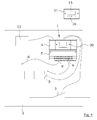
- the operator must instruct the control unit of the base unit 4 which arc detector input terminals 8, 8' are operatively linked to which circuit breakers 3, 3'.
- the control panel 7 of the arc monitor 1 is operatively connected to the control unit of the base unit 4.
- the control panel 7 comprises a display 15 and at least one key 16, e.g. a soft key.
- the control panel 7 is releasably connected to the base unit 4, as disclosed in figure 2 , and received in a seat 17.
- two screws 18 are screwed into corresponding holes 19 of the seat 17.
- a contact (not shown) of the control panel 7 is connected to a contact (not shown) of the base unit 4.
- the control panel 7 may be arranged remote from the base unit 4, e.g.
- control panel 7 comprises a primary control panel 20 releasably connected to the base unit 4 and a secondary control panel 21 arranged remote from said base unit 4, e.g. accessible from the outside of the electrical installation 2, see figure 4 .
- the secondary control panel 21 may be a computer.
- control panel 7 By means of the control panel 7 the operator may get access to information about the status of the arc monitor and may input different information to the control unit, as mentioned above.
- the arc monitor 1 has a default operation mode, during which the base unit 4 is arranged to be operatively connected to said at least one circuit breaker 3, 3', and a temporary test mode, during which the base unit 4 is arranged to be operatively disconnected from the at least one circuit breaker 3, 3' for a period of time t less than 100 milliseconds.
- the arc monitor 1 comprises an arc detector tester 22 comprising at least one artificial arc emitting means (not shown), e.g. a light emitting means such as a discharge tube, a light emitting diode, or a laser.
- the arc detector tester 22 shall be arranged in such a way that the arc detector 6 is exposable to an artificial arc emitted from said arc detector tester 22 during the temporary test mode in order to test the function of the arc detector 6.
- the control unit of the base unit 4 is arranged to examine whether the emitted artificial arc is detected by the at least one arc detector 6 and recorded in said control unit.
- the control unit of the base unit 4 is arranged to generate an indication whether said artificial arc is recorded or not, which indication is preferably displayed on the display 15 of the control panel 7.
- the test mode may be initiated according to a schedule, e.g. once a day, or manually by the operator before entering the electrical installation 2.
- the length of the period of time t is less than 100 milliseconds, preferably less than 75 milliseconds, more preferably less than 50 milliseconds, even more preferably less than 25 milliseconds, and most preferably less than 10 milliseconds, and probably about 7 milliseconds. If a true arc occur at the same time as the period of time t starts or during said period of time t, a trip signal to the circuit breaker 3, 3' will not be send before the period of time t is ended, provided that the true arc still goes on and is detected by the free end of the optical arc detector 6 after the period of time t.
- the length of the period of time t entail that a true arc has not enough time to develop in extent and discharge enough energy to cause severe damages on different types of components of the electrical installation 2, i.e. cause them to fully degrade, or to cause injuries on personnel.
- the test mode may be active when a true arc causes the arc monitor 1 to trip the circuit breaker 3, 3'. This is the case when the test mode is longer than the period of time t, and said period of time t has not started or has ended. The result of the test may thus be evaluated during the test mode but after the period of time t, during which the arc monitor 1 is operatively disconnected from the circuit breaker 3, 3'.
- the period of time is in a specific case based on the actual arcing current for a specific arc occurrence and the different types of components of the electrical installation 2.
- the different types of components are made out of materials which will degrade, i.e. catch fire, melt, disintegrate, vaporize, etc., due to discharge of enormous amounts of energy in the event of an arc occurrence.
- the different types of components are made of metal, such as steel, copper, aluminum, etc., polymers, such as cables, insulating and non-conductive materials, etc., and semiconducting materials, etc.
- the period of time may be adapted to the specific materials and the supply voltage of the electrical installation 2.
Landscapes
- Breakers (AREA)
Priority Applications (4)
| Application Number | Priority Date | Filing Date | Title |
|---|---|---|---|
| EP08166064.9A EP2175536B1 (fr) | 2008-10-08 | 2008-10-08 | Dispositif de détection d'arc |
| CN2009201589126U CN201514870U (zh) | 2008-10-08 | 2009-06-11 | 电弧监测器 |
| CN200910178441.XA CN101719659B (zh) | 2008-10-08 | 2009-09-27 | 电弧监控器 |
| US12/576,042 US9324527B2 (en) | 2008-10-08 | 2009-10-08 | Arc monitor |
Applications Claiming Priority (1)
| Application Number | Priority Date | Filing Date | Title |
|---|---|---|---|
| EP08166064.9A EP2175536B1 (fr) | 2008-10-08 | 2008-10-08 | Dispositif de détection d'arc |
Publications (2)
| Publication Number | Publication Date |
|---|---|
| EP2175536A1 true EP2175536A1 (fr) | 2010-04-14 |
| EP2175536B1 EP2175536B1 (fr) | 2017-06-07 |
Family
ID=40328243
Family Applications (1)
| Application Number | Title | Priority Date | Filing Date |
|---|---|---|---|
| EP08166064.9A Not-in-force EP2175536B1 (fr) | 2008-10-08 | 2008-10-08 | Dispositif de détection d'arc |
Country Status (3)
| Country | Link |
|---|---|
| US (1) | US9324527B2 (fr) |
| EP (1) | EP2175536B1 (fr) |
| CN (2) | CN201514870U (fr) |
Cited By (3)
| Publication number | Priority date | Publication date | Assignee | Title |
|---|---|---|---|---|
| EP2838172A3 (fr) * | 2013-08-14 | 2015-03-25 | Availon GmbH | Dispositif et procédé destinés à la détection d'arcs électriques parasites |
| EP3086426A1 (fr) * | 2015-04-23 | 2016-10-26 | Siemens Aktiengesellschaft | Disjoncteur de protection anti-feu |
| EP3487014A1 (fr) * | 2017-11-17 | 2019-05-22 | Vestel Elektronik Sanayi ve Ticaret A.S. | Agencement et procédé de protection contre les arcs électriques |
Families Citing this family (7)
| Publication number | Priority date | Publication date | Assignee | Title |
|---|---|---|---|---|
| WO2011146600A1 (fr) * | 2010-05-18 | 2011-11-24 | Smc Electrical Products, Inc | Enceinte électrique résistante à l'arc |
| US8947246B2 (en) * | 2011-09-07 | 2015-02-03 | General Electric Company | Utility meter arc detection system |
| FR3001838B1 (fr) * | 2013-02-06 | 2015-03-20 | Alstom Technology Ltd | Dispositif de traitement de signal dans une installation electrique |
| US9709433B2 (en) * | 2014-06-30 | 2017-07-18 | Rosemount Tank Radar Ab | Pulsed radar level gauging with efficient start-up |
| FR3028319B1 (fr) * | 2014-11-06 | 2017-12-22 | Airbus | Systeme et procede de detection et de passivation d'un arc electrique |
| RU2633651C1 (ru) * | 2016-06-20 | 2017-10-16 | Федеральное государственное бюджетное учреждение науки Институт сильноточной электроники Сибирского отделения Российской академии наук (ИСЭ СО РАН) | Способ обнаружения слаботочной электрической дуги в радиоэлектронной аппаратуре |
| CN110286277A (zh) * | 2019-05-31 | 2019-09-27 | 北京萨达智能技术有限公司 | 基于综合检测技术的电弧识别装置及识别方法 |
Citations (5)
| Publication number | Priority date | Publication date | Assignee | Title |
|---|---|---|---|---|
| WO1988008217A1 (fr) * | 1987-04-14 | 1988-10-20 | Strömberg Oy | Relais a arc |
| DE4440281A1 (de) * | 1994-11-11 | 1996-05-15 | Aeg Sensorsysteme Gmbh | Einrichtung zur optischen Erfassung von Störlichtbogenentladungen |
| DE102007001143A1 (de) | 2006-04-21 | 2007-10-25 | Mitsubishi Electric Corp. | Diagnosesignalprozessor |
| WO2007136836A2 (fr) * | 2006-05-19 | 2007-11-29 | Siemens Energy & Automation, Inc. | Système de détection optique d'arc électrique dans une alimentation |
| US20080192389A1 (en) * | 2007-02-12 | 2008-08-14 | Frank John Muench | Arc suppression device, system and methods for liquid insulated electrical apparatus |
Family Cites Families (9)
| Publication number | Priority date | Publication date | Assignee | Title |
|---|---|---|---|---|
| US4536126A (en) * | 1970-12-18 | 1985-08-20 | Westinghouse Electric Corp. | System and method employing a digital computer for automatically synchronizing a gas turbine or other electric power plant generator with a power system |
| US4658322A (en) * | 1982-04-29 | 1987-04-14 | The United States Of America As Represented By The Secretary Of The Navy | Arcing fault detector |
| US4940933A (en) * | 1989-04-13 | 1990-07-10 | Westinghouse Electric Corp. | Fiber optic arc monitor |
| US5825598A (en) * | 1997-02-11 | 1998-10-20 | Square D Company | Arcing fault detection system installed in a panelboard |
| US6990393B2 (en) * | 1999-09-21 | 2006-01-24 | Parker Phil A | Service panel with utility controller |
| US6678135B2 (en) * | 2001-09-12 | 2004-01-13 | General Electric Company | Module plug for an electronic trip unit |
| CN201018218Y (zh) * | 2007-02-02 | 2008-02-06 | 正泰电气股份有限公司 | 用于气体绝缘金属封闭开关的控制装置 |
| CN101141061A (zh) | 2007-06-29 | 2008-03-12 | 包头铝业股份有限公司 | 整流柜电弧光保护装置 |
| CA2736007C (fr) * | 2008-09-19 | 2014-11-18 | Schweitzer Engineering Laboratories, Inc. | Dispositif de protection avec comptage et oscillographie |
-
2008
- 2008-10-08 EP EP08166064.9A patent/EP2175536B1/fr not_active Not-in-force
-
2009
- 2009-06-11 CN CN2009201589126U patent/CN201514870U/zh not_active Expired - Lifetime
- 2009-09-27 CN CN200910178441.XA patent/CN101719659B/zh not_active Expired - Fee Related
- 2009-10-08 US US12/576,042 patent/US9324527B2/en not_active Expired - Fee Related
Patent Citations (5)
| Publication number | Priority date | Publication date | Assignee | Title |
|---|---|---|---|---|
| WO1988008217A1 (fr) * | 1987-04-14 | 1988-10-20 | Strömberg Oy | Relais a arc |
| DE4440281A1 (de) * | 1994-11-11 | 1996-05-15 | Aeg Sensorsysteme Gmbh | Einrichtung zur optischen Erfassung von Störlichtbogenentladungen |
| DE102007001143A1 (de) | 2006-04-21 | 2007-10-25 | Mitsubishi Electric Corp. | Diagnosesignalprozessor |
| WO2007136836A2 (fr) * | 2006-05-19 | 2007-11-29 | Siemens Energy & Automation, Inc. | Système de détection optique d'arc électrique dans une alimentation |
| US20080192389A1 (en) * | 2007-02-12 | 2008-08-14 | Frank John Muench | Arc suppression device, system and methods for liquid insulated electrical apparatus |
Cited By (3)
| Publication number | Priority date | Publication date | Assignee | Title |
|---|---|---|---|---|
| EP2838172A3 (fr) * | 2013-08-14 | 2015-03-25 | Availon GmbH | Dispositif et procédé destinés à la détection d'arcs électriques parasites |
| EP3086426A1 (fr) * | 2015-04-23 | 2016-10-26 | Siemens Aktiengesellschaft | Disjoncteur de protection anti-feu |
| EP3487014A1 (fr) * | 2017-11-17 | 2019-05-22 | Vestel Elektronik Sanayi ve Ticaret A.S. | Agencement et procédé de protection contre les arcs électriques |
Also Published As
| Publication number | Publication date |
|---|---|
| US9324527B2 (en) | 2016-04-26 |
| CN101719659A (zh) | 2010-06-02 |
| CN101719659B (zh) | 2015-04-29 |
| CN201514870U (zh) | 2010-06-23 |
| US20100085671A1 (en) | 2010-04-08 |
| EP2175536B1 (fr) | 2017-06-07 |
Similar Documents
| Publication | Publication Date | Title |
|---|---|---|
| US9324527B2 (en) | Arc monitor | |
| KR102057494B1 (ko) | 스마트 전기사고 예방 및 에너지 관리 시스템 | |
| EP3440760B1 (fr) | Systèmes et procédés de surveillance d'anomalie permettant de détecter des anomalies de connectivité | |
| KR101587530B1 (ko) | 다수의 안전장치 및 감시장치가 구비되고 원격 관리가 가능한 배전반 안전 통합 관리 시스템 | |
| KR101423559B1 (ko) | 수배전반용 지능형 열화감시영상시스템 | |
| US20080013596A1 (en) | Circuit breaker integral temperature monitoring for advance detection of defective power conductor connections | |
| KR20190051225A (ko) | 통합 센싱모듈을 이용한 지능형 배전반 관리시스템 | |
| KR20090126488A (ko) | 모니터링이 가능한 조립식 전원분배장치 | |
| WO2010083839A1 (fr) | Alarme d'incendie | |
| CN104777398A (zh) | 包括警报诊断显示器的绝缘监测的方法及设备 | |
| EP1971007A1 (fr) | Système et procédé de protection par défaut dans des sous-stations compacts secondaires | |
| KR20160089225A (ko) | 직류 과부하 겸용 아크 차단장치 | |
| KR101264344B1 (ko) | 배전반 내부 이상상태 감시용 디지털 컨트롤 시스템 | |
| KR102784990B1 (ko) | 양방향 멀티 펑션 전자식 누전 차단기 | |
| KR102043441B1 (ko) | IoT 기반 이동통신용 스마트 분전반 제어 장치 | |
| KR101510676B1 (ko) | 수배전반용 지능형 방전감시 영상시스템 | |
| KR101535923B1 (ko) | 전력 케이블 탄화 및 전력기기 접속 방전 상태 감시를 통한 전력 품질 진단 기능을 갖는 수배전반 | |
| KR102738164B1 (ko) | 열화감시제어 및 안전관리 기능이 적용된 인공지능형 수배전반 | |
| JP4377765B2 (ja) | 電力受変電用配電盤 | |
| KR20210001515A (ko) | 스마트 전기사고 예방 및 에너지 관리 시스템 | |
| RU2342711C2 (ru) | Способ предупреждения пожара от неисправности в электрической сети или электроустановке и устройство для его осуществления | |
| KR100882786B1 (ko) | 전력설비용 열화보호 계전시스템 | |
| US11436905B2 (en) | Socket fire alarm system | |
| KR102800932B1 (ko) | 수배전반 안전사고 예방시스템 및 그 방법 | |
| KR20220102413A (ko) | 비접촉 센싱 방식을 이용한 아크 및 열화 검출장치 |
Legal Events
| Date | Code | Title | Description |
|---|---|---|---|
| PUAI | Public reference made under article 153(3) epc to a published international application that has entered the european phase |
Free format text: ORIGINAL CODE: 0009012 |
|
| 17P | Request for examination filed |
Effective date: 20081008 |
|
| AK | Designated contracting states |
Kind code of ref document: A1 Designated state(s): AT BE BG CH CY CZ DE DK EE ES FI FR GB GR HR HU IE IS IT LI LT LU LV MC MT NL NO PL PT RO SE SI SK TR |
|
| AX | Request for extension of the european patent |
Extension state: AL BA MK RS |
|
| AKX | Designation fees paid |
Designated state(s): AT BE BG CH CY CZ DE DK EE ES FI FR GB GR HR HU IE IS IT LI LT LU LV MC MT NL NO PL PT RO SE SI SK TR |
|
| RAP1 | Party data changed (applicant data changed or rights of an application transferred) |
Owner name: ABB TECHNOLOGY LTD. |
|
| GRAP | Despatch of communication of intention to grant a patent |
Free format text: ORIGINAL CODE: EPIDOSNIGR1 |
|
| STAA | Information on the status of an ep patent application or granted ep patent |
Free format text: STATUS: GRANT OF PATENT IS INTENDED |
|
| INTG | Intention to grant announced |
Effective date: 20170208 |
|
| RAP1 | Party data changed (applicant data changed or rights of an application transferred) |
Owner name: ABB SCHWEIZ AG |
|
| GRAS | Grant fee paid |
Free format text: ORIGINAL CODE: EPIDOSNIGR3 |
|
| GRAA | (expected) grant |
Free format text: ORIGINAL CODE: 0009210 |
|
| STAA | Information on the status of an ep patent application or granted ep patent |
Free format text: STATUS: THE PATENT HAS BEEN GRANTED |
|
| AK | Designated contracting states |
Kind code of ref document: B1 Designated state(s): AT BE BG CH CY CZ DE DK EE ES FI FR GB GR HR HU IE IS IT LI LT LU LV MC MT NL NO PL PT RO SE SI SK TR |
|
| REG | Reference to a national code |
Ref country code: GB Ref legal event code: FG4D |
|
| GRAA | (expected) grant |
Free format text: ORIGINAL CODE: 0009210 |
|
| REG | Reference to a national code |
Ref country code: CH Ref legal event code: EP Ref country code: AT Ref legal event code: REF Ref document number: 899875 Country of ref document: AT Kind code of ref document: T Effective date: 20170615 |
|
| REG | Reference to a national code |
Ref country code: IE Ref legal event code: FG4D |
|
| REG | Reference to a national code |
Ref country code: DE Ref legal event code: R096 Ref document number: 602008050553 Country of ref document: DE |
|
| REG | Reference to a national code |
Ref country code: NL Ref legal event code: MP Effective date: 20170607 |
|
| REG | Reference to a national code |
Ref country code: FR Ref legal event code: PLFP Year of fee payment: 10 |
|
| REG | Reference to a national code |
Ref country code: LT Ref legal event code: MG4D |
|
| PG25 | Lapsed in a contracting state [announced via postgrant information from national office to epo] |
Ref country code: FI Free format text: LAPSE BECAUSE OF FAILURE TO SUBMIT A TRANSLATION OF THE DESCRIPTION OR TO PAY THE FEE WITHIN THE PRESCRIBED TIME-LIMIT Effective date: 20170607 Ref country code: GR Free format text: LAPSE BECAUSE OF FAILURE TO SUBMIT A TRANSLATION OF THE DESCRIPTION OR TO PAY THE FEE WITHIN THE PRESCRIBED TIME-LIMIT Effective date: 20170908 Ref country code: ES Free format text: LAPSE BECAUSE OF FAILURE TO SUBMIT A TRANSLATION OF THE DESCRIPTION OR TO PAY THE FEE WITHIN THE PRESCRIBED TIME-LIMIT Effective date: 20170607 Ref country code: LT Free format text: LAPSE BECAUSE OF FAILURE TO SUBMIT A TRANSLATION OF THE DESCRIPTION OR TO PAY THE FEE WITHIN THE PRESCRIBED TIME-LIMIT Effective date: 20170607 Ref country code: HR Free format text: LAPSE BECAUSE OF FAILURE TO SUBMIT A TRANSLATION OF THE DESCRIPTION OR TO PAY THE FEE WITHIN THE PRESCRIBED TIME-LIMIT Effective date: 20170607 Ref country code: NO Free format text: LAPSE BECAUSE OF FAILURE TO SUBMIT A TRANSLATION OF THE DESCRIPTION OR TO PAY THE FEE WITHIN THE PRESCRIBED TIME-LIMIT Effective date: 20170907 |
|
| REG | Reference to a national code |
Ref country code: AT Ref legal event code: MK05 Ref document number: 899875 Country of ref document: AT Kind code of ref document: T Effective date: 20170607 |
|
| PG25 | Lapsed in a contracting state [announced via postgrant information from national office to epo] |
Ref country code: LV Free format text: LAPSE BECAUSE OF FAILURE TO SUBMIT A TRANSLATION OF THE DESCRIPTION OR TO PAY THE FEE WITHIN THE PRESCRIBED TIME-LIMIT Effective date: 20170607 Ref country code: BG Free format text: LAPSE BECAUSE OF FAILURE TO SUBMIT A TRANSLATION OF THE DESCRIPTION OR TO PAY THE FEE WITHIN THE PRESCRIBED TIME-LIMIT Effective date: 20170907 Ref country code: NL Free format text: LAPSE BECAUSE OF FAILURE TO SUBMIT A TRANSLATION OF THE DESCRIPTION OR TO PAY THE FEE WITHIN THE PRESCRIBED TIME-LIMIT Effective date: 20170607 Ref country code: SE Free format text: LAPSE BECAUSE OF FAILURE TO SUBMIT A TRANSLATION OF THE DESCRIPTION OR TO PAY THE FEE WITHIN THE PRESCRIBED TIME-LIMIT Effective date: 20170607 |
|
| PG25 | Lapsed in a contracting state [announced via postgrant information from national office to epo] |
Ref country code: CZ Free format text: LAPSE BECAUSE OF FAILURE TO SUBMIT A TRANSLATION OF THE DESCRIPTION OR TO PAY THE FEE WITHIN THE PRESCRIBED TIME-LIMIT Effective date: 20170607 Ref country code: AT Free format text: LAPSE BECAUSE OF FAILURE TO SUBMIT A TRANSLATION OF THE DESCRIPTION OR TO PAY THE FEE WITHIN THE PRESCRIBED TIME-LIMIT Effective date: 20170607 Ref country code: RO Free format text: LAPSE BECAUSE OF FAILURE TO SUBMIT A TRANSLATION OF THE DESCRIPTION OR TO PAY THE FEE WITHIN THE PRESCRIBED TIME-LIMIT Effective date: 20170607 Ref country code: SK Free format text: LAPSE BECAUSE OF FAILURE TO SUBMIT A TRANSLATION OF THE DESCRIPTION OR TO PAY THE FEE WITHIN THE PRESCRIBED TIME-LIMIT Effective date: 20170607 Ref country code: EE Free format text: LAPSE BECAUSE OF FAILURE TO SUBMIT A TRANSLATION OF THE DESCRIPTION OR TO PAY THE FEE WITHIN THE PRESCRIBED TIME-LIMIT Effective date: 20170607 |
|
| PG25 | Lapsed in a contracting state [announced via postgrant information from national office to epo] |
Ref country code: IS Free format text: LAPSE BECAUSE OF FAILURE TO SUBMIT A TRANSLATION OF THE DESCRIPTION OR TO PAY THE FEE WITHIN THE PRESCRIBED TIME-LIMIT Effective date: 20171007 Ref country code: PL Free format text: LAPSE BECAUSE OF FAILURE TO SUBMIT A TRANSLATION OF THE DESCRIPTION OR TO PAY THE FEE WITHIN THE PRESCRIBED TIME-LIMIT Effective date: 20170607 |
|
| REG | Reference to a national code |
Ref country code: DE Ref legal event code: R097 Ref document number: 602008050553 Country of ref document: DE |
|
| PLBE | No opposition filed within time limit |
Free format text: ORIGINAL CODE: 0009261 |
|
| STAA | Information on the status of an ep patent application or granted ep patent |
Free format text: STATUS: NO OPPOSITION FILED WITHIN TIME LIMIT |
|
| PG25 | Lapsed in a contracting state [announced via postgrant information from national office to epo] |
Ref country code: DK Free format text: LAPSE BECAUSE OF FAILURE TO SUBMIT A TRANSLATION OF THE DESCRIPTION OR TO PAY THE FEE WITHIN THE PRESCRIBED TIME-LIMIT Effective date: 20170607 |
|
| 26N | No opposition filed |
Effective date: 20180308 |
|
| PG25 | Lapsed in a contracting state [announced via postgrant information from national office to epo] |
Ref country code: SI Free format text: LAPSE BECAUSE OF FAILURE TO SUBMIT A TRANSLATION OF THE DESCRIPTION OR TO PAY THE FEE WITHIN THE PRESCRIBED TIME-LIMIT Effective date: 20170607 Ref country code: MC Free format text: LAPSE BECAUSE OF FAILURE TO SUBMIT A TRANSLATION OF THE DESCRIPTION OR TO PAY THE FEE WITHIN THE PRESCRIBED TIME-LIMIT Effective date: 20170607 |
|
| REG | Reference to a national code |
Ref country code: CH Ref legal event code: PL |
|
| GBPC | Gb: european patent ceased through non-payment of renewal fee |
Effective date: 20171008 |
|
| REG | Reference to a national code |
Ref country code: IE Ref legal event code: MM4A |
|
| PG25 | Lapsed in a contracting state [announced via postgrant information from national office to epo] |
Ref country code: LI Free format text: LAPSE BECAUSE OF NON-PAYMENT OF DUE FEES Effective date: 20171031 Ref country code: LU Free format text: LAPSE BECAUSE OF NON-PAYMENT OF DUE FEES Effective date: 20171008 Ref country code: CH Free format text: LAPSE BECAUSE OF NON-PAYMENT OF DUE FEES Effective date: 20171031 Ref country code: GB Free format text: LAPSE BECAUSE OF NON-PAYMENT OF DUE FEES Effective date: 20171008 |
|
| REG | Reference to a national code |
Ref country code: BE Ref legal event code: MM Effective date: 20171031 |
|
| PG25 | Lapsed in a contracting state [announced via postgrant information from national office to epo] |
Ref country code: BE Free format text: LAPSE BECAUSE OF NON-PAYMENT OF DUE FEES Effective date: 20171031 |
|
| PG25 | Lapsed in a contracting state [announced via postgrant information from national office to epo] |
Ref country code: MT Free format text: LAPSE BECAUSE OF NON-PAYMENT OF DUE FEES Effective date: 20171008 |
|
| REG | Reference to a national code |
Ref country code: FR Ref legal event code: PLFP Year of fee payment: 11 |
|
| PG25 | Lapsed in a contracting state [announced via postgrant information from national office to epo] |
Ref country code: IE Free format text: LAPSE BECAUSE OF NON-PAYMENT OF DUE FEES Effective date: 20171008 |
|
| PGFP | Annual fee paid to national office [announced via postgrant information from national office to epo] |
Ref country code: DE Payment date: 20181019 Year of fee payment: 11 |
|
| PGFP | Annual fee paid to national office [announced via postgrant information from national office to epo] |
Ref country code: IT Payment date: 20181024 Year of fee payment: 11 Ref country code: FR Payment date: 20181023 Year of fee payment: 11 |
|
| PG25 | Lapsed in a contracting state [announced via postgrant information from national office to epo] |
Ref country code: HU Free format text: LAPSE BECAUSE OF FAILURE TO SUBMIT A TRANSLATION OF THE DESCRIPTION OR TO PAY THE FEE WITHIN THE PRESCRIBED TIME-LIMIT; INVALID AB INITIO Effective date: 20081008 |
|
| PG25 | Lapsed in a contracting state [announced via postgrant information from national office to epo] |
Ref country code: CY Free format text: LAPSE BECAUSE OF NON-PAYMENT OF DUE FEES Effective date: 20170607 |
|
| PG25 | Lapsed in a contracting state [announced via postgrant information from national office to epo] |
Ref country code: TR Free format text: LAPSE BECAUSE OF FAILURE TO SUBMIT A TRANSLATION OF THE DESCRIPTION OR TO PAY THE FEE WITHIN THE PRESCRIBED TIME-LIMIT Effective date: 20170607 |
|
| REG | Reference to a national code |
Ref country code: DE Ref legal event code: R119 Ref document number: 602008050553 Country of ref document: DE |
|
| PG25 | Lapsed in a contracting state [announced via postgrant information from national office to epo] |
Ref country code: PT Free format text: LAPSE BECAUSE OF FAILURE TO SUBMIT A TRANSLATION OF THE DESCRIPTION OR TO PAY THE FEE WITHIN THE PRESCRIBED TIME-LIMIT Effective date: 20170607 |
|
| PG25 | Lapsed in a contracting state [announced via postgrant information from national office to epo] |
Ref country code: DE Free format text: LAPSE BECAUSE OF NON-PAYMENT OF DUE FEES Effective date: 20200501 |
|
| PG25 | Lapsed in a contracting state [announced via postgrant information from national office to epo] |
Ref country code: IT Free format text: LAPSE BECAUSE OF NON-PAYMENT OF DUE FEES Effective date: 20191008 Ref country code: FR Free format text: LAPSE BECAUSE OF NON-PAYMENT OF DUE FEES Effective date: 20191031 |