EP3487014A1 - Agencement et procédé de protection contre les arcs électriques - Google Patents
Agencement et procédé de protection contre les arcs électriques Download PDFInfo
- Publication number
- EP3487014A1 EP3487014A1 EP17202433.3A EP17202433A EP3487014A1 EP 3487014 A1 EP3487014 A1 EP 3487014A1 EP 17202433 A EP17202433 A EP 17202433A EP 3487014 A1 EP3487014 A1 EP 3487014A1
- Authority
- EP
- European Patent Office
- Prior art keywords
- plug
- socket
- sensor
- pins
- electric arcing
- Prior art date
- Legal status (The legal status is an assumption and is not a legal conclusion. Google has not performed a legal analysis and makes no representation as to the accuracy of the status listed.)
- Withdrawn
Links
- 238000000034 method Methods 0.000 title claims description 13
- 238000012544 monitoring process Methods 0.000 claims abstract description 18
- 238000001514 detection method Methods 0.000 claims description 15
- 230000003213 activating effect Effects 0.000 claims description 2
- 239000002184 metal Substances 0.000 description 3
- 230000000694 effects Effects 0.000 description 1
- 238000012986 modification Methods 0.000 description 1
- 230000004048 modification Effects 0.000 description 1
- 238000013021 overheating Methods 0.000 description 1
- 230000035939 shock Effects 0.000 description 1
- 238000005406 washing Methods 0.000 description 1
Images


Classifications
-
- H—ELECTRICITY
- H01—ELECTRIC ELEMENTS
- H01R—ELECTRICALLY-CONDUCTIVE CONNECTIONS; STRUCTURAL ASSOCIATIONS OF A PLURALITY OF MUTUALLY-INSULATED ELECTRICAL CONNECTING ELEMENTS; COUPLING DEVICES; CURRENT COLLECTORS
- H01R13/00—Details of coupling devices of the kinds covered by groups H01R12/70 or H01R24/00 - H01R33/00
- H01R13/66—Structural association with built-in electrical component
- H01R13/665—Structural association with built-in electrical component with built-in electronic circuit
- H01R13/6683—Structural association with built-in electrical component with built-in electronic circuit with built-in sensor
-
- H—ELECTRICITY
- H01—ELECTRIC ELEMENTS
- H01R—ELECTRICALLY-CONDUCTIVE CONNECTIONS; STRUCTURAL ASSOCIATIONS OF A PLURALITY OF MUTUALLY-INSULATED ELECTRICAL CONNECTING ELEMENTS; COUPLING DEVICES; CURRENT COLLECTORS
- H01R13/00—Details of coupling devices of the kinds covered by groups H01R12/70 or H01R24/00 - H01R33/00
- H01R13/62—Means for facilitating engagement or disengagement of coupling parts or for holding them in engagement
- H01R13/629—Additional means for facilitating engagement or disengagement of coupling parts, e.g. aligning or guiding means, levers, gas pressure electrical locking indicators, manufacturing tolerances
- H01R13/633—Additional means for facilitating engagement or disengagement of coupling parts, e.g. aligning or guiding means, levers, gas pressure electrical locking indicators, manufacturing tolerances for disengagement only
- H01R13/635—Additional means for facilitating engagement or disengagement of coupling parts, e.g. aligning or guiding means, levers, gas pressure electrical locking indicators, manufacturing tolerances for disengagement only by mechanical pressure, e.g. spring force
-
- H—ELECTRICITY
- H01—ELECTRIC ELEMENTS
- H01R—ELECTRICALLY-CONDUCTIVE CONNECTIONS; STRUCTURAL ASSOCIATIONS OF A PLURALITY OF MUTUALLY-INSULATED ELECTRICAL CONNECTING ELEMENTS; COUPLING DEVICES; CURRENT COLLECTORS
- H01R13/00—Details of coupling devices of the kinds covered by groups H01R12/70 or H01R24/00 - H01R33/00
- H01R13/46—Bases; Cases
- H01R13/53—Bases or cases for heavy duty; Bases or cases for high voltage with means for preventing corona or arcing
-
- H—ELECTRICITY
- H01—ELECTRIC ELEMENTS
- H01R—ELECTRICALLY-CONDUCTIVE CONNECTIONS; STRUCTURAL ASSOCIATIONS OF A PLURALITY OF MUTUALLY-INSULATED ELECTRICAL CONNECTING ELEMENTS; COUPLING DEVICES; CURRENT COLLECTORS
- H01R13/00—Details of coupling devices of the kinds covered by groups H01R12/70 or H01R24/00 - H01R33/00
- H01R13/66—Structural association with built-in electrical component
- H01R13/70—Structural association with built-in electrical component with built-in switch
- H01R13/713—Structural association with built-in electrical component with built-in switch the switch being a safety switch
- H01R13/7132—Structural association with built-in electrical component with built-in switch the switch being a safety switch having ejecting mechanisms
-
- H—ELECTRICITY
- H01—ELECTRIC ELEMENTS
- H01R—ELECTRICALLY-CONDUCTIVE CONNECTIONS; STRUCTURAL ASSOCIATIONS OF A PLURALITY OF MUTUALLY-INSULATED ELECTRICAL CONNECTING ELEMENTS; COUPLING DEVICES; CURRENT COLLECTORS
- H01R2103/00—Two poles
-
- H—ELECTRICITY
- H01—ELECTRIC ELEMENTS
- H01R—ELECTRICALLY-CONDUCTIVE CONNECTIONS; STRUCTURAL ASSOCIATIONS OF A PLURALITY OF MUTUALLY-INSULATED ELECTRICAL CONNECTING ELEMENTS; COUPLING DEVICES; CURRENT COLLECTORS
- H01R24/00—Two-part coupling devices, or either of their cooperating parts, characterised by their overall structure
- H01R24/28—Coupling parts carrying pins, blades or analogous contacts and secured only to wire or cable
- H01R24/30—Coupling parts carrying pins, blades or analogous contacts and secured only to wire or cable with additional earth or shield contacts
-
- H—ELECTRICITY
- H01—ELECTRIC ELEMENTS
- H01R—ELECTRICALLY-CONDUCTIVE CONNECTIONS; STRUCTURAL ASSOCIATIONS OF A PLURALITY OF MUTUALLY-INSULATED ELECTRICAL CONNECTING ELEMENTS; COUPLING DEVICES; CURRENT COLLECTORS
- H01R24/00—Two-part coupling devices, or either of their cooperating parts, characterised by their overall structure
- H01R24/76—Two-part coupling devices, or either of their cooperating parts, characterised by their overall structure with sockets, clips or analogous contacts and secured to apparatus or structure, e.g. to a wall
- H01R24/78—Two-part coupling devices, or either of their cooperating parts, characterised by their overall structure with sockets, clips or analogous contacts and secured to apparatus or structure, e.g. to a wall with additional earth or shield contacts
Definitions
- the present disclosure relates to an electric arcing protection arrangement and method.
- Electric arcing between a plug and a socket can cause serious damage to appliances and the electrical conductivity of the sockets.
- pins of plugs and metal contacts on the sockets can burn. As they become pitted and blackened, their electrical conductivity reduces, eventually even becoming highly resistive. This can, for example, cause the damaged pins and contacts to heat up, and will eventually fail or burn up. This leaves electrical appliances and outlets in an unsafe condition, even when the damage appears minimal.
- an electric arcing protection arrangement comprising:
- the arrangement comprises a plug, wherein the plug comprises:
- the arrangement comprises a socket, wherein the socket comprises:
- the senor comprises a heat sensor arranged to monitor the temperature in a region of the connection of the plug and the socket, the electric arcing protection arrangement being such that if the temperature detected by the heat sensor is above a threshold value, the mechanism causes the pins of the plug to be withdrawn from the socket.
- the senor comprises a light sensor arranged to monitor the light level in a region of the connection of the plug and the socket, the electric arcing protection arrangement being arranged such that if the light level detected by the light sensor is above a threshold value, the mechanism causes the pins of the plug to be withdrawn from the socket.
- the senor comprises a heat sensor and a light sensor, the sensor being arranged such that:
- the mechanism comprises at least one biasing arrangement to cause the pins of the plug to be withdrawn from the socket upon detection of electric arcing between the plug and the socket by the sensor.
- the biasing arrangement comprises one or more springs arranged to push or pull the pins of the plug out of the socket.
- an electric arcing protection method comprising:
- the detection of electric arcing between the plug and the socket by a sensor comprises monitoring the temperature in a region of the connection of the plug and the socket by a heat sensor; and the mechanism is actuated if the temperature detected by the heat sensor is above a threshold value.
- the detection of electric arcing between the plug and the socket by a sensor comprises:
- the detection of electric arcing between the plug and the socket by a sensor comprises:
- causing the pins of the plug to be withdrawn from the socket comprises activating at least one biasing arrangement to cause the pins of the plug to be withdrawn from the socket upon detection of electric arcing between the plug and the socket.
- the electric arcing protection method is carried out by components in a plug.
- the electric arcing protection method is carried out by components in a socket.
- an electric arcing protection arrangement has a sensor for monitoring the presence of electrical arcing between a plug and a socket. When electric arcing is detected by the sensor, a mechanism causes the pins of the plug to be withdrawn from the socket.
- Unwanted electric arcing can occur between plug pins and metal contacts of a socket. Electric arcing can cause pins and contacts to burn, becoming pitted and less conductive over time. With further use, the socket or appliances can become faulty. Electrical arcing can cause damage to devices, inlets/outlets, and even cause electrical shocks and fires. There is required an apparatus and method for protecting plugs and sockets from damage due to electric arcing.
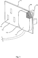
- Figure 1 shows a plug 102 connected to a socket 104.
- Pins 106 of the plug 102 are in contact with electrical contacts (not shown) within the socket holes 107.
- the plug 102 may, for example, be connected to a white goods machine, such as a refrigerator or a washing machine. Other examples of devices the plug 102 may be associated with include a television set or other electronic devices, a heater or a fan.
- the plug 102 and socket 104 shown in this figure are a British 3-pin plug 102 and socket 104.
- the plug 102 may have a different number of pins 106 and the socket 104 may have a corresponding different number of holes 107 for the pins 106 to enter.
- the plug 102 and socket 104 may follow the European or the American 2-pin standards.
- the plug 102 may be directly associated with an electronic or device or apparatus or be an adapter or a plug for an extension lead (which may lead to one or more sockets for other plugs).
- the plug 102 is shown as having a sensor 108.
- the sensor 108 is arranged to detect a change in the region of the plug 102 and socket 104 that indicates electric arcing is occurring between the pins 106 of the plug 102 and the electric contacts of the socket 104.
- the region of the plug 102 and the socket 104 may comprise for example at least one of the electrical contacts of the socket 104, the pins 106 of the plug 102, the housing 110 of the plug 102 or the cover 112 of the socket 104, depending on for example the change that is being detected and/or the detection technique used, as will be discussed further.
- the sensor 108 may comprise for example a heat sensor 108, arranged to detect whether the temperature of the region of the plug 102 and socket 104 rises above a threshold value.
- the region may be for example at least one of the pins 108, all or part of the plug housing 110, the socket holes 107 and all or part of the socket covering 112.
- the rise in temperature may be due to arcing taking place and/or because of overheating of burnt out/faulty electrical contacts or pins 106.
- the heat sensor 108 is shown on or in the housing of the plug 102. Alternatively or additionally, the heat sensor 108 may be located inside the plug 102, on the socket 104 or inside the socket 104.
- the sensor 108 may comprise a light sensor 108, arranged to detect whether the light level of the region of the plug 102 and socket 104 rises above a threshold value.
- the region of the plug 102 and socket 104 may for example be the space between the pins 106 of the plug 102 and the electrical contacts within the socket holes 107. Such a space may arise for example because of poor fitting of the pins 106 in the socket holes 107 or because for example the pins 106 have not been fully inserted into the socket holes 107.
- the light sensor 108 detects the light level of the region as being above a threshold value.
- the light sensor 108 is shown as being located on or in the plug 102.
- the light sensor 108 may alternatively be on or in the socket 104.
- the light level in the region may increase because of a spark occurring between the pins 108 and the electrical contacts within the socket holes 107.
- the sensor 108 may in one example be arranged to constantly monitor the region of the plug 102 and the socket 104, thereby enabling action to be taken to prevent electric arcing when factors such as the light level or temperature are determined as being above a threshold. In another example, the sensor 108 may be arranged to activate or trigger only when factors such as the light level or temperature of the region of the plug 102 and the socket 104 increase above a threshold value.
- the plug 102 may comprise one sensor 108, for example a heat sensor 108 or a light sensor 108, and the socket 104 may comprise another (different) sensor 108, for example a light sensor 108 or a heat sensor 108 respectively.
- both a heat sensor 108 and a light sensor 108 may be provided in the plug 102 or the socket 104.
- the heat sensor and the light sensor may be provided as separate items or as a unitary sensor.
- a mechanism (not shown) is activated to cause the pins 106 to be withdrawn from the electrical contacts of the socket holes 107.
- the mechanism comprises a biasing arrangement for withdrawing the pins 106 from the socket 104.
- the biasing arrangement may for example be or include a spring system.
- the plug 102 comprises a mechanism for pulling the pins 106 into the plug 102 when electric arcing is detected between the plug 102 at the socket 104.
- the plug 102 has a sensor 108 for detecting a change in the region of the plug 102 and the socket 104.
- the plug 102 also has a mechanism for withdrawing the pins 106 from the socket 104.
- the mechanism may be arranged such that in a default position the pins 106 protrude from the plug 102.
- the plug 102 is arranged such that when the sensor(s) 108 indicates that arcing is taking place, the mechanism is activated to extract the pins 106 from the socket 104 and into the body of the plug 102.
- the plug 102 having withdrawn the pins 106 away from the socket 104, is able to fall away from the socket 104, thereby reducing the chance of damage to the plug 102 and/or socket 104 by electric arcing.
- Figures 3A and 3B show another example of the plug 102 and socket 104 in use, wherein the mechanism to cause the pins 106 to be withdrawn is contained in the socket 104.
- the mechanism is arranged such that when electric arcing is detected the pins 106 of the plug 102 are pushed out of the socket 104.
- the sensor 108 detects the temperature and light level of the region between the plug 102 and the socket 104 as being above the threshold heat and light values respectively
- the mechanism pushes the pins 106 of the plug 102 out of the socket 104.
- the plug 102 is free to fall away from the socket 104, thereby reducing or eliminating damage to the plug 102 and/or socket 104 by electric arcing.
Landscapes
- Engineering & Computer Science (AREA)
- Microelectronics & Electronic Packaging (AREA)
- Details Of Connecting Devices For Male And Female Coupling (AREA)
- Testing Of Short-Circuits, Discontinuities, Leakage, Or Incorrect Line Connections (AREA)
Priority Applications (2)
| Application Number | Priority Date | Filing Date | Title |
|---|---|---|---|
| EP17202433.3A EP3487014A1 (fr) | 2017-11-17 | 2017-11-17 | Agencement et procédé de protection contre les arcs électriques |
| TR2017/19152A TR201719152A2 (tr) | 2017-11-17 | 2017-11-29 | Elektrik Arkından Koruma Düzenlemesi Ve Yöntemi |
Applications Claiming Priority (1)
| Application Number | Priority Date | Filing Date | Title |
|---|---|---|---|
| EP17202433.3A EP3487014A1 (fr) | 2017-11-17 | 2017-11-17 | Agencement et procédé de protection contre les arcs électriques |
Publications (1)
| Publication Number | Publication Date |
|---|---|
| EP3487014A1 true EP3487014A1 (fr) | 2019-05-22 |
Family
ID=60409192
Family Applications (1)
| Application Number | Title | Priority Date | Filing Date |
|---|---|---|---|
| EP17202433.3A Withdrawn EP3487014A1 (fr) | 2017-11-17 | 2017-11-17 | Agencement et procédé de protection contre les arcs électriques |
Country Status (2)
| Country | Link |
|---|---|
| EP (1) | EP3487014A1 (fr) |
| TR (1) | TR201719152A2 (fr) |
Cited By (3)
| Publication number | Priority date | Publication date | Assignee | Title |
|---|---|---|---|---|
| CN113820043A (zh) * | 2021-09-29 | 2021-12-21 | 湖北工业大学 | 电气工程用检测装置及方法 |
| EP4016757A1 (fr) * | 2020-12-17 | 2022-06-22 | Vestel Elektronik Sanayi ve Ticaret A.S. | Connecteur électrique et procédé |
| US12316090B2 (en) | 2023-03-08 | 2025-05-27 | Pratt & Whitney Canada Corp. | Temperature sensor for arc detection |
Citations (11)
| Publication number | Priority date | Publication date | Assignee | Title |
|---|---|---|---|---|
| DE3141374A1 (de) * | 1981-10-02 | 1983-04-28 | Licentia Patent-Verwaltungs-Gmbh, 6000 Frankfurt | Anordnung zur ueberwachung von elektrischen einrichtungen auf die ausbildung eines oder mehrerer lichtboegen |
| WO2002087028A1 (fr) * | 2001-04-24 | 2002-10-31 | Kontavill Rt. | Receptacle de connecteur dote de moyen d'ejection |
| US20080146058A1 (en) * | 2006-12-18 | 2008-06-19 | Ernest A. Kussmaul | Automatic power line disconnect apparatus |
| EP2175536A1 (fr) * | 2008-10-08 | 2010-04-14 | Abb Ab | Dispositif de détection d'arc |
| TW201228149A (en) * | 2010-12-20 | 2012-07-01 | Hon Hai Prec Ind Co Ltd | Outlet for automatically ejecting a plug |
| US20130057408A1 (en) * | 2011-09-07 | 2013-03-07 | General Electric Company | Utility meter arc detection system |
| KR101379422B1 (ko) * | 2013-02-28 | 2014-03-28 | 주식회사 에이 씨 에스 | 플러그의 분리가 용이한 콘센트 |
| US20140342590A1 (en) * | 2013-05-14 | 2014-11-20 | Kuwait University | Electrical outlet safety device |
| CN205081271U (zh) * | 2015-11-17 | 2016-03-09 | 赵振华 | 插座 |
| US20170077693A1 (en) * | 2015-09-10 | 2017-03-16 | Jonathan Lermann | System and apparatus for sensing temperature to prevent electrical fires |
| CN106654720A (zh) * | 2016-12-22 | 2017-05-10 | 六安力达生产力促进中心有限公司 | 插座的弹射脱离装置 |
-
2017
- 2017-11-17 EP EP17202433.3A patent/EP3487014A1/fr not_active Withdrawn
- 2017-11-29 TR TR2017/19152A patent/TR201719152A2/tr unknown
Patent Citations (11)
| Publication number | Priority date | Publication date | Assignee | Title |
|---|---|---|---|---|
| DE3141374A1 (de) * | 1981-10-02 | 1983-04-28 | Licentia Patent-Verwaltungs-Gmbh, 6000 Frankfurt | Anordnung zur ueberwachung von elektrischen einrichtungen auf die ausbildung eines oder mehrerer lichtboegen |
| WO2002087028A1 (fr) * | 2001-04-24 | 2002-10-31 | Kontavill Rt. | Receptacle de connecteur dote de moyen d'ejection |
| US20080146058A1 (en) * | 2006-12-18 | 2008-06-19 | Ernest A. Kussmaul | Automatic power line disconnect apparatus |
| EP2175536A1 (fr) * | 2008-10-08 | 2010-04-14 | Abb Ab | Dispositif de détection d'arc |
| TW201228149A (en) * | 2010-12-20 | 2012-07-01 | Hon Hai Prec Ind Co Ltd | Outlet for automatically ejecting a plug |
| US20130057408A1 (en) * | 2011-09-07 | 2013-03-07 | General Electric Company | Utility meter arc detection system |
| KR101379422B1 (ko) * | 2013-02-28 | 2014-03-28 | 주식회사 에이 씨 에스 | 플러그의 분리가 용이한 콘센트 |
| US20140342590A1 (en) * | 2013-05-14 | 2014-11-20 | Kuwait University | Electrical outlet safety device |
| US20170077693A1 (en) * | 2015-09-10 | 2017-03-16 | Jonathan Lermann | System and apparatus for sensing temperature to prevent electrical fires |
| CN205081271U (zh) * | 2015-11-17 | 2016-03-09 | 赵振华 | 插座 |
| CN106654720A (zh) * | 2016-12-22 | 2017-05-10 | 六安力达生产力促进中心有限公司 | 插座的弹射脱离装置 |
Cited By (4)
| Publication number | Priority date | Publication date | Assignee | Title |
|---|---|---|---|---|
| EP4016757A1 (fr) * | 2020-12-17 | 2022-06-22 | Vestel Elektronik Sanayi ve Ticaret A.S. | Connecteur électrique et procédé |
| CN113820043A (zh) * | 2021-09-29 | 2021-12-21 | 湖北工业大学 | 电气工程用检测装置及方法 |
| CN113820043B (zh) * | 2021-09-29 | 2023-08-29 | 义乌建投建设发展有限公司 | 电气工程用检测装置及方法 |
| US12316090B2 (en) | 2023-03-08 | 2025-05-27 | Pratt & Whitney Canada Corp. | Temperature sensor for arc detection |
Also Published As
| Publication number | Publication date |
|---|---|
| TR201719152A2 (tr) | 2019-06-21 |
Similar Documents
| Publication | Publication Date | Title |
|---|---|---|
| US7575467B2 (en) | Electrically safe receptacle | |
| US6132257A (en) | Electrical socket device with overheating and overcurrent protection | |
| EP3487014A1 (fr) | Agencement et procédé de protection contre les arcs électriques | |
| US2988617A (en) | Three wire safety fuse adapter, grounding type | |
| CN103682854A (zh) | 电源线 | |
| WO2017044947A1 (fr) | Système et appareil de détection de la température pour empêcher des feux électriques | |
| US8159803B2 (en) | Heat actuated interrupter receptacle | |
| JP6054600B2 (ja) | コネクタ | |
| CN206211197U (zh) | 一种防开路插拔电连接器 | |
| CN106936030B (zh) | 用于电子设备的接地端子 | |
| US20070139842A1 (en) | Safety lug suitable for the connection to a current outlet | |
| US12237624B2 (en) | Safety device for socket | |
| EP3358594A1 (fr) | Disjoncteur à un seul étage | |
| CN109038030B (zh) | 单芯金属连接器 | |
| CN105337077A (zh) | 安全插座 | |
| US20030085108A1 (en) | Electrical safety outlet which can prevent electric shocks from accidental contacts | |
| CN205509163U (zh) | 一种温度保护插头及温度保护电器 | |
| CN104241037B (zh) | 漏电断路器 | |
| US20110275245A1 (en) | Electrical plug-in connector for applications critical to plug safety | |
| CN106783416A (zh) | 一种安全型漏电断路器及其使用方法 | |
| JP2000348825A (ja) | コンセント | |
| CN106252951B (zh) | 一种防触电插座 | |
| JP6392381B2 (ja) | 自動車用シガーライター及び電源コンセントのためのコンパクト保護装置 | |
| US8253432B2 (en) | Fork assembly for protection circuit of test system | |
| CN105048215A (zh) | 自动短路功能的电连接器 |
Legal Events
| Date | Code | Title | Description |
|---|---|---|---|
| PUAI | Public reference made under article 153(3) epc to a published international application that has entered the european phase |
Free format text: ORIGINAL CODE: 0009012 |
|
| STAA | Information on the status of an ep patent application or granted ep patent |
Free format text: STATUS: THE APPLICATION HAS BEEN PUBLISHED |
|
| AK | Designated contracting states |
Kind code of ref document: A1 Designated state(s): AL AT BE BG CH CY CZ DE DK EE ES FI FR GB GR HR HU IE IS IT LI LT LU LV MC MK MT NL NO PL PT RO RS SE SI SK SM TR |
|
| AX | Request for extension of the european patent |
Extension state: BA ME |
|
| STAA | Information on the status of an ep patent application or granted ep patent |
Free format text: STATUS: REQUEST FOR EXAMINATION WAS MADE |
|
| 17P | Request for examination filed |
Effective date: 20191120 |
|
| RBV | Designated contracting states (corrected) |
Designated state(s): AL AT BE BG CH CY CZ DE DK EE ES FI FR GB GR HR HU IE IS IT LI LT LU LV MC MK MT NL NO PL PT RO RS SE SI SK SM TR |
|
| STAA | Information on the status of an ep patent application or granted ep patent |
Free format text: STATUS: EXAMINATION IS IN PROGRESS |
|
| 17Q | First examination report despatched |
Effective date: 20200429 |
|
| STAA | Information on the status of an ep patent application or granted ep patent |
Free format text: STATUS: THE APPLICATION HAS BEEN WITHDRAWN |
|
| 18W | Application withdrawn |
Effective date: 20200825 |