EP2176054B1 - Dispositif et procédé de soufflage destiné à dilater des récipients - Google Patents
Dispositif et procédé de soufflage destiné à dilater des récipients Download PDFInfo
- Publication number
- EP2176054B1 EP2176054B1 EP08774768.9A EP08774768A EP2176054B1 EP 2176054 B1 EP2176054 B1 EP 2176054B1 EP 08774768 A EP08774768 A EP 08774768A EP 2176054 B1 EP2176054 B1 EP 2176054B1
- Authority
- EP
- European Patent Office
- Prior art keywords
- blowing
- nozzle
- container
- piston
- longitudinal direction
- Prior art date
- Legal status (The legal status is an assumption and is not a legal conclusion. Google has not performed a legal analysis and makes no representation as to the accuracy of the status listed.)
- Not-in-force
Links
Images


Classifications
-
- B—PERFORMING OPERATIONS; TRANSPORTING
- B29—WORKING OF PLASTICS; WORKING OF SUBSTANCES IN A PLASTIC STATE IN GENERAL
- B29C—SHAPING OR JOINING OF PLASTICS; SHAPING OF MATERIAL IN A PLASTIC STATE, NOT OTHERWISE PROVIDED FOR; AFTER-TREATMENT OF THE SHAPED PRODUCTS, e.g. REPAIRING
- B29C49/00—Blow-moulding, i.e. blowing a preform or parison to a desired shape within a mould; Apparatus therefor
- B29C49/42—Component parts, details or accessories; Auxiliary operations
- B29C49/58—Blowing means
-
- B—PERFORMING OPERATIONS; TRANSPORTING
- B29—WORKING OF PLASTICS; WORKING OF SUBSTANCES IN A PLASTIC STATE IN GENERAL
- B29C—SHAPING OR JOINING OF PLASTICS; SHAPING OF MATERIAL IN A PLASTIC STATE, NOT OTHERWISE PROVIDED FOR; AFTER-TREATMENT OF THE SHAPED PRODUCTS, e.g. REPAIRING
- B29C49/00—Blow-moulding, i.e. blowing a preform or parison to a desired shape within a mould; Apparatus therefor
- B29C49/42—Component parts, details or accessories; Auxiliary operations
- B29C2049/4294—Sealing means
-
- B—PERFORMING OPERATIONS; TRANSPORTING
- B29—WORKING OF PLASTICS; WORKING OF SUBSTANCES IN A PLASTIC STATE IN GENERAL
- B29C—SHAPING OR JOINING OF PLASTICS; SHAPING OF MATERIAL IN A PLASTIC STATE, NOT OTHERWISE PROVIDED FOR; AFTER-TREATMENT OF THE SHAPED PRODUCTS, e.g. REPAIRING
- B29C49/00—Blow-moulding, i.e. blowing a preform or parison to a desired shape within a mould; Apparatus therefor
- B29C49/42—Component parts, details or accessories; Auxiliary operations
- B29C49/58—Blowing means
- B29C2049/5806—Means for fixing the blowing means with the mould
- B29C2049/5817—Pneumatic
-
- B—PERFORMING OPERATIONS; TRANSPORTING
- B29—WORKING OF PLASTICS; WORKING OF SUBSTANCES IN A PLASTIC STATE IN GENERAL
- B29C—SHAPING OR JOINING OF PLASTICS; SHAPING OF MATERIAL IN A PLASTIC STATE, NOT OTHERWISE PROVIDED FOR; AFTER-TREATMENT OF THE SHAPED PRODUCTS, e.g. REPAIRING
- B29C49/00—Blow-moulding, i.e. blowing a preform or parison to a desired shape within a mould; Apparatus therefor
- B29C49/42—Component parts, details or accessories; Auxiliary operations
- B29C49/58—Blowing means
- B29C2049/5862—Drive means therefore
- B29C2049/5868—Hydraulic
-
- B—PERFORMING OPERATIONS; TRANSPORTING
- B29—WORKING OF PLASTICS; WORKING OF SUBSTANCES IN A PLASTIC STATE IN GENERAL
- B29C—SHAPING OR JOINING OF PLASTICS; SHAPING OF MATERIAL IN A PLASTIC STATE, NOT OTHERWISE PROVIDED FOR; AFTER-TREATMENT OF THE SHAPED PRODUCTS, e.g. REPAIRING
- B29C49/00—Blow-moulding, i.e. blowing a preform or parison to a desired shape within a mould; Apparatus therefor
- B29C49/42—Component parts, details or accessories; Auxiliary operations
- B29C49/58—Blowing means
- B29C2049/5893—Mounting, exchanging or centering blowing means
-
- B—PERFORMING OPERATIONS; TRANSPORTING
- B29—WORKING OF PLASTICS; WORKING OF SUBSTANCES IN A PLASTIC STATE IN GENERAL
- B29C—SHAPING OR JOINING OF PLASTICS; SHAPING OF MATERIAL IN A PLASTIC STATE, NOT OTHERWISE PROVIDED FOR; AFTER-TREATMENT OF THE SHAPED PRODUCTS, e.g. REPAIRING
- B29C49/00—Blow-moulding, i.e. blowing a preform or parison to a desired shape within a mould; Apparatus therefor
- B29C49/42—Component parts, details or accessories; Auxiliary operations
- B29C49/58—Blowing means
- B29C2049/5893—Mounting, exchanging or centering blowing means
- B29C2049/5898—Regulation of the blowing means clamp force
-
- B—PERFORMING OPERATIONS; TRANSPORTING
- B29—WORKING OF PLASTICS; WORKING OF SUBSTANCES IN A PLASTIC STATE IN GENERAL
- B29C—SHAPING OR JOINING OF PLASTICS; SHAPING OF MATERIAL IN A PLASTIC STATE, NOT OTHERWISE PROVIDED FOR; AFTER-TREATMENT OF THE SHAPED PRODUCTS, e.g. REPAIRING
- B29C2949/00—Indexing scheme relating to blow-moulding
- B29C2949/07—Preforms or parisons characterised by their configuration
- B29C2949/0715—Preforms or parisons characterised by their configuration the preform having one end closed
-
- B—PERFORMING OPERATIONS; TRANSPORTING
- B29—WORKING OF PLASTICS; WORKING OF SUBSTANCES IN A PLASTIC STATE IN GENERAL
- B29C—SHAPING OR JOINING OF PLASTICS; SHAPING OF MATERIAL IN A PLASTIC STATE, NOT OTHERWISE PROVIDED FOR; AFTER-TREATMENT OF THE SHAPED PRODUCTS, e.g. REPAIRING
- B29C49/00—Blow-moulding, i.e. blowing a preform or parison to a desired shape within a mould; Apparatus therefor
- B29C49/02—Combined blow-moulding and manufacture of the preform or the parison
- B29C49/06—Injection blow-moulding
-
- B—PERFORMING OPERATIONS; TRANSPORTING
- B29—WORKING OF PLASTICS; WORKING OF SUBSTANCES IN A PLASTIC STATE IN GENERAL
- B29C—SHAPING OR JOINING OF PLASTICS; SHAPING OF MATERIAL IN A PLASTIC STATE, NOT OTHERWISE PROVIDED FOR; AFTER-TREATMENT OF THE SHAPED PRODUCTS, e.g. REPAIRING
- B29C49/00—Blow-moulding, i.e. blowing a preform or parison to a desired shape within a mould; Apparatus therefor
- B29C49/42—Component parts, details or accessories; Auxiliary operations
- B29C49/4205—Handling means, e.g. transfer, loading or discharging means
- B29C49/42073—Grippers
- B29C49/42087—Grippers holding outside the neck
Definitions
- the invention relates to a device for treating containers and in particular a blowing device for expanding containers.
- the invention is also directed to a method for expanding containers.
- an orifice will be understood to mean an area of the preform which has a collar and an area extending over this collar in the direction of the pouring opening.
- the mouth has a thread.
- a collar is understood to mean a radially projecting, at least partially circumferential accumulation of material, which is preferably designed as a ring.
- the collar can in this case as a support ring, but also as a retaining ring, be formed.
- the invention is not limited to the use of the above orifices.
- US-A-4552527 discloses a blowing device according to the preamble of claim 1 and a method for expanding containers according to the preamble of claim 13.
- the blow piston is lowered onto the vessel and usually pressed against this.
- the contact pressure is relatively difficult to control. Excessive pressure on the preform mouth may result in deformation and too little pressure to ensure proper sealing between the blower and the container.
- the present invention is therefore based on the object to improve a blowing process for plastic containers and in particular to improve the seal between the blowing device and the container without simultaneously risking deformation of the preform.
- the blowing device for expanding containers with a gaseous medium has a blowing piston and a blowing nozzle, wherein the container is expanded with the gaseous medium through the blowing nozzle.
- the blowing piston is movable in a longitudinal direction of the blowing nozzle, and the blowing nozzle is also movable with respect to the blowing piston in the longitudinal direction, and further comprising guide means for guiding the movement of the blowing nozzle in the longitudinal direction with respect to the blowing piston.
- this longitudinal direction is usually also the longitudinal direction of the container to be expanded and further a degree of freedom of movement of the blowing nozzle relative to the blowing piston in the longitudinal direction.
- this further degree of freedom of movement in the longitudinal direction is a finer regulation of the contact pressure of the blowing device relative to the container possible.
- the blowing nozzle is designed such that it is urged upon exposure of the container with the gaseous medium through the gaseous medium in the direction of the container. This means that the air flow, which causes an expansion of the container, at the same time also urges the blowing nozzle and possibly also the guide device in the direction of the container and thus causes a sealing effect between the container and the guide device.
- the blowing nozzle is arranged radially inside the guide device and is guided in this way by the guide device.
- the blowing device has a biasing device, which urges the blowing nozzle relative to the blowing piston and possibly also with respect to the guide device in the longitudinal direction and in the direction of the container.
- the blowing nozzle is guided movably parallel to the pis- ton piston axis and is prestressed by means of a spring, preferably a spiral spring. The leadership is there also mounted on the blow piston. By the spring is thus causes a certain bias of the nozzle relative to the container.
- the blowing nozzle has a first section (nozzle section) with a first inner cross section and a second section (nozzle piston) with a second inner cross section.
- the first inner cross section deviates from the second inner cross section.
- a lower cross-section of the tuyere provided and an upper this opposite larger cross-section.
- the nozzle preferably has a nozzle diameter adapted to the associated preform diameter and a resulting surface matched to the desired contact pressure between nozzle and preform.
- the gaseous medium flowing through the nozzle for expanding the container in this way causes a pressure on the resulting surface, which results from the difference between the two inner cross sections and thus causes a pressing of the nozzle or on the guide device relative to the container.
- the nozzle itself has a sealant which seals against, for example, the top of the mouth or other areas of the mouth.
- the sealant can be both an elastomer, as well as the nozzle itself, so then a seal between the metal (blowing nozzle) and plastic (container).
- the inner cross-section of the tuyere nozzle tapers in the longitudinal direction from top to bottom. This taper can preferably steadily respectively. In this case, it is achieved by the tapering internal cross section that the medium passing through the blowing nozzle forces the blowing nozzle in the direction of the container.
- the guide device has an inner wall which surrounds the mouth of the container during the blowing process in the longitudinal direction of the container at least in sections, but in full circumference. In this way, an improved centering of the blowing device relative to the container to be expanded can be achieved.
- a guiding device is understood to mean any device which leads a movement of one element with respect to another element.
- the guide device is preferably arranged immovably on the blow piston and in the longitudinal direction with respect to a blow piston.
- the guide device is also arranged detachably on the blow piston.
- the guide means can be replaced together with the tuyere to quickly achieve a conversion to other muzzle properties.
- the guide device is fixedly arranged on the blowing nozzle and movable relative to the blowing piston.
- the concept according to the invention makes a blow piston change superfluous in the event of a change of fittings, it is sufficient merely to exchange the blowing nozzle with its guide device.
- the blowing device has a sealing device, which during the blowing operation is in contact with a portion of the wall of the container and seals a space between the tuyere and a wall of the container.
- This sealing device is, as mentioned above, preferably arranged on the tuyere and causes the container can be expanded without the gaseous medium, such as blowing air, can escape to the outside.
- the region of the wall is an upper mouth edge of the container and thus the blowing device is a top-sealing blowing device.
- This sealing device is preferably made of an elastomer or has such.
- the sealing direction can also be metallic, so that then a seal between a plastic (container) and a metal (blowing nozzle) takes place.
- the region of the orifice is a region of the outer circumference of the mouth of the container and preferably the support ring of the container and thus the blowing device is an externally sealing blowing device.
- the blow piston is moved to a lower end position and the nozzle is pressed onto the preform via the pretensioning device. Subsequently, the preform is expanded or the bottle is blown.
- the biasing means which seals the nozzle relative to the support ring or against a region of the mouth.
- a sealing ring is provided between the guide device and the blowing nozzle.
- the blowing nozzle is secured to the guide device by means of a screw body which surrounds the blowing nozzle in the circumferential direction.
- the guide device preferably has a thread. By loosening the screw body, the blowing nozzle itself can be released from the guide device in this way.
- the guide device is detachable from the blow piston, for example by loosening one or more screws.
- the present invention is further directed to an arrangement for expanding containers with a blowing device of the type described above.
- the present invention is used in the manufacture of plastic bottles, and preferably PET.
- the invention relates in particular to a stretch blow molding machine and more particularly to a rotary stretch blow molding machine.
- a stretch blow molding machine there are a plurality of blowing devices according to the invention, each having at least one blow mold, a device for producing bottles, and preferably at least three valves for switching or controlling the blown air. These valves control the supply of the blowing air for expanding the containers.
- air which serves to expand the containers at the same time also serves to ensure that an increased contact pressure of the tuyere is reached to the container.
- the present invention is further directed to a method for filling and expanding containers with a gaseous medium.
- a blow piston is lowered with a blow nozzle on this blow piston in the longitudinal direction of the container movably arranged in the longitudinal direction of the container up to a predetermined end position of the blow piston relative to the container.
- the container is filled by the blowing nozzle with the gaseous medium.
- the gaseous medium flowing through the blowing nozzle causes, during the filling or expansion process, that the blowing nozzle is urged in the direction of the container in the longitudinal direction of the container or that the blowing nozzle exerts pressure on the container in the longitudinal direction.
- blowing nozzle causes the blowing piston to be moved towards the mouth.
- the additional pressure of the tuyere is effected on the container by a biasing means such as a coil spring instead of the air flow. It is also possible to make the coil spring or its arrangement so that the spring force can be changed to the blowing nozzle by the user. Particularly preferably, however, the pressure on the container is effected both by the coil spring and by the air flowing through during the expansion process.
- the blowing nozzle is biased by a biasing or spring device relative to the container.
- the blowing nozzle is guided in the longitudinal direction by means of a guide device movable relative to the blowing piston.
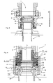
- Fig. 1 shows a blowing device 1 according to the invention in a first embodiment.
- This blowing device 1 has a blowing piston 2.
- the blow piston 2 is driven by a (not shown) Leitkurve in a certain (end) position to apply in this (end) position a container 10, here a preform, with compressed air to expand it thereby.
- the container 10 is arranged by means of a centering plate 30 in a (not shown) blow mold.
- the Reference numeral 32 shows a projection of the centering plate 30, which is supported against a support ring 10b of the container.
- the reference numeral 10a refers in its entirety to an orifice of the container 10. At this mouth 10a, a thread 10c and another ring 10d are provided.
- a guide device 4 is detachably mounted on the blow piston 2, a guide device 4 is detachably mounted.
- a blowing nozzle 6 is arranged to be movable relative to this guide device 4 in a longitudinal direction L. In this case, the blowing nozzle 6 is moved by a spring on the container 10.
- the reference numeral 24 refers to a screw body, with which the blowing nozzle 6 is screwed into the guide device 4. More precisely, this screw body 24 has a screw thread 24a, which cooperates with a corresponding internal thread of the guide device 4.
- the tuyere 6 has an inner cross section A nozzle inside .
- the tuyere 6 has a nozzle piston 16, which is movable relative to the guide device 4 in the longitudinal direction L.
- This nozzle piston 16 has an inner cross section A piston nozzle .
- the reference numeral A preform, inside refers to the inner cross section of the preform or container 10, in particular its mouth 10a.
- the tuyere 6 has a nozzle diameter adapted to the associated preform diameter and a resulting surface which is matched to the desired contact pressure between the tuyere 6 and the container 10.
- This tuning is done by a suitable choice of the guide diameter or guide radius R guide , since the resulting area A Res results as follows:
- a Res R F ⁇ u ⁇ ⁇ currency 2 - R D ⁇ u ⁇ ⁇ se 2 ⁇ ⁇
- the radius of the tuyere R nozzle (or of the nozzle section 14) is already determined by the type of preform.
- Fig. 2 shows a blowing device Fig. 1 in a first working position, ie before the blowing device 1 is placed on the mouth 10a of the container 10 (or preferably the outer wall of this mouth 10a).
- the guide device 4 is firmly but detachably mounted via a screw 26, 27.
- the compressed air passes through the blowing piston 2 in the direction L to the tuyere 6.
- This tuyere 6 has a nozzle portion 14 and the above-mentioned nozzle piston 16.
- This nozzle piston 16 and the nozzle portion 14 are formed integrally with each other and connected via a radially extending ring 15.
- the reference numeral 28 refers to a sealing device with which the blowing piston 6 is sealed relative to the guide device 4.
- the blowing piston 6 has a sealing device 22 on its underside, which can be pressed against a mouth edge 10e of the container 10.
- the reference numeral 13 refers to a guide ring for guiding the tuyere 6 with respect to the guide device 4.
- the threaded body 24 and the limiting nut 24 simultaneously limits the movement of the tuyere 6 relative to the guide device 4 in the longitudinal direction L.
- Fig. 3 shows a position of the blowing device 1, in which it is in contact with the mouth 10 a of the container 10. More specifically, the above-mentioned mouth edge 10e now bears against the sealing means 22 of the tuyere 6, so that the space between the tuyere 6, more particularly its nozzle portion 14 and the container 10, is sealed.
- Fig. 5 shows a further embodiment of a blowing device according to the invention 1.
- a sealing of the container 10 from the outside more precisely on the support ring 10b of the container 10.
- the guide device 4 is fixed in the longitudinal direction L at the tuyere 6 is arranged. More specifically, the guide means 4 is locked in the longitudinal direction by a lower nose 46 and a first locking ring 44.
- the guide means 4 in the longitudinal direction L is movable relative to the blow piston 2 and a fixed to this blow piston 2 intermediate piece 37.
- a second locking ring 42 is provided in addition to the aforementioned first locking ring 44.
- the reference numeral 36 refers to a sealing device formed between the guide 4 and the intermediate piece 37, more specifically an inner wall 18 of the guide device 4 and the intermediate piece 37, is provided.
- the reference numeral 41 refers to a guide ring.
- the intermediate piece 37 is here arranged with the aid of a quick release on the blow piston 2, wherein the reference numeral 38 refers to balls of this quick release.
- the reference numeral 38 refers to balls of this quick release.
- other possibilities are conceivable for releasably arranging the intermediate piece 37 on the blowing piston, such as screw thread.
- the reference numeral 12 refers here again to a coil spring, which is provided between the blowing nozzle 6 and the blowing piston 2, more precisely, the fixedly arranged on the blowing piston 2 intermediate piece 37.
- the force acting on the blowing nozzle depends only on the cross-section A piston nozzle of the nozzle piston 16 and the active surface A effective area .
Landscapes
- Engineering & Computer Science (AREA)
- Manufacturing & Machinery (AREA)
- Mechanical Engineering (AREA)
- Blow-Moulding Or Thermoforming Of Plastics Or The Like (AREA)
Claims (15)
- Dispositif de soufflage (1) pour l'expansion de récipients (10) par un fluide gazeux, avec un piston de soufflage (2) et avec une buse de soufflage (6) au moyen de laquelle le récipient (10) est dilaté par le fluide gazeux, le piston de soufflage (2) étant mobile dans une direction longitudinale (L) de la buse de soufflage (6), la buse de soufflage (6) étant mobile dans la direction longitudinale (L) par rapport au piston de soufflage (2) et un dispositif de guidage (4) étant prévu, lequel guide le déplacement de la buse de soufflage (6) dans la direction longitudinale (L) par rapport au piston de soufflage (2), et la buse de soufflage (6) étant configurée de manière à être repoussée dans la direction du récipient (10) par une application du fluide gazeux sur le récipient (10), caractérisé en ce que la buse de soufflage (6) présente un segment de buse (14) avec une première section transversale intérieure (Abuse, intérieur) et un piston de buse (16) formé d'un seul tenant avec le segment de buse (14) et qui lui est raccordé par une bague (15) à extension radiale, avec une deuxième section transversale intérieure (Apiston-buse), ladite deuxième section transversale intérieure (Apiston-buse ) étant différente de la première section transversale intérieure (Abuse, intérieur).
- Dispositif de soufflage (1) selon la revendication 1, caractérisé en ce que la buse de soufflage (6) est disposée radialement à l'intérieur du dispositif de guidage (4).
- Dispositif de soufflage (1) selon la revendication 1, caractérisé en ce que ledit dispositif de soufflage (1) comporte un dispositif de pré-contrainte (12) qui repousse la buse de soufflage (6) vers le récipient (10), dans la direction longitudinale (L) par rapport au piston de soufflage (2).
- Dispositif de soufflage (1) selon au moins une des revendications précédentes, caractérisé en ce que le dispositif de guidage (4) comporte une paroi intérieure (18) qui entoure une embouchure (10a) du récipient (10) pendant le processus de soufflage.
- Dispositif de soufflage selon la revendication 1, caractérisé en ce que le dispositif de guidage (4) est disposé sur le piston de soufflage (2) et immobile dans la direction longitudinale (L) par rapport au piston de soufflage (2).
- Dispositif de soufflage (1) selon la revendication 1, caractérisé en ce que le dispositif de guidage (4) est disposé de manière amovible sur le piston de soufflage (2).
- Dispositif de soufflage (1) selon au moins une des revendications précédentes, caractérisé en ce que le dispositif de soufflage (1) comporte un dispositif d'étanchéité (22) qui est en contact avec une zone de l'embouchure (10a) du récipient (10) pendant le processus de soufflage et rend étanche un espace entre la buse de soufflage (6) et la zone de l'embouchure (10a) du récipient (10).
- Dispositif de soufflage (1) selon la revendication 7, caractérisé en ce que la zone de l'embouchure (10a) est un bord d'embouchure supérieur (10e) du récipient (10).
- Dispositif de soufflage (1) selon la revendication 7, caractérisé en ce que la zone de l'embouchure (10a) est une zone du contour extérieur de l'embouchure (10a) du récipient (10).
- Dispositif de soufflage (1) selon au moins une des revendications précédentes, caractérisé en ce qu'une bague d'étanchéité (26) est disposée entre le dispositif de guidage (4) et la buse de soufflage (6).
- Dispositif de soufflage (1) selon au moins une des revendications précédentes, caractérisé en ce que la buse de soufflage (6) est fixée par rapport au dispositif de guidage (4) au moyen d'un corps de vissage (24) entourant la buse de soufflage (16) dans la direction périphérique.
- Installation pour l'expansion de récipients avec un dispositif de soufflage selon au moins une des revendications précédentes.
- Procédé d'expansion de récipients (10) par un fluide gazeux, comprenant les étapes suivantes :- abaissement d'un piston de soufflage (2) avec une buse de soufflage (6) disposée de manière mobile dans une direction longitudinale (L) du récipient (10) sur ledit piston de soufflage (2), dans la direction longitudinale (2) du récipient (10) jusqu'à une position finale définie du piston de soufflage (2) par rapport au récipient (10) ;- remplissage en fluide gazeux du récipient (10) par la buse de soufflage (6) ; caractérisé en ce que la buse de soufflage (6) présente un segment de buse (14) avec une première section transversale intérieure (Abuse, intérieur) et un piston de buse (16) formé d'un seul tenant avec le segment de buse (14) et qui lui est raccordé par une bague (15) à extension radiale, avec une deuxième section transversale intérieure (Apiston-buse), la différence de sections transversales des buses de soufflage faisant que le fluide gazeux qui s'écoule par la buse de soufflage (6) pendant le processus de remplissage entraîne l'application par la buse de soufflage (6) d'une pression sur le récipient (10) dans la direction longitudinale (L).
- Procédé de remplissage de récipients selon la revendication 10, caractérisé en ce que la buse de soufflage (6) est pré-contrainte par un dispositif de pré-contrainte (12) par rapport au récipient (10).
- Procédé selon au moins une des revendications précédentes, caractérisé en ce que la buse de soufflage (6) est guidée au moyen d'un dispositif de guidage (4) dans la direction longitudinale (L) par rapport au piston de soufflage (2).
Applications Claiming Priority (2)
| Application Number | Priority Date | Filing Date | Title |
|---|---|---|---|
| DE102007032434.2A DE102007032434B4 (de) | 2007-07-10 | 2007-07-10 | Blasvorrichtung zum Expandieren von Behältnissen |
| PCT/EP2008/058665 WO2009007315A2 (fr) | 2007-07-10 | 2008-07-04 | Dispositif de soufflage destiné à dilater des récipients |
Publications (2)
| Publication Number | Publication Date |
|---|---|
| EP2176054A2 EP2176054A2 (fr) | 2010-04-21 |
| EP2176054B1 true EP2176054B1 (fr) | 2014-05-07 |
Family
ID=40148817
Family Applications (1)
| Application Number | Title | Priority Date | Filing Date |
|---|---|---|---|
| EP08774768.9A Not-in-force EP2176054B1 (fr) | 2007-07-10 | 2008-07-04 | Dispositif et procédé de soufflage destiné à dilater des récipients |
Country Status (5)
| Country | Link |
|---|---|
| US (1) | US8349246B2 (fr) |
| EP (1) | EP2176054B1 (fr) |
| CN (1) | CN101801642B (fr) |
| DE (1) | DE102007032434B4 (fr) |
| WO (1) | WO2009007315A2 (fr) |
Families Citing this family (16)
| Publication number | Priority date | Publication date | Assignee | Title |
|---|---|---|---|---|
| US7003204B2 (en) * | 2003-08-07 | 2006-02-21 | Northrop Grumman Corporation | Systems and methods for a continuously variable optical delay line |
| US7972554B2 (en) * | 2007-10-24 | 2011-07-05 | Nestle Waters Management & Technology | Air cartridge devices and methods of using same |
| FR2944468B1 (fr) * | 2009-04-21 | 2011-05-13 | Sidel Participations | Tuyere perfectionnee pour une machine de fabrication de recipients |
| US9745181B2 (en) * | 2011-08-08 | 2017-08-29 | Discma Ag | Method of degasification of a carbonated beverage-filled container |
| CN104039526B (zh) * | 2011-12-21 | 2017-08-08 | 帝斯克玛股份有限公司 | 用于成型机的密封系统 |
| FR2988638B1 (fr) * | 2012-03-27 | 2015-02-06 | Sidel Participations | Tuyere pour le formage de recipients equipee d'un nez interchangeable dans lequel sont emprisonnes des elements adaptes au format du col du recipient |
| US9656419B2 (en) | 2012-08-09 | 2017-05-23 | Nissei Asb Machine Co., Ltd. | Blow nozzle and blow molding machine |
| JP5808733B2 (ja) * | 2012-12-28 | 2015-11-10 | 株式会社吉野工業所 | ブロー成形装置 |
| EP2801468B1 (fr) * | 2013-05-07 | 2018-02-28 | Discma AG | Appareil et procédé de fabrication des récipients |
| DE102013012209A1 (de) * | 2013-07-19 | 2015-01-22 | Khs Corpoplast Gmbh | Vorrichtung zur Blasformung von Behältern |
| KR101731960B1 (ko) * | 2016-07-21 | 2017-05-04 | (주)동희산업 | 차량용 고압용기 |
| WO2019194115A1 (fr) * | 2018-04-03 | 2019-10-10 | 日精エー・エス・ビー機械株式会社 | Matrice de moulage par soufflage et dispositif de moulage par soufflage |
| JP7062708B2 (ja) * | 2020-02-26 | 2022-05-06 | 東洋ガラス株式会社 | ブローヘッド |
| WO2023003041A1 (fr) * | 2021-07-21 | 2023-01-26 | 日精エー・エス・ビー機械株式会社 | Procédé pour la fabrication d'un récipient en résine et dispositif de fabrication |
| JP2023082680A (ja) * | 2021-12-02 | 2023-06-14 | サクミ・イモラ・ソシエタ・コーペラティバ | 容器をブロー成形するための機器 |
| DE102024102391A1 (de) * | 2024-01-29 | 2025-07-31 | Khs Gmbh | Blasvorrichtung zum Expandieren eines vorgeformten Hohlkörpers, Streckblasmaschine und Verfahren zum Expandieren eines Hohlkörpers |
Family Cites Families (8)
| Publication number | Priority date | Publication date | Assignee | Title |
|---|---|---|---|---|
| US1209472A (en) * | 1916-04-07 | 1916-12-19 | John J Meyer Jr | Blow-head for bottle-blowing machines. |
| US4552527A (en) | 1984-10-09 | 1985-11-12 | Sewell Plastics, Inc. | Nozzle assembly |
| DE19649750A1 (de) | 1996-11-30 | 1998-06-04 | Krupp Corpoplast Masch | Verfahren und Vorrichtung zur Abstützung |
| FR2804059B1 (fr) * | 2000-01-20 | 2002-08-30 | Sidel Sa | Machine de soufflage de recipients comportant des moyens d'orientation des preformes dans le moule de soufflage |
| DE20018500U1 (de) * | 2000-10-28 | 2001-12-13 | KRONES AG, 93073 Neutraubling | Blasmaschine |
| FR2876942B1 (fr) * | 2004-10-22 | 2008-08-15 | Sidel Sas | Installation de soufflage pour la fabrication de recipients en matiere thermoplastique |
| CN1917746A (zh) * | 2006-08-23 | 2007-02-21 | 俞金龙 | 具有电磁吸收屏蔽功能的电子装置机壳 |
| FR2912678B1 (fr) * | 2007-02-16 | 2013-02-15 | Sidel Participations | Tuyere pour une machine de fabrication de recipients |
-
2007
- 2007-07-10 DE DE102007032434.2A patent/DE102007032434B4/de not_active Expired - Fee Related
-
2008
- 2008-07-04 US US12/665,668 patent/US8349246B2/en not_active Expired - Fee Related
- 2008-07-04 EP EP08774768.9A patent/EP2176054B1/fr not_active Not-in-force
- 2008-07-04 CN CN200880024141XA patent/CN101801642B/zh not_active Expired - Fee Related
- 2008-07-04 WO PCT/EP2008/058665 patent/WO2009007315A2/fr not_active Ceased
Also Published As
| Publication number | Publication date |
|---|---|
| WO2009007315A2 (fr) | 2009-01-15 |
| DE102007032434B4 (de) | 2019-08-22 |
| WO2009007315A3 (fr) | 2010-01-21 |
| CN101801642B (zh) | 2013-08-28 |
| US8349246B2 (en) | 2013-01-08 |
| CN101801642A (zh) | 2010-08-11 |
| US20100176540A1 (en) | 2010-07-15 |
| DE102007032434A1 (de) | 2009-01-22 |
| EP2176054A2 (fr) | 2010-04-21 |
Similar Documents
| Publication | Publication Date | Title |
|---|---|---|
| EP2176054B1 (fr) | Dispositif et procédé de soufflage destiné à dilater des récipients | |
| EP2091715B1 (fr) | Procédé de fabrication de récipients | |
| DE19530056A1 (de) | Verfahren und Vorrichtung zum Herstellen T-förmiger bzw. mindestens eine domartige Abzweigung aufweisender Hohlkörper | |
| EP3711923B1 (fr) | Agencement de buse pourvu de dispositif de régulation de pression, dispositif de granulation ainsi que procédé associé | |
| DE69802516T2 (de) | Verfahren zum Herstellen von Rastnuten in Rohren, sowie durch das Verfahren hergestellten Rohre | |
| EP2524796A1 (fr) | Procédé de fabrication d'un élément en matière synthétique essentiellement en forme de coque | |
| EP3015248B1 (fr) | Procede et dispositif de transformations d'ebauches en plastique avec modification de coupe transversale d'un debit volumetrique | |
| EP4173797B1 (fr) | Dispositif et procédé de formage d'ébauches en plastique en récipients en plastique dotés d'un étranglement réglable | |
| EP1970190A2 (fr) | Dispositif de traitement de récipients | |
| EP1837156A2 (fr) | Procédé d'extrusion pour préformes en plastique | |
| DE19854249C2 (de) | Verfahren und Vorrichtung zum Extrusionsblasformen von Kunststoffbehältern mit unterschiedlichen Behälterquerschnitten | |
| DE19833006B4 (de) | Verfahren und Vorrichtung zur Herstellung rohrförmiger gebogener Hohlkörper durch Innenhochdruckumformen | |
| DE102014103101A1 (de) | Verfahren zur Herstellung blasgeformter Kunststoffhohlkörper und Mehrfachextrusionskopf zur Durchführung des Verfahrens | |
| DD245827A1 (de) | Verfahren zur umformenden herstellung von hohlkoerpern aus massivem halbzeug | |
| EP2349679B1 (fr) | Tuyère de soufflage à remplacement rapide | |
| EP1330320B1 (fr) | Procede et dispositif de fabrication d'une piece a denture interieure, en particulier d'une roue a denture interieure | |
| EP2705941A1 (fr) | Procédé de fabrication de corps creux en matière plastique formés par soufflage et tête d'extrusion multiple permettant de réaliser le procédé | |
| DE102011002313A1 (de) | Extrusionswerkzeug zur Herstellung von flächigen Vorformlingen aus einer Kunststoffschmelze | |
| EP1063074B1 (fr) | Procédé pour configurer une buse annulaire pour la fabrication de préformes tubulaires | |
| EP4124440B1 (fr) | Système d'outil à filière et dispositif d'extrusion-soufflage | |
| EP2127851B1 (fr) | Dispositif et procédé d'expansion de récipients dotés d'un joint adjacent à l'embouchure du récipient | |
| DE69906538T2 (de) | Vorrichtung zur regelung der dicke eines vorformlings in einer extrusionsblasformmaschine | |
| EP0599078B1 (fr) | Procédé et station de moulage par soufflage pour la fabrication d'un corps creux avec une ouverture dans la base | |
| EP2397305A2 (fr) | Machine de formage par soufflage avec tige d'étirage | |
| DE102014103104A1 (de) | Extrusionswerkzeug zum Extrusionsblasformen von Kunststoffhohlkörpern und Verfahren zur Herstellung blasgeformter Kunststoffhohlkörper |
Legal Events
| Date | Code | Title | Description |
|---|---|---|---|
| PUAI | Public reference made under article 153(3) epc to a published international application that has entered the european phase |
Free format text: ORIGINAL CODE: 0009012 |
|
| 17P | Request for examination filed |
Effective date: 20100204 |
|
| AK | Designated contracting states |
Kind code of ref document: A2 Designated state(s): AT BE BG CH CY CZ DE DK EE ES FI FR GB GR HR HU IE IS IT LI LT LU LV MC MT NL NO PL PT RO SE SI SK TR |
|
| DAX | Request for extension of the european patent (deleted) | ||
| 17Q | First examination report despatched |
Effective date: 20110922 |
|
| GRAP | Despatch of communication of intention to grant a patent |
Free format text: ORIGINAL CODE: EPIDOSNIGR1 |
|
| INTG | Intention to grant announced |
Effective date: 20131122 |
|
| GRAS | Grant fee paid |
Free format text: ORIGINAL CODE: EPIDOSNIGR3 |
|
| GRAA | (expected) grant |
Free format text: ORIGINAL CODE: 0009210 |
|
| RIN1 | Information on inventor provided before grant (corrected) |
Inventor name: GELTINGER, FLORIAN Inventor name: BLOCHMANN, ERIK Inventor name: SPERKA, WOLFGANG |
|
| AK | Designated contracting states |
Kind code of ref document: B1 Designated state(s): AT BE BG CH CY CZ DE DK EE ES FI FR GB GR HR HU IE IS IT LI LT LU LV MC MT NL NO PL PT RO SE SI SK TR |
|
| REG | Reference to a national code |
Ref country code: GB Ref legal event code: FG4D Free format text: NOT ENGLISH |
|
| REG | Reference to a national code |
Ref country code: AT Ref legal event code: REF Ref document number: 666258 Country of ref document: AT Kind code of ref document: T Effective date: 20140515 |
|
| REG | Reference to a national code |
Ref country code: IE Ref legal event code: FG4D Free format text: LANGUAGE OF EP DOCUMENT: GERMAN |
|
| REG | Reference to a national code |
Ref country code: DE Ref legal event code: R096 Ref document number: 502008011732 Country of ref document: DE Effective date: 20140618 |
|
| REG | Reference to a national code |
Ref country code: NL Ref legal event code: VDEP Effective date: 20140507 |
|
| REG | Reference to a national code |
Ref country code: LT Ref legal event code: MG4D |
|
| PG25 | Lapsed in a contracting state [announced via postgrant information from national office to epo] |
Ref country code: IS Free format text: LAPSE BECAUSE OF FAILURE TO SUBMIT A TRANSLATION OF THE DESCRIPTION OR TO PAY THE FEE WITHIN THE PRESCRIBED TIME-LIMIT Effective date: 20140907 Ref country code: CY Free format text: LAPSE BECAUSE OF FAILURE TO SUBMIT A TRANSLATION OF THE DESCRIPTION OR TO PAY THE FEE WITHIN THE PRESCRIBED TIME-LIMIT Effective date: 20140507 Ref country code: GR Free format text: LAPSE BECAUSE OF FAILURE TO SUBMIT A TRANSLATION OF THE DESCRIPTION OR TO PAY THE FEE WITHIN THE PRESCRIBED TIME-LIMIT Effective date: 20140808 Ref country code: NO Free format text: LAPSE BECAUSE OF FAILURE TO SUBMIT A TRANSLATION OF THE DESCRIPTION OR TO PAY THE FEE WITHIN THE PRESCRIBED TIME-LIMIT Effective date: 20140807 Ref country code: LT Free format text: LAPSE BECAUSE OF FAILURE TO SUBMIT A TRANSLATION OF THE DESCRIPTION OR TO PAY THE FEE WITHIN THE PRESCRIBED TIME-LIMIT Effective date: 20140507 Ref country code: FI Free format text: LAPSE BECAUSE OF FAILURE TO SUBMIT A TRANSLATION OF THE DESCRIPTION OR TO PAY THE FEE WITHIN THE PRESCRIBED TIME-LIMIT Effective date: 20140507 |
|
| PG25 | Lapsed in a contracting state [announced via postgrant information from national office to epo] |
Ref country code: ES Free format text: LAPSE BECAUSE OF FAILURE TO SUBMIT A TRANSLATION OF THE DESCRIPTION OR TO PAY THE FEE WITHIN THE PRESCRIBED TIME-LIMIT Effective date: 20140507 Ref country code: LV Free format text: LAPSE BECAUSE OF FAILURE TO SUBMIT A TRANSLATION OF THE DESCRIPTION OR TO PAY THE FEE WITHIN THE PRESCRIBED TIME-LIMIT Effective date: 20140507 Ref country code: PL Free format text: LAPSE BECAUSE OF FAILURE TO SUBMIT A TRANSLATION OF THE DESCRIPTION OR TO PAY THE FEE WITHIN THE PRESCRIBED TIME-LIMIT Effective date: 20140507 Ref country code: HR Free format text: LAPSE BECAUSE OF FAILURE TO SUBMIT A TRANSLATION OF THE DESCRIPTION OR TO PAY THE FEE WITHIN THE PRESCRIBED TIME-LIMIT Effective date: 20140507 Ref country code: SE Free format text: LAPSE BECAUSE OF FAILURE TO SUBMIT A TRANSLATION OF THE DESCRIPTION OR TO PAY THE FEE WITHIN THE PRESCRIBED TIME-LIMIT Effective date: 20140507 |
|
| PG25 | Lapsed in a contracting state [announced via postgrant information from national office to epo] |
Ref country code: PT Free format text: LAPSE BECAUSE OF FAILURE TO SUBMIT A TRANSLATION OF THE DESCRIPTION OR TO PAY THE FEE WITHIN THE PRESCRIBED TIME-LIMIT Effective date: 20140908 |
|
| PG25 | Lapsed in a contracting state [announced via postgrant information from national office to epo] |
Ref country code: DK Free format text: LAPSE BECAUSE OF FAILURE TO SUBMIT A TRANSLATION OF THE DESCRIPTION OR TO PAY THE FEE WITHIN THE PRESCRIBED TIME-LIMIT Effective date: 20140507 Ref country code: EE Free format text: LAPSE BECAUSE OF FAILURE TO SUBMIT A TRANSLATION OF THE DESCRIPTION OR TO PAY THE FEE WITHIN THE PRESCRIBED TIME-LIMIT Effective date: 20140507 Ref country code: RO Free format text: LAPSE BECAUSE OF FAILURE TO SUBMIT A TRANSLATION OF THE DESCRIPTION OR TO PAY THE FEE WITHIN THE PRESCRIBED TIME-LIMIT Effective date: 20140507 Ref country code: CZ Free format text: LAPSE BECAUSE OF FAILURE TO SUBMIT A TRANSLATION OF THE DESCRIPTION OR TO PAY THE FEE WITHIN THE PRESCRIBED TIME-LIMIT Effective date: 20140507 Ref country code: SK Free format text: LAPSE BECAUSE OF FAILURE TO SUBMIT A TRANSLATION OF THE DESCRIPTION OR TO PAY THE FEE WITHIN THE PRESCRIBED TIME-LIMIT Effective date: 20140507 |
|
| REG | Reference to a national code |
Ref country code: DE Ref legal event code: R097 Ref document number: 502008011732 Country of ref document: DE |
|
| PG25 | Lapsed in a contracting state [announced via postgrant information from national office to epo] |
Ref country code: NL Free format text: LAPSE BECAUSE OF FAILURE TO SUBMIT A TRANSLATION OF THE DESCRIPTION OR TO PAY THE FEE WITHIN THE PRESCRIBED TIME-LIMIT Effective date: 20140507 Ref country code: LU Free format text: LAPSE BECAUSE OF FAILURE TO SUBMIT A TRANSLATION OF THE DESCRIPTION OR TO PAY THE FEE WITHIN THE PRESCRIBED TIME-LIMIT Effective date: 20140704 |
|
| REG | Reference to a national code |
Ref country code: CH Ref legal event code: PL |
|
| PLBE | No opposition filed within time limit |
Free format text: ORIGINAL CODE: 0009261 |
|
| STAA | Information on the status of an ep patent application or granted ep patent |
Free format text: STATUS: NO OPPOSITION FILED WITHIN TIME LIMIT |
|
| 26N | No opposition filed |
Effective date: 20150210 |
|
| REG | Reference to a national code |
Ref country code: IE Ref legal event code: MM4A |
|
| GBPC | Gb: european patent ceased through non-payment of renewal fee |
Effective date: 20140807 |
|
| PG25 | Lapsed in a contracting state [announced via postgrant information from national office to epo] |
Ref country code: LI Free format text: LAPSE BECAUSE OF NON-PAYMENT OF DUE FEES Effective date: 20140731 Ref country code: CH Free format text: LAPSE BECAUSE OF NON-PAYMENT OF DUE FEES Effective date: 20140731 |
|
| REG | Reference to a national code |
Ref country code: DE Ref legal event code: R097 Ref document number: 502008011732 Country of ref document: DE Effective date: 20150210 |
|
| PG25 | Lapsed in a contracting state [announced via postgrant information from national office to epo] |
Ref country code: GB Free format text: LAPSE BECAUSE OF NON-PAYMENT OF DUE FEES Effective date: 20140807 Ref country code: SI Free format text: LAPSE BECAUSE OF FAILURE TO SUBMIT A TRANSLATION OF THE DESCRIPTION OR TO PAY THE FEE WITHIN THE PRESCRIBED TIME-LIMIT Effective date: 20140507 |
|
| PG25 | Lapsed in a contracting state [announced via postgrant information from national office to epo] |
Ref country code: IE Free format text: LAPSE BECAUSE OF NON-PAYMENT OF DUE FEES Effective date: 20140704 |
|
| REG | Reference to a national code |
Ref country code: AT Ref legal event code: MM01 Ref document number: 666258 Country of ref document: AT Kind code of ref document: T Effective date: 20140704 |
|
| PG25 | Lapsed in a contracting state [announced via postgrant information from national office to epo] |
Ref country code: AT Free format text: LAPSE BECAUSE OF NON-PAYMENT OF DUE FEES Effective date: 20140704 |
|
| PG25 | Lapsed in a contracting state [announced via postgrant information from national office to epo] |
Ref country code: MC Free format text: LAPSE BECAUSE OF FAILURE TO SUBMIT A TRANSLATION OF THE DESCRIPTION OR TO PAY THE FEE WITHIN THE PRESCRIBED TIME-LIMIT Effective date: 20140507 |
|
| PG25 | Lapsed in a contracting state [announced via postgrant information from national office to epo] |
Ref country code: BG Free format text: LAPSE BECAUSE OF FAILURE TO SUBMIT A TRANSLATION OF THE DESCRIPTION OR TO PAY THE FEE WITHIN THE PRESCRIBED TIME-LIMIT Effective date: 20140507 |
|
| REG | Reference to a national code |
Ref country code: FR Ref legal event code: PLFP Year of fee payment: 9 |
|
| PG25 | Lapsed in a contracting state [announced via postgrant information from national office to epo] |
Ref country code: MT Free format text: LAPSE BECAUSE OF FAILURE TO SUBMIT A TRANSLATION OF THE DESCRIPTION OR TO PAY THE FEE WITHIN THE PRESCRIBED TIME-LIMIT Effective date: 20140507 |
|
| PG25 | Lapsed in a contracting state [announced via postgrant information from national office to epo] |
Ref country code: TR Free format text: LAPSE BECAUSE OF FAILURE TO SUBMIT A TRANSLATION OF THE DESCRIPTION OR TO PAY THE FEE WITHIN THE PRESCRIBED TIME-LIMIT Effective date: 20140507 Ref country code: HU Free format text: LAPSE BECAUSE OF FAILURE TO SUBMIT A TRANSLATION OF THE DESCRIPTION OR TO PAY THE FEE WITHIN THE PRESCRIBED TIME-LIMIT; INVALID AB INITIO Effective date: 20080704 Ref country code: BE Free format text: LAPSE BECAUSE OF FAILURE TO SUBMIT A TRANSLATION OF THE DESCRIPTION OR TO PAY THE FEE WITHIN THE PRESCRIBED TIME-LIMIT Effective date: 20140731 |
|
| REG | Reference to a national code |
Ref country code: FR Ref legal event code: PLFP Year of fee payment: 10 |
|
| REG | Reference to a national code |
Ref country code: FR Ref legal event code: PLFP Year of fee payment: 11 |
|
| P01 | Opt-out of the competence of the unified patent court (upc) registered |
Effective date: 20230523 |
|
| PGFP | Annual fee paid to national office [announced via postgrant information from national office to epo] |
Ref country code: IT Payment date: 20230612 Year of fee payment: 16 Ref country code: FR Payment date: 20230620 Year of fee payment: 16 |
|
| PGFP | Annual fee paid to national office [announced via postgrant information from national office to epo] |
Ref country code: DE Payment date: 20230531 Year of fee payment: 16 |
|
| REG | Reference to a national code |
Ref country code: DE Ref legal event code: R119 Ref document number: 502008011732 Country of ref document: DE |
|
| PG25 | Lapsed in a contracting state [announced via postgrant information from national office to epo] |
Ref country code: DE Free format text: LAPSE BECAUSE OF NON-PAYMENT OF DUE FEES Effective date: 20250201 |
|
| PG25 | Lapsed in a contracting state [announced via postgrant information from national office to epo] |
Ref country code: FR Free format text: LAPSE BECAUSE OF NON-PAYMENT OF DUE FEES Effective date: 20240731 |
|
| PG25 | Lapsed in a contracting state [announced via postgrant information from national office to epo] |
Ref country code: IT Free format text: LAPSE BECAUSE OF NON-PAYMENT OF DUE FEES Effective date: 20240704 |