EP1837156A2 - Procédé d'extrusion pour préformes en plastique - Google Patents
Procédé d'extrusion pour préformes en plastique Download PDFInfo
- Publication number
- EP1837156A2 EP1837156A2 EP07005674A EP07005674A EP1837156A2 EP 1837156 A2 EP1837156 A2 EP 1837156A2 EP 07005674 A EP07005674 A EP 07005674A EP 07005674 A EP07005674 A EP 07005674A EP 1837156 A2 EP1837156 A2 EP 1837156A2
- Authority
- EP
- European Patent Office
- Prior art keywords
- sleeve
- preforms
- extrusion
- nozzle
- mandrel
- Prior art date
- Legal status (The legal status is an assumption and is not a legal conclusion. Google has not performed a legal analysis and makes no representation as to the accuracy of the status listed.)
- Granted
Links
- 238000001125 extrusion Methods 0.000 title claims abstract description 58
- 238000000034 method Methods 0.000 claims abstract description 33
- 238000009826 distribution Methods 0.000 claims abstract description 19
- 230000007704 transition Effects 0.000 claims abstract description 11
- 230000036961 partial effect Effects 0.000 claims abstract description 5
- 239000000155 melt Substances 0.000 claims description 14
- 230000002093 peripheral effect Effects 0.000 claims description 5
- 230000036962 time dependent Effects 0.000 claims description 3
- 230000001419 dependent effect Effects 0.000 claims description 2
- 238000000071 blow moulding Methods 0.000 abstract description 2
- 230000004075 alteration Effects 0.000 abstract 1
- 238000004519 manufacturing process Methods 0.000 description 5
- 241000196324 Embryophyta Species 0.000 description 4
- 230000006835 compression Effects 0.000 description 4
- 238000007906 compression Methods 0.000 description 4
- 238000010101 extrusion blow moulding Methods 0.000 description 4
- 241000209035 Ilex Species 0.000 description 3
- 230000000694 effects Effects 0.000 description 2
- 239000002184 metal Substances 0.000 description 2
- 230000002411 adverse Effects 0.000 description 1
- 238000005520 cutting process Methods 0.000 description 1
- 239000000446 fuel Substances 0.000 description 1
- 238000002844 melting Methods 0.000 description 1
- 230000008018 melting Effects 0.000 description 1
- 239000011148 porous material Substances 0.000 description 1
- 230000001105 regulatory effect Effects 0.000 description 1
- 230000002787 reinforcement Effects 0.000 description 1
Images


Classifications
-
- B—PERFORMING OPERATIONS; TRANSPORTING
- B29—WORKING OF PLASTICS; WORKING OF SUBSTANCES IN A PLASTIC STATE IN GENERAL
- B29C—SHAPING OR JOINING OF PLASTICS; SHAPING OF MATERIAL IN A PLASTIC STATE, NOT OTHERWISE PROVIDED FOR; AFTER-TREATMENT OF THE SHAPED PRODUCTS, e.g. REPAIRING
- B29C48/00—Extrusion moulding, i.e. expressing the moulding material through a die or nozzle which imparts the desired form; Apparatus therefor
- B29C48/25—Component parts, details or accessories; Auxiliary operations
- B29C48/30—Extrusion nozzles or dies
- B29C48/32—Extrusion nozzles or dies with annular openings, e.g. for forming tubular articles
- B29C48/325—Extrusion nozzles or dies with annular openings, e.g. for forming tubular articles being adjustable, i.e. having adjustable exit sections
-
- B—PERFORMING OPERATIONS; TRANSPORTING
- B29—WORKING OF PLASTICS; WORKING OF SUBSTANCES IN A PLASTIC STATE IN GENERAL
- B29C—SHAPING OR JOINING OF PLASTICS; SHAPING OF MATERIAL IN A PLASTIC STATE, NOT OTHERWISE PROVIDED FOR; AFTER-TREATMENT OF THE SHAPED PRODUCTS, e.g. REPAIRING
- B29C48/00—Extrusion moulding, i.e. expressing the moulding material through a die or nozzle which imparts the desired form; Apparatus therefor
- B29C48/03—Extrusion moulding, i.e. expressing the moulding material through a die or nozzle which imparts the desired form; Apparatus therefor characterised by the shape of the extruded material at extrusion
- B29C48/09—Articles with cross-sections having partially or fully enclosed cavities, e.g. pipes or channels
-
- B—PERFORMING OPERATIONS; TRANSPORTING
- B29—WORKING OF PLASTICS; WORKING OF SUBSTANCES IN A PLASTIC STATE IN GENERAL
- B29C—SHAPING OR JOINING OF PLASTICS; SHAPING OF MATERIAL IN A PLASTIC STATE, NOT OTHERWISE PROVIDED FOR; AFTER-TREATMENT OF THE SHAPED PRODUCTS, e.g. REPAIRING
- B29C48/00—Extrusion moulding, i.e. expressing the moulding material through a die or nozzle which imparts the desired form; Apparatus therefor
- B29C48/03—Extrusion moulding, i.e. expressing the moulding material through a die or nozzle which imparts the desired form; Apparatus therefor characterised by the shape of the extruded material at extrusion
- B29C48/12—Articles with an irregular circumference when viewed in cross-section, e.g. window profiles
-
- B—PERFORMING OPERATIONS; TRANSPORTING
- B29—WORKING OF PLASTICS; WORKING OF SUBSTANCES IN A PLASTIC STATE IN GENERAL
- B29C—SHAPING OR JOINING OF PLASTICS; SHAPING OF MATERIAL IN A PLASTIC STATE, NOT OTHERWISE PROVIDED FOR; AFTER-TREATMENT OF THE SHAPED PRODUCTS, e.g. REPAIRING
- B29C48/00—Extrusion moulding, i.e. expressing the moulding material through a die or nozzle which imparts the desired form; Apparatus therefor
- B29C48/25—Component parts, details or accessories; Auxiliary operations
- B29C48/92—Measuring, controlling or regulating
-
- B—PERFORMING OPERATIONS; TRANSPORTING
- B29—WORKING OF PLASTICS; WORKING OF SUBSTANCES IN A PLASTIC STATE IN GENERAL
- B29C—SHAPING OR JOINING OF PLASTICS; SHAPING OF MATERIAL IN A PLASTIC STATE, NOT OTHERWISE PROVIDED FOR; AFTER-TREATMENT OF THE SHAPED PRODUCTS, e.g. REPAIRING
- B29C2948/00—Indexing scheme relating to extrusion moulding
- B29C2948/92—Measuring, controlling or regulating
- B29C2948/92504—Controlled parameter
- B29C2948/92609—Dimensions
- B29C2948/92647—Thickness
-
- B—PERFORMING OPERATIONS; TRANSPORTING
- B29—WORKING OF PLASTICS; WORKING OF SUBSTANCES IN A PLASTIC STATE IN GENERAL
- B29C—SHAPING OR JOINING OF PLASTICS; SHAPING OF MATERIAL IN A PLASTIC STATE, NOT OTHERWISE PROVIDED FOR; AFTER-TREATMENT OF THE SHAPED PRODUCTS, e.g. REPAIRING
- B29C2948/00—Indexing scheme relating to extrusion moulding
- B29C2948/92—Measuring, controlling or regulating
- B29C2948/92819—Location or phase of control
- B29C2948/92857—Extrusion unit
- B29C2948/92904—Die; Nozzle zone
-
- B—PERFORMING OPERATIONS; TRANSPORTING
- B29—WORKING OF PLASTICS; WORKING OF SUBSTANCES IN A PLASTIC STATE IN GENERAL
- B29C—SHAPING OR JOINING OF PLASTICS; SHAPING OF MATERIAL IN A PLASTIC STATE, NOT OTHERWISE PROVIDED FOR; AFTER-TREATMENT OF THE SHAPED PRODUCTS, e.g. REPAIRING
- B29C2948/00—Indexing scheme relating to extrusion moulding
- B29C2948/92—Measuring, controlling or regulating
- B29C2948/92819—Location or phase of control
- B29C2948/92961—Auxiliary unit, e.g. for external melt filtering, re-combining or transfer between units
Definitions
- the invention relates to a method for the extrusion of tubular preforms which emerge from a nozzle gap of an extrusion head delimited by a mandrel and a nozzle ring and are expanded in a blow mold into plastic barrels which have a round cross section and a circumferential collar formed by upsetting.
- the method can be closed with a lid open barrels, such.
- the method should furthermore be able to produce bung barrels and, in particular, also L-ring barrels which have a circumferential collar in their top area and / or in the bottom area and an approximately L-shaped collar in cross section,
- the preform sections which are offset by 90 ° to the dividing plane of the blow mold halves, are subject to a much stronger stretching in the blow mold than the areas lying in the dividing plane.
- the wall sections of the preforms which are subjected to a stronger stretching in the blow mold, are reinforced in the extrusion of the preforms by thick areas and have a correspondingly greater wall thickness.
- nozzle slides are used in the context of the known measures, which change the width of the nozzle gap in the circumferential direction partially.
- the nozzle slides have the disadvantage that the can gap geometry can only be designed for a specific section of the preforms.
- the nozzle slide can cause an optimal melt distribution in the circumferential direction.
- the nozzle slide must be replaced and replaced by nozzle slide with a different profile. This is very expensive.
- the elastically deformable sleeve consists of a thin-walled metal ring, which is arranged on the mandrel or nozzle ring side in the extrusion head and limits the nozzle gap circumferentially.
- the die gap geometry can be controlled during the preform extrusion so that the molded from the blow mold hollow body in all Giueritessebenen has an approximately uniform and the default values corresponding wall thickness.
- the elastically deformable ring has deformation-neutral areas, if the ring by two opposing power drives converted into an oval shape becomes. These deformation-neutral areas are aligned at about 45 ° to the axis of deformation. In this regard, the invention still seeks to improve.
- Out EP 0 945 245 A1 is an extrusion blown known, with the hollow body having a deviating from the circular cross-section, can be manufactured with a predetermined wall thickness.
- the melt distribution in the circumferential direction is changed by an elastically deformable sleeve arranged in the extrusion head and delimiting the nozzle gap on the circumference and additionally influenced by adjusting movements of a separately controlled additional element.
- the additional element enhances the profiling of the preform in desired areas.
- the reinforcement of the profiling is exploited to produce hollow body with a different cross-section of the circular shape.
- the elastic sleeve does not have to be deformed too much, which extends the service life of the elastically deformable sleeve.
- the problem of evening the wall thickness distribution at the top of blow-molded barrels is not solved by the process.
- the invention has for its object to provide an extrusion blow molding for plastic drums, which ensures that the blow molded over their entire length including their critical head and bottom area have a predetermined wall thickness that does not deviate from default values in the circumferential direction, the method should in particular be suitable for the production of compression tubing barrels having a cross-sectionally L-shaped collar in the head area and / or bottom area.
- the object of the invention and solution of this problem is a method for the extrusion of tubular preforms, which emerge from a mandrel and a nozzle ring limited nozzle gap of an extrusion head and are expanded in a blow mold into plastic barrels, which have a round cross-section and a formed by upsetting circumferential collar exhibit, wherein the nozzle gap width is changed during the extrusion of the preforms by an adjusting movement of the dome and / or the nozzle ring, wherein the cross-sectional geometry of an elastically deformable sleeve circumferentially bounding the nozzle gap is changed during the extrusion of the preforms, wherein by adjusting movements of at least one separately controlled additional element, the peripheral melt distribution at least in the sections of the preforms, which in the blow mold to an upper Fassab gleich and a barrel bottom are widened, influenced and wherein the deformation of the sleeve and the adjusting movements of the additional element are coordinated so that the upper end of the expanded
- the invention begins with the recognition that an elastic ring has deformation-neutral regions which are not or only slightly deformed when the ring is deformed into an oval cross-sectional geometry. These areas are oriented essentially at 45 ° to the main deformation axis.
- the peripheral melt distribution of the preforms can be adjusted with a greater degree of freedom, in particular in these areas.
- the deformation of the sleeve and the actuating movements of the additional element according to the invention are tuned so that the upper end of the expanded in the blow mold barrels and the transition region of the barrels between drum base and drum casing in the circumferential direction have no thickness deviations from default values.
- the elastic sleeve which may be arranged in the flow channel on the mandrel side or nozzle ring side, is brought into a substantially cylindrical shape in accordance with a control program running with the preform extrusion when a middle section of the preforms is extruded.
- a control program running with the preform extrusion when a middle section of the preforms is extruded.
- an oval cross-sectional shape of the sleeve is adjusted as the starting and ending portions of the preforms are extruded, which are expanded in the blow mold into a cask bottom and an upper cask.
- the melt profile of the preforms is corrected in the beginning and end sections to compensate for partial thickness differences in the circumferential direction in the head and bottom area of the blow-molded barrels.
- a further advantageous embodiment of the method according to the invention provides that the elastically deformable sleeve exerts tensile and / or compressive forces on the sleeve by two opposing force drives, the adjusting movements of which are deformed in a deformation axis oriented radially to the center axis of the mandrel, and the preform extrusion is deformed Additional element acts on portions of the nozzle gap, which are associated with deformation-neutral areas of the elastically deformable sleeve, which are only slightly deformed under the action of the power drives.
- the elastically deformable sleeve is preferably deformed by a vertically oriented force drive, which is connected to the sleeve with radially acting adjusting means during the preform extrusion.
- the additional element acts on portions of the nozzle gap, which deformation-neutral areas of the elastically deformable Sleeve are assigned, which are only slightly deformed under the action of the power drive.
- further elastically deformable sleeves can be used, which limit the nozzle gap circumferentially and during extrusion be deformed from the beginning and end portions of the preforms by actuation of actuators acting on the sleeve actuators.
- the direction of action of the actuators is aligned at an angle, preferably an angle of 45 °, to the axis of deformation of the first elastically deformable sleeve.
- an additional element are also horizontally or vertically adjustable slide, by the adjusting movement, the gap width of the nozzle gap is partially changed in the circumferential direction.
- the deformable sleeve and the program-controlled additional element can be arranged substantially at the same height at opposite portions of the mandrel and the nozzle ring. It is also within the scope of the invention to arrange the deformable sleeve and the program-controlled additional element one behind the other in the melt flow direction. The sleeve and the additional element can optionally be arranged on the mandrel or nozzle ring side.
- the positioning movements of the additional element are suitably controlled by a program that runs simultaneously with a wall thickness program, which controls the actuating movements of the mandrel and / or the nozzle ring and acting on the elastic sleeve power drives.
- a program that runs simultaneously with a wall thickness program, which controls the actuating movements of the mandrel and / or the nozzle ring and acting on the elastic sleeve power drives.
- control the positioning movements of the additional element time-dependent, path-dependent or depending on the hose length exiting the nozzle gap preforms. It is understood that all controls can be provided with control circuits which the travel paths of the additional element and on the deformable Check sleeve acting power drives and ensure compliance with the program specifications.
- first adjusting devices power drives are preferably used, which are connected to the elastic sleeve tensile and pressure-resistant.
- second adjusting devices Tappets can be used, which are moved with radial adjusting movements against the elastic sleeve.
- power drives which are connected to the sleeve in a manner that is tensile and compressive.
- the group of first actuators and the group of second actuators are aligned so that the force action direction of the first actuators and the direction of force action of the second actuators are oriented perpendicular to each other.
- the elastic sleeve is made into a substantially circular cross-section cylindrical shape in accordance with a control program executed with the preform extrusion when a middle portion of the preforms is extruded.
- a control program executed with the preform extrusion when a middle portion of the preforms is extruded.
- an oval cross-sectional shape of the sleeve is adjusted as the starting and ending portions of the preforms are extruded, which are expanded in the blow mold into a cask bottom and an upper cask.
- the melting profile of the preforms in the beginning and end sections can finally be corrected to compensate for partial thickness differences in the circumferential direction in the head and bottom of the blow-molded barrels.
- the group of second actuators can be controlled by a program that runs concurrently with a wall thickness program that controls the actuation movements of the mandrel and / or nozzle ring and the first actuators acting on the elastic sleeve.
- a wall thickness program that controls the actuation movements of the mandrel and / or nozzle ring and the first actuators acting on the elastic sleeve.
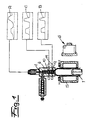
- a method for the extrusion of tubular preforms 1 is shown, which emerge from one of a mandrel 2 and a nozzle ring 3 limited nozzle gap of an extrusion head 4 and are expanded in a blow mold 5 into barrels 6 with a round cross-section.
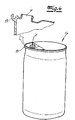
- compression collar barrels can be produced, the their upper end are provided with a bung opening 7 and at its outer periphery have a cross-sectionally L-shaped collar 8 (Fig. 4).
- Such barrels are also referred to as L-ring barrels.
- the collar as well as the lower and upper connection area form a critical area for the performance characteristics of the barrel.
- the tubular preforms emerge from the annular nozzle gap of the extrusion head 4 in a thermopiastified state.
- the width of the nozzle gap is changed during the extrusion of the preforms by an adjusting movement of the mandrel 2 and / or the nozzle ring 3.
- the cross-sectional geometry of a arranged in the extrusion head and the nozzle gap circumferentially limiting elastically deformable sleeve 9 during the extrusion of the preforms 1 is changed.
- the sleeve 9 is for example made of metal and is thin-walled. It could also consist of two or more layers.
- the sleeve can be arranged in the flow channel dom- or nozzle ring side.
- Fassab gleich means in the exemplary embodiment, the head portion of the barrels optionally with one or more bung openings and an annular collar.
- the deformation of the sleeve 9 and the adjusting movements of the additional element 10 are coordinated so that the upper end of the widened in the blow mold barrels 6 and the transition region of the barrels between drum base and drum casing in the circumferential direction has no thickness deviations from default values.
- the elastic sleeve 9 is brought into a substantially cylindrical shape in accordance with a control program running with the preform extrusion when a middle section of the preforms is extruded. If necessary, the shape is corrected so as to deviate from the cylindrical shape in such a way that a uniform melt distribution in the circumferential direction of the gap is established.
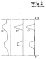
- the preforms 1 have a substantially uniform wall thickness in this area. This shows the section shown in Fig. 3a.
- the end-side Vorformlingsabschnifte which are widened in the blow mold into a drum base or to the upper drum end, correspondingly have a wall thickness distribution, which is shown in Fig. 3b.
- the thick-walled sections of the preforms are assigned to the offset by 90 ° to the dividing plane of the blow mold halves areas that are subject to a particularly strong stretching in the blow mold. It has now been found that slight changes in thickness can still occur in the top and bottom regions of a plastic barrel if the melt distribution in the preforms is influenced only by using an elastically deformable sleeve 9. By additional program-controlled adjusting movements of the additional element 10, the melt profile of the preforms can be corrected in the beginning and end sections.
- the correspondingly corrected melt profile is shown in FIG. 3c.
- the wall thickness can also be influenced by the additional element 10 with a corresponding design.
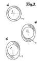
- the elastically deformable sleeve 9 is deformed by two opposing force drives 11 whose adjusting movements exert tensile and / or compressive forces on the sleeve 9 in a deformation axis oriented radially to the central axis of the mandrel.
- the sleeve 9 is supported radially movably in the nozzle housing (FIG. 6).
- the additional element 10 acts at least on sections of the nozzle gap, which are associated with deformation-neutral regions of the elastically deformable sleeve. Deformation-neutral areas are those areas which are only slightly deformable under the action of the power drives 11.
- a further elastically deformable sleeve 13 may be used, which also circumferentially bounds the nozzle gap and is deformed during the extrusion of the starting and end sections of the preforms by actuation of at least one actuator 14, 14 'acting on the sleeve.
- two axially adjustable actuators 14,14 'in the form of a rod 14 and a cylinder 14' are provided, which act on the mandrel-side sleeve 13 of the additional element (FIG. 5), the deformation direction of these actuators 14, 14 '. is angularly offset with respect to the deformation axis of the force acting on the first sleeve 9 power drives 11. It is understood that as a supplementary element 10 and a group of two or more elastically deformable sleeves is used.
- an additional element 10 can be used instead of an elastically deformable sleeve and horizontally or vertically adjustable slide 15, by the adjusting movement, the gap width of the nozzle gap is partially changed in the circumferential direction.
- the slider 15 is formed as a profiled sleeve and changed depending on the sliding position, the gap width of the flow channel.
- the slides can also have bypass channels 18, which influence the melt distribution on the circumference of the slide, as shown by way of example in FIG. 8. These can also be arranged in the longitudinal direction at any point of the flow channel to the nozzle outlet inside and / or outside of the flow channel.
- the actuating movements A, B of the dome 2 and acting on the elastic sleeve 9 power drives 11 are controlled by a wall thickness program.
- a program runs which controls the setting movements C of the additional element 10.
- the maximum values of the program curves B, C occur substantially simultaneously. This assumes that the power drives 11 and the additional element 10 are arranged approximately at the same height. It goes without saying that the maximum values of the program curves B, C can also be offset in time from one another depending on the arrangement of the additional element 10, that is to say that the positioning movements controlled by the program curve C can be activated sooner or later in comparison to the representation in FIG. Control circuits can be assigned to the controls, which ensure that the positioning movements are carried out by the amount specified by the control pulse.
- the cross-sectional geometry of an elastically deformable sleeve 9 limiting the nozzle gap on the circumference is changed by controlled setting movements of diametrically arranged first actuating devices 16 during the extrusion of the preforms.
- first actuating devices 16 power drives 11 are used, which are connected to the sleeve 9 in a tension-proof and pressure-tight manner.
- FIG. 7 shows that the power drives or the group of first actuating devices 16 on the one hand and the group of second actuating devices 17 are aligned such that the force acting direction of the first actuating device and the force acting direction of the second actuating device are aligned at right angles to one another.
- the program control shown in FIG. 2 is also suitable for operating the extrusion head shown in FIG. 7 with the proviso that the positioning movements of the separately controlled second setting devices 17 are controlled according to the program curve C, while the setting movements of the first adjusting devices 16 of FIG Follow program curve B.
Landscapes
- Engineering & Computer Science (AREA)
- Mechanical Engineering (AREA)
- Manufacturing & Machinery (AREA)
- Blow-Moulding Or Thermoforming Of Plastics Or The Like (AREA)
- Processing And Handling Of Plastics And Other Materials For Molding In General (AREA)
Applications Claiming Priority (1)
| Application Number | Priority Date | Filing Date | Title |
|---|---|---|---|
| DE102006013302.1A DE102006013302B4 (de) | 2006-03-21 | 2006-03-21 | Extrusionsblasverfahren für Kunststofffässer |
Publications (3)
| Publication Number | Publication Date |
|---|---|
| EP1837156A2 true EP1837156A2 (fr) | 2007-09-26 |
| EP1837156A3 EP1837156A3 (fr) | 2010-04-28 |
| EP1837156B1 EP1837156B1 (fr) | 2017-06-21 |
Family
ID=38229203
Family Applications (1)
| Application Number | Title | Priority Date | Filing Date |
|---|---|---|---|
| EP07005674.2A Not-in-force EP1837156B1 (fr) | 2006-03-21 | 2007-03-20 | Procédé d'extrusion pour préformes en plastique |
Country Status (4)
| Country | Link |
|---|---|
| US (1) | US20070278721A1 (fr) |
| EP (1) | EP1837156B1 (fr) |
| CA (1) | CA2582193A1 (fr) |
| DE (1) | DE102006013302B4 (fr) |
Cited By (4)
| Publication number | Priority date | Publication date | Assignee | Title |
|---|---|---|---|---|
| WO2013021245A1 (fr) * | 2011-08-10 | 2013-02-14 | Deepak Poddar | Filière d'extrusion réglable et procédé pour extruder un tube |
| EP2842718A3 (fr) * | 2013-08-30 | 2015-04-15 | Harald Feuerherm | Outil d'extrusion destiné à la production de préformes en forme de tuyau |
| RU2614868C1 (ru) * | 2015-10-28 | 2017-03-30 | Федеральное государственное бюджетное образовательное учреждение высшего профессионального образования "Московский авиационный институт (национальный исследовательский университет)" (МАИ) | Экструзионная головка для изготовления полимерной рукавной пленки |
| CN112339249A (zh) * | 2020-10-09 | 2021-02-09 | 长沙水星包装有限公司 | 综合性水桶挤吹成型设备 |
Families Citing this family (5)
| Publication number | Priority date | Publication date | Assignee | Title |
|---|---|---|---|---|
| US20170326777A1 (en) * | 2014-10-20 | 2017-11-16 | Vinidex Pty Limited | An Extrusion Tooling for Pipe Extrusion |
| DE102015105538B4 (de) * | 2015-04-10 | 2016-12-22 | Harald Feuerherm | Verfahren zur Extrusion von Vorformlingen, die durch Blasformen zu Kunststoffhohlkörpern aufgeweitet werden |
| JP6746339B2 (ja) * | 2016-03-28 | 2020-08-26 | 住友重機械モダン株式会社 | フィルム成形装置 |
| CN113306118A (zh) * | 2020-02-27 | 2021-08-27 | 安徽中浩医用塑业有限公司 | 一种塑料桶生产用吹塑装置 |
| DE102023103235A1 (de) * | 2023-02-10 | 2024-08-14 | KraussMaffei Extrusion GmbH | Extrusionswerkzeug und Extrusionsanlage |
Citations (3)
| Publication number | Priority date | Publication date | Assignee | Title |
|---|---|---|---|---|
| EP0885711B1 (fr) | 1997-06-12 | 1999-07-28 | Harald Feuerherm | Tête d'extrusion pour un appareil d'extrusion-soufflage d'objets creux, notamment des réservoirs de carburant |
| WO1999044805A1 (fr) | 1998-03-05 | 1999-09-10 | Mauser-Werke Gmbh | Tete d'extrusion |
| EP0945245A1 (fr) | 1998-03-27 | 1999-09-29 | Harald Feuerherm | Procédé de moulage de corps creux par extrusion soufflage et filière d'extrusion pour réaliser ce procédé |
Family Cites Families (6)
| Publication number | Priority date | Publication date | Assignee | Title |
|---|---|---|---|---|
| US6024557A (en) * | 1997-06-12 | 2000-02-15 | Feuerherm; Harald | Extrusion head for blow-molding apparatus |
| AU4899299A (en) * | 1998-05-28 | 1999-12-13 | Mauser-Werke Gmbh | Method and device for producing plastic hollow bodies and plastic hollow bodies produced by means of same |
| EP1167417A4 (fr) | 1999-01-28 | 2002-11-06 | Takeda Chemical Industries Ltd | Vinylesters retardateurs de flamme, resines et compositions de resines contenant lesdits vinylesters, et produits durcis obtenus a partir de ceux-ci |
| DE19904199C2 (de) * | 1999-02-03 | 2001-09-06 | Harald Feuerherm | Strangpreßkopf zum Extrusionsblasformen von Kunststoffbehältern |
| DE19929381C2 (de) * | 1999-06-25 | 2001-08-23 | Harald Feuerherm | Verfahren zum Einrichten einer Ringspaltdüse zur Herstellung von schlauchförmigen Vorformlingen, die in einer Blasform zu Kunststoffbehältern aufgeweitet werden |
| US6285169B1 (en) * | 2001-02-12 | 2001-09-04 | Power Standards Lab. | Sag generator with switch-mode impedance |
-
2006
- 2006-03-21 DE DE102006013302.1A patent/DE102006013302B4/de not_active Expired - Fee Related
-
2007
- 2007-03-19 CA CA002582193A patent/CA2582193A1/fr not_active Abandoned
- 2007-03-20 EP EP07005674.2A patent/EP1837156B1/fr not_active Not-in-force
- 2007-03-21 US US11/726,224 patent/US20070278721A1/en not_active Abandoned
Patent Citations (4)
| Publication number | Priority date | Publication date | Assignee | Title |
|---|---|---|---|---|
| EP0885711B1 (fr) | 1997-06-12 | 1999-07-28 | Harald Feuerherm | Tête d'extrusion pour un appareil d'extrusion-soufflage d'objets creux, notamment des réservoirs de carburant |
| WO1999044805A1 (fr) | 1998-03-05 | 1999-09-10 | Mauser-Werke Gmbh | Tete d'extrusion |
| EP0945245A1 (fr) | 1998-03-27 | 1999-09-29 | Harald Feuerherm | Procédé de moulage de corps creux par extrusion soufflage et filière d'extrusion pour réaliser ce procédé |
| US6284169B1 (en) | 1998-03-27 | 2001-09-04 | Harald Feuerherm | Method of extrusion blow molding of a hollow body |
Non-Patent Citations (1)
| Title |
|---|
| PLASTVERARBEITER, vol. 32, no. 3, 1981, pages 326 - 330 |
Cited By (5)
| Publication number | Priority date | Publication date | Assignee | Title |
|---|---|---|---|---|
| WO2013021245A1 (fr) * | 2011-08-10 | 2013-02-14 | Deepak Poddar | Filière d'extrusion réglable et procédé pour extruder un tube |
| EP2842718A3 (fr) * | 2013-08-30 | 2015-04-15 | Harald Feuerherm | Outil d'extrusion destiné à la production de préformes en forme de tuyau |
| RU2614868C1 (ru) * | 2015-10-28 | 2017-03-30 | Федеральное государственное бюджетное образовательное учреждение высшего профессионального образования "Московский авиационный институт (национальный исследовательский университет)" (МАИ) | Экструзионная головка для изготовления полимерной рукавной пленки |
| CN112339249A (zh) * | 2020-10-09 | 2021-02-09 | 长沙水星包装有限公司 | 综合性水桶挤吹成型设备 |
| CN112339249B (zh) * | 2020-10-09 | 2021-08-24 | 长沙水星包装有限公司 | 综合性水桶挤吹成型设备 |
Also Published As
| Publication number | Publication date |
|---|---|
| CA2582193A1 (fr) | 2007-09-21 |
| DE102006013302B4 (de) | 2022-03-17 |
| US20070278721A1 (en) | 2007-12-06 |
| EP1837156A3 (fr) | 2010-04-28 |
| EP1837156B1 (fr) | 2017-06-21 |
| DE102006013302A1 (de) | 2007-09-27 |
Similar Documents
| Publication | Publication Date | Title |
|---|---|---|
| EP1837156B1 (fr) | Procédé d'extrusion pour préformes en plastique | |
| EP0945245B1 (fr) | Procédé de moulage de corps creux par extrusion soufflage | |
| DE2654001C2 (de) | Vorrichtung zum Herstellen von aus thermoplastischem Kunstoff bestehenden Hohlkörpern | |
| EP2176054B1 (fr) | Dispositif et procédé de soufflage destiné à dilater des récipients | |
| DE102006027254B4 (de) | Verfahren zur Herstellung von Hohlkörpern aus thermoplastischem Kunststoff durch Extrusionsblasformen | |
| EP1970190A2 (fr) | Dispositif de traitement de récipients | |
| DE2604247A1 (de) | Verfahren zum blasformen sowie hohlkoerperblasmaschine | |
| DE19854249C2 (de) | Verfahren und Vorrichtung zum Extrusionsblasformen von Kunststoffbehältern mit unterschiedlichen Behälterquerschnitten | |
| DE3031333A1 (de) | Verfahren zur partiellen wanddickensteuerung am umfang von durch extrudieren hochmolekularer thermoplastischer schmelzen gebildeten schlaeuchen sowie vorrichtung zur durchfuehrung des verfahrens | |
| DE3439285A1 (de) | Verfahren und vorrichtung zum herstellen eines hohlen kunststoffkoerpers | |
| EP2915651A1 (fr) | Procédé de fabrication de corps creux en matière plastique formés par soufflage et tête d'extrusion multiple permettant de réaliser le procédé | |
| EP2705941B1 (fr) | Procédé de fabrication de corps creux en matière plastique formés par soufflage et tête d'extrusion multiple permettant de réaliser le procédé | |
| EP1610939B1 (fr) | Procede pour mouler par soufflage des corps creux en matiere thermoplastique | |
| DE202006013751U1 (de) | Vorrichtung zur Herstellung von bandförmigen Kunststoffvorformlingen | |
| EP3558631B2 (fr) | Procédé et dispositif pour le moulage par soufflage de récipients présentant une partie de fond mobile | |
| EP3558632B1 (fr) | Procédé et dispositif pour le moulage par soufflage de contenants à l'aide d'une partie inférieure mobile | |
| WO2012034614A1 (fr) | Outil de moulage par soufflage comportant une partie de moule pouvant être soulevée | |
| EP1063074B1 (fr) | Procédé pour configurer une buse annulaire pour la fabrication de préformes tubulaires | |
| EP4124440B1 (fr) | Système d'outil à filière et dispositif d'extrusion-soufflage | |
| EP1388406B1 (fr) | Procédé et dispositif pour la fabrication par soufflage de corps creux en matière thermoplastique | |
| EP1129838B1 (fr) | Dispositif pour fabriquer des articles de forme creuse en matière thermoplastique par aspiration et soufflage | |
| EP2225083A1 (fr) | Pré-ébauche en forme de tuyau flexible, fabrication de pièces moulées-soufflées et procédé ainsi que dispositif de fabrication de la pré-ébauche | |
| DE60110694T2 (de) | Verfahren und Form zur Herstellung eines Balges, durch das Verfahren herstellbarer Vorformling, und Balg | |
| EP4069492B1 (fr) | Moule de soufflage, moule de soufflage à étirage et procédé de formation d'un récipient | |
| DE102018119640A1 (de) | Blasformverfahren |
Legal Events
| Date | Code | Title | Description |
|---|---|---|---|
| PUAI | Public reference made under article 153(3) epc to a published international application that has entered the european phase |
Free format text: ORIGINAL CODE: 0009012 |
|
| AK | Designated contracting states |
Kind code of ref document: A2 Designated state(s): AT BE BG CH CY CZ DE DK EE ES FI FR GB GR HU IE IS IT LI LT LU LV MC MT NL PL PT RO SE SI SK TR |
|
| AX | Request for extension of the european patent |
Extension state: AL BA HR MK YU |
|
| PUAL | Search report despatched |
Free format text: ORIGINAL CODE: 0009013 |
|
| AK | Designated contracting states |
Kind code of ref document: A3 Designated state(s): AT BE BG CH CY CZ DE DK EE ES FI FR GB GR HU IE IS IT LI LT LU LV MC MT NL PL PT RO SE SI SK TR |
|
| AX | Request for extension of the european patent |
Extension state: AL BA HR MK RS |
|
| 17P | Request for examination filed |
Effective date: 20101026 |
|
| 17Q | First examination report despatched |
Effective date: 20101208 |
|
| AKX | Designation fees paid |
Designated state(s): AT BE BG CH CY CZ DE DK EE ES FI FR GB GR HU IE IS IT LI LT LU LV MC MT NL PL PT RO SE SI SK TR |
|
| GRAP | Despatch of communication of intention to grant a patent |
Free format text: ORIGINAL CODE: EPIDOSNIGR1 |
|
| INTG | Intention to grant announced |
Effective date: 20161222 |
|
| GRAS | Grant fee paid |
Free format text: ORIGINAL CODE: EPIDOSNIGR3 |
|
| GRAA | (expected) grant |
Free format text: ORIGINAL CODE: 0009210 |
|
| AK | Designated contracting states |
Kind code of ref document: B1 Designated state(s): AT BE BG CH CY CZ DE DK EE ES FI FR GB GR HU IE IS IT LI LT LU LV MC MT NL PL PT RO SE SI SK TR |
|
| RAP1 | Party data changed (applicant data changed or rights of an application transferred) |
Owner name: FEUERHERM, HARALD |
|
| REG | Reference to a national code |
Ref country code: GB Ref legal event code: FG4D Free format text: NOT ENGLISH |
|
| RIN1 | Information on inventor provided before grant (corrected) |
Inventor name: FEUERHERM, HARALD |
|
| REG | Reference to a national code |
Ref country code: DE Ref legal event code: R081 Ref document number: 502007015710 Country of ref document: DE Owner name: FEUERHERM, MAX, DE Free format text: FORMER OWNER: FEUERHERM, HARALD, DIPL.-ING., 53840 TROISDORF, DE |
|
| REG | Reference to a national code |
Ref country code: CH Ref legal event code: EP |
|
| REG | Reference to a national code |
Ref country code: IE Ref legal event code: FG4D Free format text: LANGUAGE OF EP DOCUMENT: GERMAN |
|
| REG | Reference to a national code |
Ref country code: AT Ref legal event code: REF Ref document number: 902538 Country of ref document: AT Kind code of ref document: T Effective date: 20170715 |
|
| REG | Reference to a national code |
Ref country code: DE Ref legal event code: R096 Ref document number: 502007015710 Country of ref document: DE |
|
| REG | Reference to a national code |
Ref country code: NL Ref legal event code: MP Effective date: 20170621 |
|
| PG25 | Lapsed in a contracting state [announced via postgrant information from national office to epo] |
Ref country code: GR Free format text: LAPSE BECAUSE OF FAILURE TO SUBMIT A TRANSLATION OF THE DESCRIPTION OR TO PAY THE FEE WITHIN THE PRESCRIBED TIME-LIMIT Effective date: 20170922 Ref country code: LT Free format text: LAPSE BECAUSE OF FAILURE TO SUBMIT A TRANSLATION OF THE DESCRIPTION OR TO PAY THE FEE WITHIN THE PRESCRIBED TIME-LIMIT Effective date: 20170621 Ref country code: FI Free format text: LAPSE BECAUSE OF FAILURE TO SUBMIT A TRANSLATION OF THE DESCRIPTION OR TO PAY THE FEE WITHIN THE PRESCRIBED TIME-LIMIT Effective date: 20170621 |
|
| REG | Reference to a national code |
Ref country code: LT Ref legal event code: MG4D |
|
| PG25 | Lapsed in a contracting state [announced via postgrant information from national office to epo] |
Ref country code: NL Free format text: LAPSE BECAUSE OF FAILURE TO SUBMIT A TRANSLATION OF THE DESCRIPTION OR TO PAY THE FEE WITHIN THE PRESCRIBED TIME-LIMIT Effective date: 20170621 Ref country code: SE Free format text: LAPSE BECAUSE OF FAILURE TO SUBMIT A TRANSLATION OF THE DESCRIPTION OR TO PAY THE FEE WITHIN THE PRESCRIBED TIME-LIMIT Effective date: 20170621 Ref country code: BG Free format text: LAPSE BECAUSE OF FAILURE TO SUBMIT A TRANSLATION OF THE DESCRIPTION OR TO PAY THE FEE WITHIN THE PRESCRIBED TIME-LIMIT Effective date: 20170921 Ref country code: LV Free format text: LAPSE BECAUSE OF FAILURE TO SUBMIT A TRANSLATION OF THE DESCRIPTION OR TO PAY THE FEE WITHIN THE PRESCRIBED TIME-LIMIT Effective date: 20170621 |
|
| PG25 | Lapsed in a contracting state [announced via postgrant information from national office to epo] |
Ref country code: CZ Free format text: LAPSE BECAUSE OF FAILURE TO SUBMIT A TRANSLATION OF THE DESCRIPTION OR TO PAY THE FEE WITHIN THE PRESCRIBED TIME-LIMIT Effective date: 20170621 Ref country code: SK Free format text: LAPSE BECAUSE OF FAILURE TO SUBMIT A TRANSLATION OF THE DESCRIPTION OR TO PAY THE FEE WITHIN THE PRESCRIBED TIME-LIMIT Effective date: 20170621 Ref country code: EE Free format text: LAPSE BECAUSE OF FAILURE TO SUBMIT A TRANSLATION OF THE DESCRIPTION OR TO PAY THE FEE WITHIN THE PRESCRIBED TIME-LIMIT Effective date: 20170621 Ref country code: RO Free format text: LAPSE BECAUSE OF FAILURE TO SUBMIT A TRANSLATION OF THE DESCRIPTION OR TO PAY THE FEE WITHIN THE PRESCRIBED TIME-LIMIT Effective date: 20170621 |
|
| PG25 | Lapsed in a contracting state [announced via postgrant information from national office to epo] |
Ref country code: PL Free format text: LAPSE BECAUSE OF FAILURE TO SUBMIT A TRANSLATION OF THE DESCRIPTION OR TO PAY THE FEE WITHIN THE PRESCRIBED TIME-LIMIT Effective date: 20170621 Ref country code: ES Free format text: LAPSE BECAUSE OF FAILURE TO SUBMIT A TRANSLATION OF THE DESCRIPTION OR TO PAY THE FEE WITHIN THE PRESCRIBED TIME-LIMIT Effective date: 20170621 Ref country code: IT Free format text: LAPSE BECAUSE OF FAILURE TO SUBMIT A TRANSLATION OF THE DESCRIPTION OR TO PAY THE FEE WITHIN THE PRESCRIBED TIME-LIMIT Effective date: 20170621 Ref country code: IS Free format text: LAPSE BECAUSE OF FAILURE TO SUBMIT A TRANSLATION OF THE DESCRIPTION OR TO PAY THE FEE WITHIN THE PRESCRIBED TIME-LIMIT Effective date: 20171021 |
|
| REG | Reference to a national code |
Ref country code: DE Ref legal event code: R097 Ref document number: 502007015710 Country of ref document: DE |
|
| REG | Reference to a national code |
Ref country code: FR Ref legal event code: PLFP Year of fee payment: 12 |
|
| PLBE | No opposition filed within time limit |
Free format text: ORIGINAL CODE: 0009261 |
|
| STAA | Information on the status of an ep patent application or granted ep patent |
Free format text: STATUS: NO OPPOSITION FILED WITHIN TIME LIMIT |
|
| PG25 | Lapsed in a contracting state [announced via postgrant information from national office to epo] |
Ref country code: DK Free format text: LAPSE BECAUSE OF FAILURE TO SUBMIT A TRANSLATION OF THE DESCRIPTION OR TO PAY THE FEE WITHIN THE PRESCRIBED TIME-LIMIT Effective date: 20170621 |
|
| 26N | No opposition filed |
Effective date: 20180322 |
|
| PG25 | Lapsed in a contracting state [announced via postgrant information from national office to epo] |
Ref country code: SI Free format text: LAPSE BECAUSE OF FAILURE TO SUBMIT A TRANSLATION OF THE DESCRIPTION OR TO PAY THE FEE WITHIN THE PRESCRIBED TIME-LIMIT Effective date: 20170621 |
|
| PG25 | Lapsed in a contracting state [announced via postgrant information from national office to epo] |
Ref country code: MT Free format text: LAPSE BECAUSE OF FAILURE TO SUBMIT A TRANSLATION OF THE DESCRIPTION OR TO PAY THE FEE WITHIN THE PRESCRIBED TIME-LIMIT Effective date: 20170621 |
|
| REG | Reference to a national code |
Ref country code: CH Ref legal event code: PL |
|
| REG | Reference to a national code |
Ref country code: DE Ref legal event code: R079 Ref document number: 502007015710 Country of ref document: DE Free format text: PREVIOUS MAIN CLASS: B29C0047220000 Ipc: B29C0048325000 |
|
| PG25 | Lapsed in a contracting state [announced via postgrant information from national office to epo] |
Ref country code: MC Free format text: LAPSE BECAUSE OF FAILURE TO SUBMIT A TRANSLATION OF THE DESCRIPTION OR TO PAY THE FEE WITHIN THE PRESCRIBED TIME-LIMIT Effective date: 20170621 |
|
| REG | Reference to a national code |
Ref country code: BE Ref legal event code: MM Effective date: 20180331 |
|
| REG | Reference to a national code |
Ref country code: IE Ref legal event code: MM4A |
|
| PG25 | Lapsed in a contracting state [announced via postgrant information from national office to epo] |
Ref country code: LU Free format text: LAPSE BECAUSE OF NON-PAYMENT OF DUE FEES Effective date: 20180320 |
|
| PG25 | Lapsed in a contracting state [announced via postgrant information from national office to epo] |
Ref country code: IE Free format text: LAPSE BECAUSE OF NON-PAYMENT OF DUE FEES Effective date: 20180320 |
|
| PG25 | Lapsed in a contracting state [announced via postgrant information from national office to epo] |
Ref country code: LI Free format text: LAPSE BECAUSE OF NON-PAYMENT OF DUE FEES Effective date: 20180331 Ref country code: BE Free format text: LAPSE BECAUSE OF NON-PAYMENT OF DUE FEES Effective date: 20180331 Ref country code: CH Free format text: LAPSE BECAUSE OF NON-PAYMENT OF DUE FEES Effective date: 20180331 |
|
| REG | Reference to a national code |
Ref country code: AT Ref legal event code: MM01 Ref document number: 902538 Country of ref document: AT Kind code of ref document: T Effective date: 20180320 |
|
| PG25 | Lapsed in a contracting state [announced via postgrant information from national office to epo] |
Ref country code: AT Free format text: LAPSE BECAUSE OF NON-PAYMENT OF DUE FEES Effective date: 20180320 |
|
| REG | Reference to a national code |
Ref country code: DE Ref legal event code: R082 Ref document number: 502007015710 Country of ref document: DE Representative=s name: ANDREJEWSKI HONKE PATENT- UND RECHTSANWAELTE P, DE Ref country code: DE Ref legal event code: R081 Ref document number: 502007015710 Country of ref document: DE Owner name: FEUERHERM, MAX, DE Free format text: FORMER OWNER: FEUERHERM, HARALD, DIPL.-ING., 53840 TROISDORF, DE |
|
| PG25 | Lapsed in a contracting state [announced via postgrant information from national office to epo] |
Ref country code: TR Free format text: LAPSE BECAUSE OF FAILURE TO SUBMIT A TRANSLATION OF THE DESCRIPTION OR TO PAY THE FEE WITHIN THE PRESCRIBED TIME-LIMIT Effective date: 20170621 |
|
| PG25 | Lapsed in a contracting state [announced via postgrant information from national office to epo] |
Ref country code: PT Free format text: LAPSE BECAUSE OF FAILURE TO SUBMIT A TRANSLATION OF THE DESCRIPTION OR TO PAY THE FEE WITHIN THE PRESCRIBED TIME-LIMIT Effective date: 20170621 Ref country code: HU Free format text: LAPSE BECAUSE OF FAILURE TO SUBMIT A TRANSLATION OF THE DESCRIPTION OR TO PAY THE FEE WITHIN THE PRESCRIBED TIME-LIMIT; INVALID AB INITIO Effective date: 20070320 |
|
| PG25 | Lapsed in a contracting state [announced via postgrant information from national office to epo] |
Ref country code: CY Free format text: LAPSE BECAUSE OF FAILURE TO SUBMIT A TRANSLATION OF THE DESCRIPTION OR TO PAY THE FEE WITHIN THE PRESCRIBED TIME-LIMIT Effective date: 20170621 |
|
| REG | Reference to a national code |
Ref country code: GB Ref legal event code: 732E Free format text: REGISTERED BETWEEN 20200618 AND 20200624 |
|
| PGFP | Annual fee paid to national office [announced via postgrant information from national office to epo] |
Ref country code: FR Payment date: 20210323 Year of fee payment: 15 |
|
| PGFP | Annual fee paid to national office [announced via postgrant information from national office to epo] |
Ref country code: GB Payment date: 20210325 Year of fee payment: 15 |
|
| PGFP | Annual fee paid to national office [announced via postgrant information from national office to epo] |
Ref country code: DE Payment date: 20220210 Year of fee payment: 16 |
|
| GBPC | Gb: european patent ceased through non-payment of renewal fee |
Effective date: 20220320 |
|
| PG25 | Lapsed in a contracting state [announced via postgrant information from national office to epo] |
Ref country code: GB Free format text: LAPSE BECAUSE OF NON-PAYMENT OF DUE FEES Effective date: 20220320 Ref country code: FR Free format text: LAPSE BECAUSE OF NON-PAYMENT OF DUE FEES Effective date: 20220331 |
|
| REG | Reference to a national code |
Ref country code: DE Ref legal event code: R119 Ref document number: 502007015710 Country of ref document: DE |
|
| PG25 | Lapsed in a contracting state [announced via postgrant information from national office to epo] |
Ref country code: DE Free format text: LAPSE BECAUSE OF NON-PAYMENT OF DUE FEES Effective date: 20231003 |