EP2176837B2 - Dispositif de transmission et procédé pour la transmission d'une position actuelle d'un véhicule à une centrale d'exploitation - Google Patents
Dispositif de transmission et procédé pour la transmission d'une position actuelle d'un véhicule à une centrale d'exploitation Download PDFInfo
- Publication number
- EP2176837B2 EP2176837B2 EP08785917.9A EP08785917A EP2176837B2 EP 2176837 B2 EP2176837 B2 EP 2176837B2 EP 08785917 A EP08785917 A EP 08785917A EP 2176837 B2 EP2176837 B2 EP 2176837B2
- Authority
- EP
- European Patent Office
- Prior art keywords
- vehicle
- marking
- evaluation
- sensor
- information
- Prior art date
- Legal status (The legal status is an assumption and is not a legal conclusion. Google has not performed a legal analysis and makes no representation as to the accuracy of the status listed.)
- Not-in-force
Links
- 238000011156 evaluation Methods 0.000 title claims description 36
- 230000005540 biological transmission Effects 0.000 title claims description 33
- 238000000034 method Methods 0.000 title claims description 8
- 230000003287 optical effect Effects 0.000 claims description 15
- 238000012545 processing Methods 0.000 claims description 8
- 238000001514 detection method Methods 0.000 claims description 6
- 238000011161 development Methods 0.000 description 4
- 230000005672 electromagnetic field Effects 0.000 description 3
- 239000003550 marker Substances 0.000 description 2
- 239000013589 supplement Substances 0.000 description 2
- 208000012868 Overgrowth Diseases 0.000 description 1
- 238000004891 communication Methods 0.000 description 1
- 238000005516 engineering process Methods 0.000 description 1
- 230000007613 environmental effect Effects 0.000 description 1
- 238000004519 manufacturing process Methods 0.000 description 1
- 238000012552 review Methods 0.000 description 1
- 230000000007 visual effect Effects 0.000 description 1
Images

Classifications
-
- G—PHYSICS
- G07—CHECKING-DEVICES
- G07C—TIME OR ATTENDANCE REGISTERS; REGISTERING OR INDICATING THE WORKING OF MACHINES; GENERATING RANDOM NUMBERS; VOTING OR LOTTERY APPARATUS; ARRANGEMENTS, SYSTEMS OR APPARATUS FOR CHECKING NOT PROVIDED FOR ELSEWHERE
- G07C5/00—Registering or indicating the working of vehicles
- G07C5/008—Registering or indicating the working of vehicles communicating information to a remotely located station
-
- G—PHYSICS
- G07—CHECKING-DEVICES
- G07B—TICKET-ISSUING APPARATUS; FARE-REGISTERING APPARATUS; FRANKING APPARATUS
- G07B15/00—Arrangements or apparatus for collecting fares, tolls or entrance fees at one or more control points
- G07B15/06—Arrangements for road pricing or congestion charging of vehicles or vehicle users, e.g. automatic toll systems
- G07B15/063—Arrangements for road pricing or congestion charging of vehicles or vehicle users, e.g. automatic toll systems using wireless information transmission between the vehicle and a fixed station
Definitions
- the present invention relates to a transmission device and a method for transmitting a current position of a vehicle to an evaluation center according to the preamble of independent claim 1 or 7, as shown in DE 10 2005 058 033 A1 known.
- the WO 2004/027730 A describes a territorial overgrowth system that detects and analyzes license plates of motor vehicles.
- toll bollards are often referred to as toll bollards.
- electronic toll collection systems therefore include fixed control devices for recognizing and identifying toll bouncers.
- the stationary control devices are usually designed to detect the absence of an OBU unit or the incorrect functioning of an OBU unit on a toll vehicle in its immediate vicinity.
- the stationary control devices are designed as toll bridges.
- the invention provides a transmission device having the features of claim 1 and a method having the features of claim 7.
- the invention is based on the finding that toll bumpers are recognizable and identifiable without the use of stationary control devices by equipping a number of vehicles with a transmission device according to the invention which is designed to display an optical and electromagnetic marking from a foreign vehicle together with its own vehicle position to transmit an evaluation center.
- the evaluation center recognizes the identity of the foreign vehicle based on the information transmitted by the vehicle and queries which data is received by the detected foreign vehicle within a predetermined period of time. Subsequently, the evaluation center determines from the data the current own vehicle position specified by the foreign vehicle itself. The own vehicle position indicated by the foreign vehicle itself is compared with the reported position of the vehicle with the transmission device.
- the evaluation center determines a contradiction between the position transmitted by the vehicle with the transmission device and the current own vehicle position transmitted by the other vehicle, it notifies the toll operator.
- the other vehicle can then be checked by the toll operator in terms of a possible manipulation of the OBU unit.
- the position information may be a local coordinate, a road segment or a geographical zone.
- the position information can thus only be an approximate information about the current position of the control vehicle.
- a preferred embodiment of the invention has the advantage that a vehicle equipped with the transmission device according to the invention is not recognizable as such. An encounter with such a vehicle can therefore not be avoided by a toll-bumper. An enabled by the invention review of a toll vehicle is therefore time and place independent. This is an advantage over toll bridges whose location is quickly known to a driver and which are easily navigable with this knowledge.
- the vehicle equipped with the transmission device may also be indicated as such to other vehicles by markings such as special stickers, if necessary for reasons of data protection law.
- a transmission device not according to the invention in its simplest embodiment only has to have a sensor and / or evaluation device for reading an electromagnetic marking and a transmitting device for transmitting a long-distance signal, it can be produced inexpensively.
- the complex evaluation devices for identifying the foreign vehicle and for determining whether the foreign vehicle is a toll-bumper are arranged in this case only at the evaluation center. This makes it possible to equip a high number of vehicles in a cost effective manner with the transmission device.
- the sensor and / or evaluation device can only be an evaluation device.
- This evaluation device is then designed to evaluate data provided by a vehicle-specific sensor device, for example a video signal recorded by an on-board camera device, with regard to the marking of the foreign vehicle.
- the evaluation device receives the environmental data from a lane departure warning system (Lane Departure Warning System) and then evaluates them accordingly.
- a lane departure warning system LiD Warning System
- the equipment of a vehicle with the transmission device according to the invention is therefore cheaper with high road network coverage than the usual stationary toll bridges.
- the desired degree of coverage can be adjusted by the number of vehicles equipped with the transmission device and their region.
- any number of vehicles is equipped with the transmission device according to the invention, which allows reading the optical and electromagnetic mark and communication with the data center of the toll operator.
- the equipment of the vehicle with the transmission device can be executed as an extension to an existing on-vehicle OBU unit (on-board unit). This additionally reduces the cost of such a transmission device.
- the senor and / or evaluation device has a laser and detection device for the visual detection of at least one partial surface of the foreign vehicle.
- a sensor device can be produced in a cost-effective manner and is well suited for reading an optical marking of a foreign vehicle.
- the optical marking of the other vehicle is a license plate. Since vehicles must be conventionally equipped with a license plate, thus already recognizable for the transmission device marking on each other vehicle is present.
- the transmission device can be designed as an ANPR (Automatic Number Plate Recognition) system or as a simple camera with an image processing device. The described embodiment of the transmission device can thus be implemented inexpensively.
- the senor and / or evaluation device is additionally designed to determine a distance between the vehicle and the foreign vehicle and / or a speed of the foreign vehicle and a corresponding distance and / or speed signal to an on-board warning and / or control device To provide, for example, to a collision warning to a driver assistance system, to an emergency braking system and / or to an airbag deployment system.
- an on-board warning and / or control device To provide, for example, to a collision warning to a driver assistance system, to an emergency braking system and / or to an airbag deployment system.
- the senor and / or evaluation device is additionally designed to record an environment of the vehicle and to provide it as a video signal to an on-board display device, for example to a parking aid, a reversing aid and / or a blind spot display aid.
- an on-board display device for example to a parking aid, a reversing aid and / or a blind spot display aid.
- the senor and / or evaluation device can additionally be designed to record an environment of the vehicle and as a video signal to an on-board evaluation device for determining a reaction of the vehicle which is advantageous with regard to the environment, for example to a driver assistance system and / or to provide a lane departure warning device (lane departure warning). Due to the multi-functionality of the sensor and / or evaluation can be additionally saved space on the vehicle.
- the senor and / or evaluation device has a reading device for generating an alternating electromagnetic field for exciting an RFID transponder (Radio Frequency Identification) and for receiving a serial number transmitted by the excited RFID transponder.
- RFID is currently used in addition to the classic features of a vehicle in some countries Vehicle identification tested.
- RFID is used to identify vehicle components in the manufacture of vehicle components.
- Another advantage is that a reader for reading an RFID transponder and the RFID transponder itself can be produced inexpensively.
- the senor and / or evaluation device has an evaluation device for determining an identity of the foreign vehicle on the basis of the optical and / or electromagnetic marking.
- the identity of the foreign vehicle can already be determined on the vehicle itself.
- the evaluation center is a toll center.
- the toll center preferably identifies the foreign vehicle on the basis of the reported optical and / or electromagnetic marker and compares the reported position of the foreign vehicle with the positions of the foreign vehicle reported for toll collection. In this way, the toll center can quickly recognize a vehicle whose OBU unit is being manipulated to determine the toll to be paid or removed from the vehicle.
- an identity of the first vehicle is determined after receipt of the long-distance signal on the basis of the marking information, and the position information is compared with a location information and / or minimum toll transmitted by the first vehicle itself to the evaluation center.
- the long-distance signals of several vehicles can be used. If the first vehicle is reported at two locations, for example, within a predetermined period of time, the evaluation center checks whether the distance traveled by the first vehicle between the two locations is not greater than a distance traveled by the first vehicle itself. Similarly, the evaluation center may determine a minimum toll for the route between the two locations and check whether the toll to be paid reported by the first vehicle itself is at least equal to that amount.
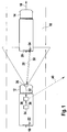
- FIG. 1 a control vehicle with an embodiment of the transmission device when reading a mark from a foreign vehicle; and chen.
- the long-distance signals of several vehicles can be used. If the first vehicle is reported at two locations, for example, within a predetermined period of time, then the evaluation center checks whether the distance covered by the first vehicle between the two locations is not greater than a distance traveled by the first vehicle itself. Similarly, the evaluation center may determine a minimum toll for the route between the two locations and check whether the toll to be paid reported by the first vehicle itself is at least equal to that amount.
- FIG. 1 shows a control vehicle with an embodiment of the transmission device when reading a mark from a foreign vehicle. Shown is a roadway 10, on which two vehicles 12 and 14 drive one behind the other in a direction of travel 16. The control vehicle 12 drives behind the other vehicle 14. In the in FIG. 1 As shown, the control vehicle 12 is adapted to read markings from the preceding foreign vehicle 14. However, the present invention is not limited to that in FIG. 1 shown embodiment limited. Alternatively or in addition, the control vehicle 12 may also be configured to determine the markings of all vehicles within a certain perimeter.
- Both vehicles 12 and 14 have number plates 18 and 20 on their rear sides.
- both vehicles 12 and 14 are each equipped with an RFID transponder (Radio Frequency Identification) 22 and 24.
- RFID transponders 22 and 24 are disposed near the rear sides of the vehicles 12 and 14, respectively.
- the RFID transponders 22 and 24 may be attached to other mounting locations of the vehicles 12 and 14 as well.
- the control vehicle 12 has on its front side a sensor device 26 with which the license plate 20 and the RFID transponder 24 of the foreign vehicle 14 can be read.
- the sensor device 26 includes a camera with a connected image processing device.
- the image processing device evaluates a video signal provided by the camera with regard to the license plate shown on the license plate 20.
- the sensor device 26 has an interrogator (reader) for generating an electromagnetic field 28.
- the electromagnetic field 28 causes the RFID transponder 24 of the foreign vehicle 14 to emit its identification number as an electromagnetic signal 30.
- the interrogator of the sensor device 26 then receives the emitted from the RFID transponder 24 electromagnetic signal 30 with the identification number.
- the identification number is then output as marking information 32 together with the identification number of the license plate 20 of the foreign vehicle 14 determined by the image processing device.
- the control vehicle 12 is equipped with a position detection device 34, which determines a current position of the control vehicle 12 on the basis of a satellite signal. A determined by the position determining means 34 current position of the Control vehicle 12 is continuously output as position information 36 to a transmitting device 38.
- the position detection device 34 is also designed in a preferred embodiment to supply a navigation system of the control vehicle 12 with information about the current position of the control vehicle 12. This multifunctionality of the position detection device 34 is associated with cost savings for the driver of the control vehicle 12.
- the transmitting device 38 receives the output position information 36 together with the marking information 32 provided by the sensor device 26.
- the transmitting device 38 then sends a long-distance signal 40 to an evaluation station (not shown).
- the long-distance signal 40 contains information about the markings 20 and 24 of the foreign vehicle 14 and about the current position of the control vehicle 12.
- FIG. 2 shows the control vehicle 12 together with the preceding foreign vehicle 14.
- the control vehicle 12 is currently transmitting the long-distance signal 40 to an evaluation center 42.
- the evaluation center 42 is in the example off FIG. 2 assigned to a system for electronic toll collection. It determines the identity of the foreign vehicle 14 on the basis of the long-distance signal 40.
- the evaluation center 42 then compares the current position reported by the control vehicle 12 with the aid of the long-distance signal 40 with the positions which the foreign vehicle 14 itself has to determine a driver to pay for the foreign vehicle 14 Toll to the evaluation center 42 sends.
- the evaluation center 42 determines that the control vehicle 12 recognizes the markings 20 and 24 of the foreign vehicle 14 at a position which deviates significantly from the current position reported by the foreign vehicle 14 itself, it issues a corresponding message to the toll operator.
- the toll operator now has the option to check the other vehicle 14 specifically for the correctness of the data reported by the other vehicle 14.
- the other vehicle 14 may still be possible sent data are made. If the foreign vehicle 14 is detected at at least two different locations within a certain time, the toll center can check whether a correct minimum distance or a correct minimum toll amount has been reported to the toll center for the distance between the two locations from the other vehicle 14.
- the sensor device 26 can also output a video signal to a display device of the control vehicle 12.
- a corresponding display device is, for example, a parking aid, a reversing aid and / or a tote-angle display aid.
- the sensor device 26 may provide a video signal to a driver assistance system and / or to a lane departure warning device.
- the sensor device 26 may also be designed to determine a distance between the control vehicle 12 and the foreign vehicle 14 and / or a speed of the foreign vehicle 14 and a corresponding distance and / or speed signal to an on-board control device, for example to a driver assistance system, to an emergency brake system and / or to an airbag deployment system.
- Such a distance and / or speed signal can also be output by the sensor device 26 to an on-board warning device, for example to a collision warning.
- the sensor device 26 can perform other functions that improve the safety of the occupants and the ride comfort for the driver of the control vehicle 12 equipped therewith. Due to the multifunctionality of the sensor device 26 of the transmission device, the number of attached to the control vehicle 12 sensors can be reduced. This eliminates the cost of the saved sensors. In addition, the available space for other components of the control vehicle 12 space is increased.
Landscapes
- Physics & Mathematics (AREA)
- General Physics & Mathematics (AREA)
- Engineering & Computer Science (AREA)
- Computer Networks & Wireless Communication (AREA)
- Business, Economics & Management (AREA)
- Finance (AREA)
- Traffic Control Systems (AREA)
- Devices For Checking Fares Or Tickets At Control Points (AREA)
- Arrangements For Transmission Of Measured Signals (AREA)
Claims (8)
- Dispositif de transmission permettant à un véhicule (12) de transmettre une position actuelle d'un autre véhicule (14) à une centrale d'exploitation (42), comportant- un dispositif à capteurs et/ou d'exploitation (26) qui est configuré pour lire une balise optique et électromagnétique (20, 24) de l'autre véhicule (14) et pour fournir une information de balise (32) correspondant à la balise optique et électromagnétique (20, 24) lue ; et- un dispositif d'émission (38) qui est configuré pour recevoir une information de position (36) concernant une position actuelle du véhicule (12) fournie par un appareil de détection de position (34) propre au véhicule ainsi que l'information de balise (32) fournie, et pour envoyer un signal à grande portée (40) contenant l'information de position (36) fournie et l'information de balise (32) fournie à la centrale d'exploitation (42) ;
caractérisé en ce que- le dispositif à capteurs et/ou d'exploitation (26) comporte un dispositif à caméra et de traitement d'images destiné à détecter visuellement au moins une surface partielle de l'autre véhicule (14) et un appareil de lecture destiné à générer un champ alternatif électromagnétique afin d'exciter un répéteur RFID (24) de l'autre véhicule (14) en tant que balise électronique (24) et à recevoir un numéro de série envoyé par le répéteur RFID (24) excité en tant qu'information de balise (32) correspondant à la balise électromagnétique (24) lue, dans lequel la balise optique (20) de l'autre véhicule (14) est une plaque d'immatriculation (20) et le numéro de série est envoyé avec l'identification de la plaque d'immatriculation (20) de l'autre véhicule (14) déterminée par le biais du dispositif de traitement d'images sous la forme de l'information de balise (32) lue ; et- la centrale d'exploitation (42) est une centrale de péage. - Dispositif de transmission selon la revendication 1, dans lequel le dispositif à capteurs et/ou d'exploitation (26) est en outre configuré pour lire une balise optique (20) de l'autre véhicule (14) et pour fournir une information de balise (32) correspondant à la balise optique (20) lue, et comporte un dispositif à laser et de détection destiné à détecter visuellement au moins une surface partielle de l'autre véhicule (14).
- Dispositif de transmission selon la revendication 1 ou 2, dans lequel le dispositif à capteurs et/ou d'exploitation (26) est en outre configuré pour déterminer une distance entre le véhicule (12) et l'autre véhicule (14) et/ou une vitesse de l'autre véhicule (14) et pour fournir un signal correspondant de distance et/ou de vitesse à un appareil d'alarme et/ou de commande propre au véhicule, par exemple à une alarme anticollision, à un système d'assistance au conducteur, à un système de freinage d'urgence et/ou à un système de déclenchement de coussin gonflable.
- Dispositif de transmission selon l'une quelconque des revendications 1 à 3, dans lequel le dispositif à capteurs et/ou d'exploitation (26) est en outre configuré pour acquérir un environnement du véhicule (12) et pour le fournir, sous la forme d'un signal vidéo, à un dispositif d'affichage propre au véhicule, par exemple à un système d'aide au stationnement, à un système de recul et/ou à un système d'affichage d'angle mort.
- Dispositif de transmission selon l'une quelconque des revendications 1 à 3, dans lequel le dispositif à capteurs et/ou d'exploitation (26) est en outre configuré pour acquérir un environnement du véhicule (12) et pour le fournir sous la forme d'un signal vidéo à un dispositif d'exploitation propre au véhicule, afin de déterminer une réaction avantageuse du véhicule (12) par rapport à l'environnement, par exemple à un système d'aide au conducteur et/ou à un dispositif de suivi de voie (alarme de sortie de voie).
- Dispositif de transmission selon la revendication 1, dans lequel le dispositif à capteurs et/ou d'exploitation (26) comporte un dispositif d'exploitation destiné à déterminer une identité de l'autre véhicule (14) à partir de la balise électromagnétique (24).
- Procédé de transmission d'une position actuelle d'un premier véhicule (14) à une centrale d'exploitation (42), dans lequel le premier véhicule (14) comporte une balise optique et électromagnétique (20, 24), consistant à :- lire la balise optique et électromagnétique (20, 24) du premier véhicule (14) au moyen d'un dispositif à capteurs et/ou d'exploitation (26) d'un second véhicule (12) ;- fournir une information de balise (32) correspondant à la balise optique et électromagnétique (20, 24) lue à un dispositif d'émission (38) du second véhicule (12) ;- fournir une information de position (36) concernant une position actuelle du second véhicule (12) au dispositif d'émission (38) ; et- envoyer un signal à grande portée (40) contenant l'information de balise (32) fournie et l'information de position (36) fournie au moyen du dispositif d'émission (38) du second véhicule (12) à la centrale d'exploitation (42) ;
caractérisé en ce que- le dispositif à capteurs et/ou d'exploitation (26) détecte visuellement, au moyen d'un dispositif à caméra et de traitement d'images, au moins une surface partielle de l'autre véhicule (14) et excite, au moyen d'un appareil de lecture destiné à générer un champ alternatif électromagnétique, un répéteur RFID (24) de l'autre véhicule (14) en tant que balise électronique (24) et reçoit un numéro de série envoyé par le répéteur RFID (24) excité en tant qu'information de balise (32) correspondant à la balise électromagnétique (24) lue, dans lequel la balise optique (20) de l'autre véhicule (14) est une plaque d'immatriculation (20) et le numéro de série est envoyé avec l'identification de la plaque d'immatriculation (20) de l'autre véhicule (14) déterminée par le biais du dispositif de traitement d'images sous la forme de l'information de balise (32); et- la centrale d'exploitation (42) est une centrale de péage. - Procédé selon la revendication 7, dans lequel, après une réception du signal à grande portée (40), une identité du premier véhicule est déterminée à partir de l'information de balise (32), et l'information de position (36) est comparée à une information spatiale et/ou à un péage minimum envoyé(s) à la centrale d'exploitation (42) par le premier véhicule lui-même.
Applications Claiming Priority (2)
| Application Number | Priority Date | Filing Date | Title |
|---|---|---|---|
| DE102007035738A DE102007035738A1 (de) | 2007-07-30 | 2007-07-30 | Übermittlungsvorrichtung und Verfahren zum Übermitteln einer aktuellen Position eines Fahrzeugs an eine Auswertezentrale |
| PCT/EP2008/058657 WO2009015987A2 (fr) | 2007-07-30 | 2008-07-04 | Dispositif de transmission et procédé pour la transmission d'une position actuelle d'un véhicule à une centrale d'exploitation |
Publications (3)
| Publication Number | Publication Date |
|---|---|
| EP2176837A2 EP2176837A2 (fr) | 2010-04-21 |
| EP2176837B1 EP2176837B1 (fr) | 2016-09-07 |
| EP2176837B2 true EP2176837B2 (fr) | 2019-09-04 |
Family
ID=39874867
Family Applications (1)
| Application Number | Title | Priority Date | Filing Date |
|---|---|---|---|
| EP08785917.9A Not-in-force EP2176837B2 (fr) | 2007-07-30 | 2008-07-04 | Dispositif de transmission et procédé pour la transmission d'une position actuelle d'un véhicule à une centrale d'exploitation |
Country Status (3)
| Country | Link |
|---|---|
| EP (1) | EP2176837B2 (fr) |
| DE (1) | DE102007035738A1 (fr) |
| WO (1) | WO2009015987A2 (fr) |
Families Citing this family (6)
| Publication number | Priority date | Publication date | Assignee | Title |
|---|---|---|---|---|
| ES2432095T3 (es) * | 2009-10-15 | 2013-11-29 | Kapsch Trafficcom Ag | Aparato de vehículo para un sistema de peaje viario |
| GB201105385D0 (en) * | 2011-03-30 | 2011-05-11 | Act Wireless Ltd | Vehicle usuage verification system |
| EP2690602A3 (fr) * | 2012-07-23 | 2017-10-04 | Toll Collect GmbH | Procédé de contrôle de péage et installations de contrôle de péage ainsi que le système de péage doté des installations de contrôle de péage de ce type |
| WO2014060117A1 (fr) * | 2012-10-17 | 2014-04-24 | Toll Collect Gmbh | Procédé et dispositifs de prélèvement d'une taxe de péage liée au trafic |
| DE102016225845A1 (de) * | 2016-12-21 | 2018-06-21 | Robert Bosch Gmbh | Mautkontrolleinrichtung |
| CN113393588B (zh) * | 2020-03-12 | 2022-08-16 | 深圳市世纪本原科技股份有限公司 | 一种基于移动WiFi路由器的远程ETC圈存智能系统 |
Citations (4)
| Publication number | Priority date | Publication date | Assignee | Title |
|---|---|---|---|---|
| WO2001011572A1 (fr) † | 1999-08-04 | 2001-02-15 | Vodafone Ag | Unite de controle permettant de verifier que des appareils de peage montes dans des vehicules fonctionnent correctement |
| DE10104502A1 (de) † | 2001-01-31 | 2002-08-14 | Daimler Chrysler Ag | Kontrollverfahren zur Straßengebührenerfassung |
| US20050285743A1 (en) † | 2004-06-21 | 2005-12-29 | Weber Tory S | Method and device for detecting illegal operation of vehicles |
| US20070085704A1 (en) † | 2005-10-17 | 2007-04-19 | Cleverdevices, Inc. | Parking violation recording system and method |
Family Cites Families (3)
| Publication number | Priority date | Publication date | Assignee | Title |
|---|---|---|---|---|
| ITTO20020827A1 (it) | 2002-09-20 | 2004-03-21 | Elsag Spa | Sistema per la sorveglianza e/o il controllo della sicurezza |
| CN101147182B (zh) | 2005-03-31 | 2010-09-01 | 松下电器产业株式会社 | 数据加密装置及数据加密方法 |
| DE102005058033A1 (de) * | 2005-12-05 | 2007-06-06 | Siemens Ag | Verfahren zur Überprüfung einer Benutzungsberechtigung |
-
2007
- 2007-07-30 DE DE102007035738A patent/DE102007035738A1/de not_active Ceased
-
2008
- 2008-07-04 EP EP08785917.9A patent/EP2176837B2/fr not_active Not-in-force
- 2008-07-04 WO PCT/EP2008/058657 patent/WO2009015987A2/fr not_active Ceased
Patent Citations (4)
| Publication number | Priority date | Publication date | Assignee | Title |
|---|---|---|---|---|
| WO2001011572A1 (fr) † | 1999-08-04 | 2001-02-15 | Vodafone Ag | Unite de controle permettant de verifier que des appareils de peage montes dans des vehicules fonctionnent correctement |
| DE10104502A1 (de) † | 2001-01-31 | 2002-08-14 | Daimler Chrysler Ag | Kontrollverfahren zur Straßengebührenerfassung |
| US20050285743A1 (en) † | 2004-06-21 | 2005-12-29 | Weber Tory S | Method and device for detecting illegal operation of vehicles |
| US20070085704A1 (en) † | 2005-10-17 | 2007-04-19 | Cleverdevices, Inc. | Parking violation recording system and method |
Non-Patent Citations (4)
| Title |
|---|
| http://www.standards.its.dot.gov, beigefügt als Anlage 5 † |
| https://de.wikipedia.org/wiki/RFID, beigefügt als Anlage 7 † |
| Publikation der Europäischen Kommission, beigefügt als Anlage 8 † |
| RFID- Handbuch, ISBN 978-3-446-440398-7, beigefügt als Anlage 6 † |
Also Published As
| Publication number | Publication date |
|---|---|
| DE102007035738A1 (de) | 2009-02-05 |
| WO2009015987A3 (fr) | 2009-04-09 |
| WO2009015987A2 (fr) | 2009-02-05 |
| EP2176837B1 (fr) | 2016-09-07 |
| EP2176837A2 (fr) | 2010-04-21 |
Similar Documents
| Publication | Publication Date | Title |
|---|---|---|
| EP2312536B1 (fr) | Appareil de véhicule pour système de péage de routes | |
| DE60025130T2 (de) | System zum Verhindern von Zusammenstössen zwischen Fahrzeugen und Fussgängern | |
| DE19618922C2 (de) | Vorrichtung und Verfahren zum Messen des Fahrzeugabstandes für Kraftfahrzeuge | |
| EP2620929B1 (fr) | Procédé et dispositif de reconnaissance d'une situation particulière dans le trafic routier | |
| DE102014208673A1 (de) | Verfahren und Verkehrsüberwachungseinrichtung zum Feststellen einer Falschfahrt eines Kraftfahrzeugs | |
| EP1446678B1 (fr) | Procede et dispositif pour detecter et classifier des vehicules en deplacement | |
| DE102008010119A1 (de) | Vorrichtung zum Erfassen eines Objekts und System zur Kommunikation zwischen Fahrzeugen | |
| EP2176837B2 (fr) | Dispositif de transmission et procédé pour la transmission d'une position actuelle d'un véhicule à une centrale d'exploitation | |
| DE19829162A1 (de) | Verwendung einer elektronischen Kamera und einer mit ihr zusammenarbeitenden Bilderkennungseinrichtung in einem Automobil zum Erkennen von Verkehrszeichen | |
| DE102006028625A1 (de) | Verfahren zum Vermessen von Fahrzeugen | |
| EP2091798A2 (fr) | Vehicule et procede de determination des vehicules qui se trouvent dans l'environnement du vehicule | |
| DE202014003224U1 (de) | Fahrerassistenzsystem zur Warnung eines Fahrers vor eineKollision mit einem anderen Verkehrsteilnehmer | |
| WO2018054523A1 (fr) | Procédé pour avertir le conducteur d'un véhicule à moteur en prenant en considération une zone de vision courante du conducteur, dispositif de calcul et véhicule de détection | |
| DE102022003175A1 (de) | Kollisionswarnsystem für Fahrzeuge | |
| DE102008033897A1 (de) | Vorrichtung und Verfahren zur Erkennung von Fahrzeugen und deren Annäherungswinkel | |
| DE102021202955A1 (de) | Verfahren zur Gefahrenabwendung innerhalb eines Verkehrsvernetzungssystems | |
| EP1084486B1 (fr) | Systeme pour accroitre la securite routiere | |
| DE102011055441A1 (de) | Verfahren und Vorrichtung zur Abstandsermittlung zwischen Fahrzeugen | |
| DE102017214497B4 (de) | Verfahren zum Betreiben eines Kraftfahrzeugs, Manövriervorrichtung für ein Kraftfahrzeug und Kraftfahrzeug | |
| DE102020131933A1 (de) | Verfahren zum betreiben eines parkassistenzsystems, computerprogrammprodukt, parkassistenzsystem und fahrzeug | |
| AT520261B1 (de) | Kollisionsschutz für Schienenfahrzeuge | |
| DE102008039606A1 (de) | Kraftfahrzeug mit einem Abstandssensor und einem Bilderfassungssystem | |
| EP4251489B1 (fr) | Procédé pour générer une autorisation de changement de voie pour un véhicule automobile commandé au moins partiellement de manière assistée, produit-programme d'ordinateur, et système d'assistance de suivi de voie | |
| DE102008007687A1 (de) | Assistenzeinrichtung für ein Kraftfahrzeug mit einer Verarbeitungseinrichtung sowie einer Erkennungseinrichtung für Kontrolleinrichtungen | |
| EP0892281B1 (fr) | Méthode et procédé pour déterminer la situation de conduite d'un véhicule |
Legal Events
| Date | Code | Title | Description |
|---|---|---|---|
| PUAI | Public reference made under article 153(3) epc to a published international application that has entered the european phase |
Free format text: ORIGINAL CODE: 0009012 |
|
| 17P | Request for examination filed |
Effective date: 20100301 |
|
| AK | Designated contracting states |
Kind code of ref document: A2 Designated state(s): AT BE BG CH CY CZ DE DK EE ES FI FR GB GR HR HU IE IS IT LI LT LU LV MC MT NL NO PL PT RO SE SI SK TR |
|
| AX | Request for extension of the european patent |
Extension state: AL BA MK RS |
|
| DAX | Request for extension of the european patent (deleted) | ||
| 17Q | First examination report despatched |
Effective date: 20151005 |
|
| GRAP | Despatch of communication of intention to grant a patent |
Free format text: ORIGINAL CODE: EPIDOSNIGR1 |
|
| RIC1 | Information provided on ipc code assigned before grant |
Ipc: G07C 5/00 20060101ALI20160428BHEP Ipc: G07B 15/06 20110101ALI20160428BHEP Ipc: G07B 15/00 20110101AFI20160428BHEP |
|
| INTG | Intention to grant announced |
Effective date: 20160517 |
|
| GRAS | Grant fee paid |
Free format text: ORIGINAL CODE: EPIDOSNIGR3 |
|
| GRAA | (expected) grant |
Free format text: ORIGINAL CODE: 0009210 |
|
| AK | Designated contracting states |
Kind code of ref document: B1 Designated state(s): AT BE BG CH CY CZ DE DK EE ES FI FR GB GR HR HU IE IS IT LI LT LU LV MC MT NL NO PL PT RO SE SI SK TR |
|
| REG | Reference to a national code |
Ref country code: GB Ref legal event code: FG4D Free format text: NOT ENGLISH |
|
| REG | Reference to a national code |
Ref country code: CH Ref legal event code: EP |
|
| REG | Reference to a national code |
Ref country code: IE Ref legal event code: FG4D Free format text: LANGUAGE OF EP DOCUMENT: GERMAN |
|
| REG | Reference to a national code |
Ref country code: AT Ref legal event code: REF Ref document number: 827461 Country of ref document: AT Kind code of ref document: T Effective date: 20161015 |
|
| REG | Reference to a national code |
Ref country code: DE Ref legal event code: R096 Ref document number: 502008014615 Country of ref document: DE |
|
| REG | Reference to a national code |
Ref country code: NL Ref legal event code: FP |
|
| REG | Reference to a national code |
Ref country code: LT Ref legal event code: MG4D |
|
| PG25 | Lapsed in a contracting state [announced via postgrant information from national office to epo] |
Ref country code: LT Free format text: LAPSE BECAUSE OF FAILURE TO SUBMIT A TRANSLATION OF THE DESCRIPTION OR TO PAY THE FEE WITHIN THE PRESCRIBED TIME-LIMIT Effective date: 20160907 Ref country code: NO Free format text: LAPSE BECAUSE OF FAILURE TO SUBMIT A TRANSLATION OF THE DESCRIPTION OR TO PAY THE FEE WITHIN THE PRESCRIBED TIME-LIMIT Effective date: 20161207 Ref country code: FI Free format text: LAPSE BECAUSE OF FAILURE TO SUBMIT A TRANSLATION OF THE DESCRIPTION OR TO PAY THE FEE WITHIN THE PRESCRIBED TIME-LIMIT Effective date: 20160907 Ref country code: HR Free format text: LAPSE BECAUSE OF FAILURE TO SUBMIT A TRANSLATION OF THE DESCRIPTION OR TO PAY THE FEE WITHIN THE PRESCRIBED TIME-LIMIT Effective date: 20160907 |
|
| PG25 | Lapsed in a contracting state [announced via postgrant information from national office to epo] |
Ref country code: GR Free format text: LAPSE BECAUSE OF FAILURE TO SUBMIT A TRANSLATION OF THE DESCRIPTION OR TO PAY THE FEE WITHIN THE PRESCRIBED TIME-LIMIT Effective date: 20161208 Ref country code: SE Free format text: LAPSE BECAUSE OF FAILURE TO SUBMIT A TRANSLATION OF THE DESCRIPTION OR TO PAY THE FEE WITHIN THE PRESCRIBED TIME-LIMIT Effective date: 20160907 Ref country code: LV Free format text: LAPSE BECAUSE OF FAILURE TO SUBMIT A TRANSLATION OF THE DESCRIPTION OR TO PAY THE FEE WITHIN THE PRESCRIBED TIME-LIMIT Effective date: 20160907 Ref country code: ES Free format text: LAPSE BECAUSE OF FAILURE TO SUBMIT A TRANSLATION OF THE DESCRIPTION OR TO PAY THE FEE WITHIN THE PRESCRIBED TIME-LIMIT Effective date: 20160907 |
|
| PG25 | Lapsed in a contracting state [announced via postgrant information from national office to epo] |
Ref country code: EE Free format text: LAPSE BECAUSE OF FAILURE TO SUBMIT A TRANSLATION OF THE DESCRIPTION OR TO PAY THE FEE WITHIN THE PRESCRIBED TIME-LIMIT Effective date: 20160907 Ref country code: RO Free format text: LAPSE BECAUSE OF FAILURE TO SUBMIT A TRANSLATION OF THE DESCRIPTION OR TO PAY THE FEE WITHIN THE PRESCRIBED TIME-LIMIT Effective date: 20160907 |
|
| PG25 | Lapsed in a contracting state [announced via postgrant information from national office to epo] |
Ref country code: IS Free format text: LAPSE BECAUSE OF FAILURE TO SUBMIT A TRANSLATION OF THE DESCRIPTION OR TO PAY THE FEE WITHIN THE PRESCRIBED TIME-LIMIT Effective date: 20170107 Ref country code: PT Free format text: LAPSE BECAUSE OF FAILURE TO SUBMIT A TRANSLATION OF THE DESCRIPTION OR TO PAY THE FEE WITHIN THE PRESCRIBED TIME-LIMIT Effective date: 20170109 Ref country code: PL Free format text: LAPSE BECAUSE OF FAILURE TO SUBMIT A TRANSLATION OF THE DESCRIPTION OR TO PAY THE FEE WITHIN THE PRESCRIBED TIME-LIMIT Effective date: 20160907 Ref country code: CZ Free format text: LAPSE BECAUSE OF FAILURE TO SUBMIT A TRANSLATION OF THE DESCRIPTION OR TO PAY THE FEE WITHIN THE PRESCRIBED TIME-LIMIT Effective date: 20160907 Ref country code: SK Free format text: LAPSE BECAUSE OF FAILURE TO SUBMIT A TRANSLATION OF THE DESCRIPTION OR TO PAY THE FEE WITHIN THE PRESCRIBED TIME-LIMIT Effective date: 20160907 Ref country code: BG Free format text: LAPSE BECAUSE OF FAILURE TO SUBMIT A TRANSLATION OF THE DESCRIPTION OR TO PAY THE FEE WITHIN THE PRESCRIBED TIME-LIMIT Effective date: 20161207 |
|
| REG | Reference to a national code |
Ref country code: DE Ref legal event code: R026 Ref document number: 502008014615 Country of ref document: DE |
|
| PLBI | Opposition filed |
Free format text: ORIGINAL CODE: 0009260 |
|
| PLAX | Notice of opposition and request to file observation + time limit sent |
Free format text: ORIGINAL CODE: EPIDOSNOBS2 |
|
| 26 | Opposition filed |
Opponent name: TOLL COLLECT GMBH Effective date: 20170607 |
|
| REG | Reference to a national code |
Ref country code: FR Ref legal event code: PLFP Year of fee payment: 10 |
|
| PG25 | Lapsed in a contracting state [announced via postgrant information from national office to epo] |
Ref country code: DK Free format text: LAPSE BECAUSE OF FAILURE TO SUBMIT A TRANSLATION OF THE DESCRIPTION OR TO PAY THE FEE WITHIN THE PRESCRIBED TIME-LIMIT Effective date: 20160907 |
|
| PG25 | Lapsed in a contracting state [announced via postgrant information from national office to epo] |
Ref country code: SI Free format text: LAPSE BECAUSE OF FAILURE TO SUBMIT A TRANSLATION OF THE DESCRIPTION OR TO PAY THE FEE WITHIN THE PRESCRIBED TIME-LIMIT Effective date: 20160907 |
|
| PLBB | Reply of patent proprietor to notice(s) of opposition received |
Free format text: ORIGINAL CODE: EPIDOSNOBS3 |
|
| REG | Reference to a national code |
Ref country code: CH Ref legal event code: PL |
|
| PLAB | Opposition data, opponent's data or that of the opponent's representative modified |
Free format text: ORIGINAL CODE: 0009299OPPO |
|
| REG | Reference to a national code |
Ref country code: IE Ref legal event code: MM4A |
|
| R26 | Opposition filed (corrected) |
Opponent name: TOLL COLLECT GMBH Effective date: 20170607 |
|
| PG25 | Lapsed in a contracting state [announced via postgrant information from national office to epo] |
Ref country code: CH Free format text: LAPSE BECAUSE OF NON-PAYMENT OF DUE FEES Effective date: 20170731 Ref country code: LI Free format text: LAPSE BECAUSE OF NON-PAYMENT OF DUE FEES Effective date: 20170731 Ref country code: IE Free format text: LAPSE BECAUSE OF NON-PAYMENT OF DUE FEES Effective date: 20170704 |
|
| REG | Reference to a national code |
Ref country code: BE Ref legal event code: MM Effective date: 20170731 |
|
| PG25 | Lapsed in a contracting state [announced via postgrant information from national office to epo] |
Ref country code: LU Free format text: LAPSE BECAUSE OF NON-PAYMENT OF DUE FEES Effective date: 20170704 |
|
| REG | Reference to a national code |
Ref country code: FR Ref legal event code: PLFP Year of fee payment: 11 |
|
| PG25 | Lapsed in a contracting state [announced via postgrant information from national office to epo] |
Ref country code: BE Free format text: LAPSE BECAUSE OF NON-PAYMENT OF DUE FEES Effective date: 20170731 |
|
| REG | Reference to a national code |
Ref country code: AT Ref legal event code: MM01 Ref document number: 827461 Country of ref document: AT Kind code of ref document: T Effective date: 20170704 |
|
| PG25 | Lapsed in a contracting state [announced via postgrant information from national office to epo] |
Ref country code: MT Free format text: LAPSE BECAUSE OF FAILURE TO SUBMIT A TRANSLATION OF THE DESCRIPTION OR TO PAY THE FEE WITHIN THE PRESCRIBED TIME-LIMIT Effective date: 20160907 |
|
| PG25 | Lapsed in a contracting state [announced via postgrant information from national office to epo] |
Ref country code: AT Free format text: LAPSE BECAUSE OF NON-PAYMENT OF DUE FEES Effective date: 20170704 |
|
| APBM | Appeal reference recorded |
Free format text: ORIGINAL CODE: EPIDOSNREFNO |
|
| APBP | Date of receipt of notice of appeal recorded |
Free format text: ORIGINAL CODE: EPIDOSNNOA2O |
|
| APAH | Appeal reference modified |
Free format text: ORIGINAL CODE: EPIDOSCREFNO |
|
| APBU | Appeal procedure closed |
Free format text: ORIGINAL CODE: EPIDOSNNOA9O |
|
| PG25 | Lapsed in a contracting state [announced via postgrant information from national office to epo] |
Ref country code: MC Free format text: LAPSE BECAUSE OF FAILURE TO SUBMIT A TRANSLATION OF THE DESCRIPTION OR TO PAY THE FEE WITHIN THE PRESCRIBED TIME-LIMIT Effective date: 20160907 Ref country code: HU Free format text: LAPSE BECAUSE OF FAILURE TO SUBMIT A TRANSLATION OF THE DESCRIPTION OR TO PAY THE FEE WITHIN THE PRESCRIBED TIME-LIMIT; INVALID AB INITIO Effective date: 20080704 |
|
| PUAH | Patent maintained in amended form |
Free format text: ORIGINAL CODE: 0009272 |
|
| STAA | Information on the status of an ep patent application or granted ep patent |
Free format text: STATUS: PATENT MAINTAINED AS AMENDED |
|
| 27A | Patent maintained in amended form |
Effective date: 20190904 |
|
| AK | Designated contracting states |
Kind code of ref document: B2 Designated state(s): AT BE BG CH CY CZ DE DK EE ES FI FR GB GR HR HU IE IS IT LI LT LU LV MC MT NL NO PL PT RO SE SI SK TR |
|
| REG | Reference to a national code |
Ref country code: DE Ref legal event code: R102 Ref document number: 502008014615 Country of ref document: DE |
|
| PG25 | Lapsed in a contracting state [announced via postgrant information from national office to epo] |
Ref country code: CY Free format text: LAPSE BECAUSE OF NON-PAYMENT OF DUE FEES Effective date: 20160907 |
|
| REG | Reference to a national code |
Ref country code: NL Ref legal event code: FP |
|
| PG25 | Lapsed in a contracting state [announced via postgrant information from national office to epo] |
Ref country code: TR Free format text: LAPSE BECAUSE OF FAILURE TO SUBMIT A TRANSLATION OF THE DESCRIPTION OR TO PAY THE FEE WITHIN THE PRESCRIBED TIME-LIMIT Effective date: 20160907 |
|
| PGFP | Annual fee paid to national office [announced via postgrant information from national office to epo] |
Ref country code: IT Payment date: 20210730 Year of fee payment: 14 Ref country code: FR Payment date: 20210722 Year of fee payment: 14 |
|
| REG | Reference to a national code |
Ref country code: DE Ref legal event code: R084 Ref document number: 502008014615 Country of ref document: DE |
|
| PG25 | Lapsed in a contracting state [announced via postgrant information from national office to epo] |
Ref country code: FR Free format text: LAPSE BECAUSE OF NON-PAYMENT OF DUE FEES Effective date: 20220731 |
|
| PG25 | Lapsed in a contracting state [announced via postgrant information from national office to epo] |
Ref country code: IT Free format text: LAPSE BECAUSE OF NON-PAYMENT OF DUE FEES Effective date: 20220704 |
|
| PGFP | Annual fee paid to national office [announced via postgrant information from national office to epo] |
Ref country code: NL Payment date: 20230720 Year of fee payment: 16 |
|
| PGFP | Annual fee paid to national office [announced via postgrant information from national office to epo] |
Ref country code: GB Payment date: 20230724 Year of fee payment: 16 |
|
| PGFP | Annual fee paid to national office [announced via postgrant information from national office to epo] |
Ref country code: DE Payment date: 20230922 Year of fee payment: 16 |
|
| REG | Reference to a national code |
Ref country code: DE Ref legal event code: R119 Ref document number: 502008014615 Country of ref document: DE |
|
| REG | Reference to a national code |
Ref country code: NL Ref legal event code: MM Effective date: 20240801 |
|
| GBPC | Gb: european patent ceased through non-payment of renewal fee |
Effective date: 20240704 |
|
| PG25 | Lapsed in a contracting state [announced via postgrant information from national office to epo] |
Ref country code: DE Free format text: LAPSE BECAUSE OF NON-PAYMENT OF DUE FEES Effective date: 20250201 |
|
| PG25 | Lapsed in a contracting state [announced via postgrant information from national office to epo] |
Ref country code: NL Free format text: LAPSE BECAUSE OF NON-PAYMENT OF DUE FEES Effective date: 20240801 |
|
| PG25 | Lapsed in a contracting state [announced via postgrant information from national office to epo] |
Ref country code: GB Free format text: LAPSE BECAUSE OF NON-PAYMENT OF DUE FEES Effective date: 20240704 |