EP2177287A2 - Agencement de joues de support destiné au support latéral de coulissement de pièces usinées en forme de tiges ou de tubes sur des cintreuses - Google Patents
Agencement de joues de support destiné au support latéral de coulissement de pièces usinées en forme de tiges ou de tubes sur des cintreuses Download PDFInfo
- Publication number
- EP2177287A2 EP2177287A2 EP08018255A EP08018255A EP2177287A2 EP 2177287 A2 EP2177287 A2 EP 2177287A2 EP 08018255 A EP08018255 A EP 08018255A EP 08018255 A EP08018255 A EP 08018255A EP 2177287 A2 EP2177287 A2 EP 2177287A2
- Authority
- EP
- European Patent Office
- Prior art keywords
- support
- bending
- workpiece
- jaw assembly
- assembly according
- Prior art date
- Legal status (The legal status is an assumption and is not a legal conclusion. Google has not performed a legal analysis and makes no representation as to the accuracy of the status listed.)
- Granted
Links
- 238000005452 bending Methods 0.000 title claims abstract description 150
- 239000004952 Polyamide Substances 0.000 claims description 2
- 238000009434 installation Methods 0.000 claims description 2
- 239000004033 plastic Substances 0.000 claims description 2
- 229920002647 polyamide Polymers 0.000 claims description 2
- 230000003134 recirculating effect Effects 0.000 claims description 2
- 238000007493 shaping process Methods 0.000 claims description 2
- 238000000034 method Methods 0.000 abstract description 13
- 238000006243 chemical reaction Methods 0.000 description 3
- 238000010276 construction Methods 0.000 description 2
- 238000006073 displacement reaction Methods 0.000 description 2
- 230000001960 triggered effect Effects 0.000 description 2
- 238000007667 floating Methods 0.000 description 1
- 238000003754 machining Methods 0.000 description 1
- 230000002093 peripheral effect Effects 0.000 description 1
- 238000009420 retrofitting Methods 0.000 description 1
- 238000005096 rolling process Methods 0.000 description 1
- 238000012384 transportation and delivery Methods 0.000 description 1
Images
Classifications
-
- B—PERFORMING OPERATIONS; TRANSPORTING
- B21—MECHANICAL METAL-WORKING WITHOUT ESSENTIALLY REMOVING MATERIAL; PUNCHING METAL
- B21D—WORKING OR PROCESSING OF SHEET METAL OR METAL TUBES, RODS OR PROFILES WITHOUT ESSENTIALLY REMOVING MATERIAL; PUNCHING METAL
- B21D7/00—Bending rods, profiles, or tubes
- B21D7/02—Bending rods, profiles, or tubes over a stationary forming member; by use of a swinging forming member or abutment
-
- B—PERFORMING OPERATIONS; TRANSPORTING
- B21—MECHANICAL METAL-WORKING WITHOUT ESSENTIALLY REMOVING MATERIAL; PUNCHING METAL
- B21D—WORKING OR PROCESSING OF SHEET METAL OR METAL TUBES, RODS OR PROFILES WITHOUT ESSENTIALLY REMOVING MATERIAL; PUNCHING METAL
- B21D7/00—Bending rods, profiles, or tubes
- B21D7/02—Bending rods, profiles, or tubes over a stationary forming member; by use of a swinging forming member or abutment
- B21D7/022—Bending rods, profiles, or tubes over a stationary forming member; by use of a swinging forming member or abutment over a stationary forming member only
Definitions
- the invention relates to a support jaw assembly for sliding lateral support of rod and tubular workpieces before their entry into the forming groove of a bending head in a bending machine.
- Such an arrangement shows the DE 201 18 444 U1 , where there is provided a support jaw, which can be moved along the tubular body and perpendicular to this.
- this known support jaw assembly can only be used in the case of a one-sided bending of the tubular workpiece, since it allows only on one side support against the bending forces.
- a device by means of which the workpiece to be machined can be bent right and left, is from the WO 2004/000479 A1 known.
- a support jaws applied in which case two such support jaws, each for a bending direction, are provided, each having a forming groove for abutment against a side of the workpiece ,
- the forming grooves on both support jaws, as well as on the bending disc are arranged at different axial height.
- the swivel arm must be brought into a swivel position rotated by 180 ° so that it can cooperate with the other support jaws present on the opposite side of the bending head.
- This known bending machine is relatively complicated in construction, where the support jaws there must be moved both in the longitudinal direction of the workpiece to be machined, as well as perpendicular to its longitudinal axis.
- the form of grooves in the two mold jaws and the respective associated forming grooves on the bending disc at different heights, which also when changing the bending direction a change in the altitude of the overall arrangement relative to that of the supplied strand-like workpiece conditionally.
- the present invention seeks to propose a support jaw assembly that can be used for both right as well as left-hand bending, with a simple conversion and an overall uncomplicated structure is given.
- a jaw assembly for sliding lateral support of rod and tubular workpieces before their entry into a forming groove of a bending disc of a bending head of a bending machine, wherein two support jaws provided for arrangement on both sides of the longitudinal axis of the workpiece to be machined and each of them with a the workpiece facing mold groove is provided for sliding contact on this, further each support jaws sitting by means of a support on a support strip, which, guided longitudinally displaceable on a guide block, by an associated drive means from a retracted counter to the transport direction of the workpiece starting position parallel to this in a transport direction the workpiece extended end position is movable, in which they the workpiece in a range of its tangential inlet into the forming groove of the bending head to a point at a predetermined distance in front of this r laterally slidably supported, wherein when a support jaw is in its extended end position, the other support jaws assumes its retracted starting position.
- the support jaw assembly according to the invention initially has a comparatively simple structural design, in which for changing the bending direction essentially only the generation of a lateral offset of the bending head relative to the longitudinal axis of the workpiece to be machined, for example by a method of bending head to make.
- the arrangement of a plurality of mold grooves on the bending disc, axially offset from one another, is just as unnecessary as a lateral movability of the support jaws relative to the workpiece.
- both support bars can be connected to a common drive means by which they can be moved individually or together in opposite directions, what about a suitable lever mechanism, counter-rotating spindle drives o.ä. can be realized.
- each support bar is particularly preferably connected to its own drive device, preferably to a pneumatic cylinder or to a servo drive.
- the drive device (s) are (are) further connected to a central control, by which the adjustment movements are controlled when changing the bending directions.
- the support jaws can either be used so that the supporting jaws used for supporting in its use from the starting position transferred immediately into its extended end position and is held immobile during the bending process in this. Equally, however, it is also possible to provide what is easily realizable within the scope of a program control of the drive device (s) that the respectively used support jaw is moved in contact with the workpiece during the bending process until it has reached its extended end position or even over this one piece is continued.
- each support jaws made of a hard plastic, in particular made of polyamide, which can be achieved in a relative movement between the workpiece and the support jaws particularly low frictional forces.
- the support jaw assembly according to the invention can preferably be arranged so that the support jaws, their brackets, the support strips, the guide blocks and the drive means are provided symmetrically to the workpiece longitudinal axis, which can be achieved in total a type of two-part and axially movable workpiece guide.
- the device according to the invention is suitable for the machining of rod-shaped or tubular workpieces, in particular for tubular workpieces from the coil. Moreover, it reliably prevents unwanted and unclean bending, buckling, bulging or the like of the workpiece to be treated, so that only the actually desired deformation of the workpiece at the bending head is permitted.
- each support jaw is detachably fastened to the associated support strip and is preferably position-adjustable in the direction of the workpiece to be machined.
- each support jaw is interchangeably mounted on the support carrying it, and is in particular also advantageously arranged in a positionally adjustable manner in the direction of the workpiece to be machined and in its vertical position.
- each holder is preferably associated with an adjusting device for the support jaws, by means of which this is fine adjustable relative to the holder in the direction perpendicular to the longitudinal axis of the support bar and in its altitude.
- any suitably suitable adjustment can be used, but particularly preferably a setting by means of one or more adjusting screws, in particular with a fine thread, can be provided.
- Each support bar can be guided in a longitudinally displaceable manner on the guide block assigned to it in any suitable manner. Particularly preferred, however, each support bar is mounted by means of a recirculating ball guide or by means of a dovetail guide to the respective associated guide block.
- a further preferred embodiment of the invention also consists in that the support jaw used in each case during a bending direction is moved together with the workpiece until it reaches its extended end position during the bending process.
- the support jaw assembly according to the invention is formed so that all its parts are mounted on a common base plate or a common base support to form a unit for installation in a bending machine, whereby a subsequent equipment of a bending machine with a support jaw assembly according to the invention can be made quickly.
- the invention also includes a bending machine for bending left and right of rod and tubular workpieces by means of a laterally displaceable to the longitudinal axis of the workpiece bending head, which is provided with a support jaw assembly according to the invention with one of the abovementioned embodiments.
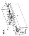
- Fig. 1 shows an oblique perspective view of a bending machine 1 for bending a rod and tubular workpiece 2 withdrawn endlessly from the coil.
- the bending machine 1 has a machine frame 3, which is provided on its upper side with a straightening unit 4 and with a rotatable feeder 5.
- the workpiece 2 drawn endlessly from the coil is removed from the rear side of the bending machine 1 (in FIG Fig. 1 : From the right) initially supplied to the straightening unit 4, passes through this in the rotatable feeder 5, from which it exits the front and then fed to the front side of the bending machine 1 a bending head 6 with a rotatable bending disc 7 for carrying out the desired bends.
- the bending disk 7 represents a bending template which can be rotated in both directions of rotation about a rotation axis 8 lying in a vertical direction and perpendicular to the longitudinal axis of the workpiece 2.
- this is provided with a shaping groove 9, in which the workpiece 2 tangentially enters upon reaching the bending disc 7 and remains during the bending operation.
- a bending finger 10 is further attached, which cooperates with the bending disc 7 for performing the bending operation and with this about the rotation axis 8 together (or independently) is pivotable.
- the workpiece 2 is arranged, which is bent upon rotation of the bending finger 10 and bending disc 7 around the circumference of the latter according to the circular shape formed by this.
- the bending head 6 can be moved, as shown by the arrows A and B, both in the vertical and in the transverse direction (that is, perpendicularly to the longitudinal axis of the workpiece 2).
- the bending head 6 is preferably of a construction as shown in the EP 1 591 174 B1 , z. B. Fig. 13, shown in detail.
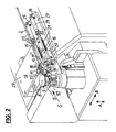
- Fig. 2 shows, the workpiece 2 passes before reaching the bending head 6 through a support jaw assembly therethrough.
- This consists of two support jaws 11, 12, which are arranged on both sides of the workpiece 2 and each of which is mounted on a bracket 13 and 14, which in turn is mounted on a support bar 15 and 16 via screws 17.
- the screws 17 extend through slots in a respective laterally projecting support flange of the holder 13 and 14, whereby the possibility exists, the respective holder 13 and 14 in their attachment to the corresponding support bar 15 and 16 relative to this and in one direction Spend perpendicular to the longitudinal axis of the workpiece 2 in a desired position and to fix in this.
- each support jaws 11, 12 is mounted on its associated bracket 13 and 14 by means of screws 18, wherein a device not shown in the figures is provided, by means of which each support jaws 11, 12 in turn also in the direction perpendicular to the workpiece 2 back in Its location can be fine tuned.
- the screws 18 each z. B. also in slightly elongated mounting holes of the associated support flange to allow a fine adjustment of the respective support jaw 11, 12 relative to the workpiece 2.
- a device for adjusting the height of the support jaws 11, 12 is provided, which in the Fig. 1 and 2 but not shown.
- Each support bar 15, 16 is seated on an associated guide block 19 or 20 and is slidably mounted on this in each case via a guide rail 21 in the longitudinal direction of the workpiece 2, wherein the guide rail 21 is mounted on the underside of the support bar 15 and 16 and in a corresponding Dovetail groove in the associated guide block 19 and 20 engages, so that a total of one dovetail guide is present.
- Each support bar 15, 16 is connected at its side facing away from the bending head 6 via a push rod 22 with a drive device in the form of a pneumatic adjusting cylinder 23, 24, which in turn about a pivot axis perpendicular to the longitudinal axis of the workpiece 2 and transverse to a support flange 25 and 26 is articulated.
- the pneumatic cylinders 23, 24 are, not shown in the figures, connected in a suitable manner to a central control device, by means of which they z. B. can be controlled by a program control.
- the guide blocks 19 and 20 are, like the support flanges 25, 26 for the pneumatic cylinder 23, 24 mounted on a base plate 27, whereby the whole support jaw assembly together with its drive with this base plate 27 forms a self-contained unit, in a suitable manner on the frame. 3 the bending machine 1 can be attached, such as from the Fig. 1 and 2 removable.
- the support bars 15 and 16, their respective push rod 22 and the associated pneumatic cylinder 23, 24 each extend in a direction parallel to the longitudinal direction of the workpiece 2 alignment, wherein by the pneumatic cylinder 23 and 24, the support bars 15 and 16 with the respective holders attached to them 13 and 14 and the respective support jaws 11, 12 in a direction parallel to the longitudinal axis of the workpiece 2 from a retracted starting position, as shown in FIGS Fig.
- each support jaws 11, 12 Removable while each support jaws 11, 12 is removed from the bending disc 7, be transferred to an extended end position, in which the extended support jaws 11 and 12 with its bending head 6 facing front to the point of the tangential inlet of the workpiece 2 in the Formnut 9 of the bending disc 7 is advanced and thereby lies directly next to the bending finger 10 of the bending head 6.
- the workpiece 2 engaging between the two in the forming groove 9 of the bending disk 7 is provided with the desired bend around the bending disk 7, the workpiece 2 being continuously fed in a region between the position its tangential inlet into the forming groove 9 and, seen in the transport direction of the workpiece 2, lying in front of this inlet point (according to the length of the respective support jaw 11 and 12 in the longitudinal direction of the workpiece 2 seen) from the support jaws 11 and 12 in the attached there Formnut 28 is supported.
- This support prevents just in the area immediately before the inlet of the workpiece 2 in the forming groove 9, the occurrence of cracks, faults o. ⁇ . On the workpiece 2, which would otherwise occur due to the bending forces occurring during the bending process.
- the arrangements each consisting of a support jaws 11 and 12, the associated bracket 13 and 14, the respective support bar 15 and 16, the associated guide block 19 and 20, the respective push rod 22 and the connected pneumatic cylinder 23 and 24 respectively , are mounted on the frame 3 of the bending machine 1, that each of them is located on one side of the workpiece 2, both arrangements, as seen relative to the workpiece 2, are mounted in their retracted initial position symmetrical to each other.
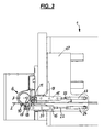
- Fig. 3 now shows a top view of the in Fig. 2 shown portion of the bending machine 1, wherein from this illustration, the arrangement of the support jaws 11 and 12 with the supporting elements 13 and 14, 15 and 16, and the respective push rods 22 and the respectively associated pneumatic cylinder 23 and 24 on both sides of the workpiece. 2 is apparent.
- FIG. 3 shows the case of a right bend, which in the position in Fig. 3 has not yet begun, which is why the workpiece 2 still protrudes beyond the bending head 6 and is bent only by a subsequent movement of the bending finger 10 and the bending disc 7.
- the support jaws 12 has been spent on the pneumatic cylinder 24 in its extended end position, in which he how Figure 3 shows, is arranged directly beside the bending finger 10 and spent with its front end portion up to the point of the tangential inlet of the workpiece 2 in the guide groove 9 of the bending disc 7. From here, the support jaw 12 supports the workpiece 2 on its opposite side of the bending disc 7 over a longitudinal section away, which lies in front of the tangential inlet point and the length of the support jaw 12 (seen in the longitudinal direction of the workpiece 2).
- Fig. 3 shows, the other holding jaws 11 is spent on the him driving the pneumatic cylinder 23 in its retracted position, in which he also abuts on the other side against the workpiece 2, but the same from the bending head 6 and the bending disc 7 is removed.
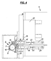
- Fig. 4 now shows the same section of the bending machine 1, as in Fig. 3 is shown, but here in the case of left turn.
- Fig. 4 how out Fig. 4 compared to Fig. 3 can be taken is in Fig. 4 the bending head 6 with the bracket supporting him side of the workpiece 2 so that the workpiece 2 now on the compared to Fig. 3 opposite side of the bending disc 7 is located. If a change from right to left bending or vice versa during the treatment of the workpiece 2 are made, to this change in position of the bending head 6, however, not only its lateral process in the direction of travel B (see. Fig. 1 and Fig. 2 ), but also a lowering of the bending head 6 in the direction A (see. Fig. 1 and Fig. 2 ) to perform under the workpiece 2, the lateral movement in the direction B and then brought back up to the desired height position.
- the support jaws 11 and 12 can perform different functions in the order shown:
Landscapes
- Engineering & Computer Science (AREA)
- Mechanical Engineering (AREA)
- Bending Of Plates, Rods, And Pipes (AREA)
Priority Applications (5)
| Application Number | Priority Date | Filing Date | Title |
|---|---|---|---|
| EP08018255A EP2177287B1 (fr) | 2008-10-17 | 2008-10-17 | Agencement de joues de support destiné au support latéral de coulissement de pièces usinées en forme de tiges ou de tubes sur des cintreuses |
| AT08018255T ATE535323T1 (de) | 2008-10-17 | 2008-10-17 | Stützbackenanordnung zum gleitenden seitlichen abstützen von stab- und rohrförmigen werkstücken an biegemaschinen |
| JP2009226826A JP5114464B2 (ja) | 2008-10-17 | 2009-09-30 | 曲げ加工機におけるロッド形状及び管状ワークの摺動横方向支持用支持ジョー構造 |
| US12/579,990 US8359896B2 (en) | 2008-10-17 | 2009-10-15 | Support jaw arrangement for sliding lateral support of rod-shaped and tubular workpieces in bending machines |
| CN2009101797918A CN101722220B (zh) | 2008-10-17 | 2009-10-19 | 在弯曲机中滑动侧向支撑杆形管状工件的支撑爪装置 |
Applications Claiming Priority (1)
| Application Number | Priority Date | Filing Date | Title |
|---|---|---|---|
| EP08018255A EP2177287B1 (fr) | 2008-10-17 | 2008-10-17 | Agencement de joues de support destiné au support latéral de coulissement de pièces usinées en forme de tiges ou de tubes sur des cintreuses |
Publications (3)
| Publication Number | Publication Date |
|---|---|
| EP2177287A2 true EP2177287A2 (fr) | 2010-04-21 |
| EP2177287A3 EP2177287A3 (fr) | 2011-05-11 |
| EP2177287B1 EP2177287B1 (fr) | 2011-11-30 |
Family
ID=41507850
Family Applications (1)
| Application Number | Title | Priority Date | Filing Date |
|---|---|---|---|
| EP08018255A Active EP2177287B1 (fr) | 2008-10-17 | 2008-10-17 | Agencement de joues de support destiné au support latéral de coulissement de pièces usinées en forme de tiges ou de tubes sur des cintreuses |
Country Status (5)
| Country | Link |
|---|---|
| US (1) | US8359896B2 (fr) |
| EP (1) | EP2177287B1 (fr) |
| JP (1) | JP5114464B2 (fr) |
| CN (1) | CN101722220B (fr) |
| AT (1) | ATE535323T1 (fr) |
Cited By (5)
| Publication number | Priority date | Publication date | Assignee | Title |
|---|---|---|---|---|
| CN102151730A (zh) * | 2010-12-09 | 2011-08-17 | 中山市奥美森工业有限公司 | 长u弯管机的折弯装置的位置切换部件 |
| CN103706724A (zh) * | 2013-12-20 | 2014-04-09 | 南京迈欧机械制造有限公司 | 一种可伸缩直管自动形成装置 |
| DE102017117979A1 (de) | 2017-08-08 | 2019-02-14 | Wafios Aktiengesellschaft | Biegemaschine zum Biegen von stab- oder rohrförmigen Werkstücken |
| CN112091022A (zh) * | 2020-09-15 | 2020-12-18 | 戚晓芳 | 一种石油管道弯管用辅助机构 |
| CN119387374A (zh) * | 2024-11-07 | 2025-02-07 | 珠海格力智能装备有限公司 | 一种弯套一体机的弯u定位装置及其工作方法 |
Families Citing this family (15)
| Publication number | Priority date | Publication date | Assignee | Title |
|---|---|---|---|---|
| CN101966548A (zh) * | 2010-11-03 | 2011-02-09 | 天津市建科机械制造有限公司 | 具有夹紧步进机构的钢筋自动弯曲机 |
| CN102009108A (zh) * | 2010-11-17 | 2011-04-13 | 天津市建科机械制造有限公司 | 钢筋自动弯箍机上的夹紧回送弯曲机构 |
| ITUD20110061A1 (it) * | 2011-04-18 | 2012-10-19 | Piegatrici Macch Elettr | Macchina piegatrice di barre metalliche, quali tondi per armatura o simili |
| TWI424893B (zh) * | 2011-06-15 | 2014-02-01 | Chiao Sheng Machinery Co Ltd | 條狀物彎曲成形加工機 |
| DE102012102057A1 (de) * | 2012-03-12 | 2013-09-12 | Elcede Gmbh | Biegeeinheit |
| CN102716952A (zh) * | 2012-06-28 | 2012-10-10 | 常熟市电力机具有限公司 | 弯管机 |
| ITMI20131272A1 (it) * | 2013-07-29 | 2015-01-30 | Crippa Spa | Macchina per curvare tubi con calandra posteriore e relativo procedimento di calandratura. |
| CN105013884A (zh) * | 2015-08-20 | 2015-11-04 | 江苏一机机械科技有限公司 | 高精度液压折弯机 |
| ITUB20153259A1 (it) * | 2015-08-27 | 2017-02-27 | M E P Macch Elettroniche Piegatrici Spa | Macchina combinata per lavorare vergelle e relativo procedimento di lavorazione |
| EP3238850B1 (fr) * | 2016-04-27 | 2019-10-23 | Advanced Orthodontic Solutions | Machine de pliage de fil |
| CN108461440B (zh) * | 2018-03-30 | 2024-04-05 | 上海新创达半导体设备技术有限公司 | 一种晶圆对中装置及方法 |
| US11351587B2 (en) | 2020-03-31 | 2022-06-07 | Hsin-Po Huang | Single bending device for continuous three-dimensional bending |
| CN111872689A (zh) * | 2020-07-07 | 2020-11-03 | 上海友升铝业有限公司 | 双边拉伸式拉弯设备及其拉弯方法 |
| CN116571647A (zh) * | 2023-05-26 | 2023-08-11 | 奥美森智能装备股份有限公司 | 一种超长扁管弯管机的上料机构 |
| CN119387405B (zh) * | 2024-12-30 | 2025-04-15 | 温州创睿五金模具有限公司 | 模内多孔侧冲机构 |
Citations (8)
| Publication number | Priority date | Publication date | Assignee | Title |
|---|---|---|---|---|
| US4959984A (en) | 1989-08-17 | 1990-10-02 | Ap Parts Manufacturing Company | Precision bending apparatus |
| DE3922326C2 (fr) | 1989-05-11 | 1992-11-19 | Chuo Electric Mfg. Co., Ltd., Seto, Aichi, Jp | |
| EP0649687B1 (fr) | 1993-10-21 | 1999-01-07 | Rigobert Dipl.-Ing. Schwarze | Machine à cintrer les tubes |
| DE20118444U1 (de) | 2001-11-14 | 2002-02-21 | Sendrowski, Günter, Dipl.-Ing., 57271 Hilchenbach | Faltenglätter |
| WO2004000479A1 (fr) | 2002-06-25 | 2003-12-31 | Silfax | Support de reglette pour machine a cintrer |
| DE60100147T2 (de) | 2001-10-02 | 2004-01-29 | Macchine Curvatubi Crippa Agos | Vorrichtung und Verfahren zum Ziehbiegen |
| EP0934783B1 (fr) | 1998-02-03 | 2006-05-03 | Kabushiki Kaisha Opton | Dispositif de cintrage |
| EP1591174B1 (fr) | 2004-03-26 | 2008-05-28 | WAFIOS Aktiengesellschaft | Dispositif de pliage pour des pièces en forme de barre et de tube |
Family Cites Families (14)
| Publication number | Priority date | Publication date | Assignee | Title |
|---|---|---|---|---|
| DE2904885A1 (de) | 1979-02-09 | 1980-08-14 | Rothenberger Gmbh Co | Biegevorrichtung fuer metallrohre |
| IT1235340B (it) * | 1988-12-16 | 1992-06-30 | Frosinone | Macchina curvatubi portatile a comando elettromeccanico ed asservimento elettronico |
| DE4335901A1 (de) * | 1993-10-21 | 1995-04-27 | Schwarze Rigobert | Doppelkopf-Rohrbiegemaschine |
| FR2747328B1 (fr) * | 1996-04-10 | 1998-06-19 | Robolix Sa | Machine a cintrer ou a cambrer un profile, et tete de cintrage pour une telle machine |
| GB2325630A (en) * | 1997-05-30 | 1998-12-02 | Eurobend Ltd | Bending apparatus |
| JPH11138215A (ja) * | 1997-11-06 | 1999-05-25 | Yamamoto Suiatsu Kogyosho:Kk | パイプベンダー |
| JP2001096312A (ja) * | 1999-09-29 | 2001-04-10 | Calsonic Kansei Corp | ツインヘッド型パイプ曲げ装置 |
| US6434995B1 (en) * | 1999-10-15 | 2002-08-20 | Usui Kokusai Sangyo Kaisha Limited | Method of bending small diameter metal pipe and its apparatus |
| JP3413520B2 (ja) * | 1999-12-09 | 2003-06-03 | 矢崎化工株式会社 | 複合射出成形方法 |
| EP1270104B1 (fr) * | 2000-02-17 | 2009-11-04 | Sanoh Kogyo Kabushiki Kaisha | Machine a plier |
| US6644079B2 (en) * | 2001-12-21 | 2003-11-11 | Burr Oak Tool And Gauge Company, Inc. | Hairpin bender with leg length measurement and adjustment feature |
| US7021102B2 (en) * | 2003-03-15 | 2006-04-04 | Trumpf Rohrtechnik Gmbh + Co. Kg | Bending machine with bending tools on opposite sides of a tool platen |
| CN2652548Y (zh) * | 2003-10-31 | 2004-11-03 | 洛阳安力机械有限公司 | 双向反弯加芯全液压弯管机 |
| JP2008175259A (ja) * | 2007-01-17 | 2008-07-31 | Nsk Ltd | リニアガイド装置 |
-
2008
- 2008-10-17 EP EP08018255A patent/EP2177287B1/fr active Active
- 2008-10-17 AT AT08018255T patent/ATE535323T1/de active
-
2009
- 2009-09-30 JP JP2009226826A patent/JP5114464B2/ja not_active Expired - Fee Related
- 2009-10-15 US US12/579,990 patent/US8359896B2/en not_active Expired - Fee Related
- 2009-10-19 CN CN2009101797918A patent/CN101722220B/zh not_active Expired - Fee Related
Patent Citations (8)
| Publication number | Priority date | Publication date | Assignee | Title |
|---|---|---|---|---|
| DE3922326C2 (fr) | 1989-05-11 | 1992-11-19 | Chuo Electric Mfg. Co., Ltd., Seto, Aichi, Jp | |
| US4959984A (en) | 1989-08-17 | 1990-10-02 | Ap Parts Manufacturing Company | Precision bending apparatus |
| EP0649687B1 (fr) | 1993-10-21 | 1999-01-07 | Rigobert Dipl.-Ing. Schwarze | Machine à cintrer les tubes |
| EP0934783B1 (fr) | 1998-02-03 | 2006-05-03 | Kabushiki Kaisha Opton | Dispositif de cintrage |
| DE60100147T2 (de) | 2001-10-02 | 2004-01-29 | Macchine Curvatubi Crippa Agos | Vorrichtung und Verfahren zum Ziehbiegen |
| DE20118444U1 (de) | 2001-11-14 | 2002-02-21 | Sendrowski, Günter, Dipl.-Ing., 57271 Hilchenbach | Faltenglätter |
| WO2004000479A1 (fr) | 2002-06-25 | 2003-12-31 | Silfax | Support de reglette pour machine a cintrer |
| EP1591174B1 (fr) | 2004-03-26 | 2008-05-28 | WAFIOS Aktiengesellschaft | Dispositif de pliage pour des pièces en forme de barre et de tube |
Cited By (11)
| Publication number | Priority date | Publication date | Assignee | Title |
|---|---|---|---|---|
| CN102151730A (zh) * | 2010-12-09 | 2011-08-17 | 中山市奥美森工业有限公司 | 长u弯管机的折弯装置的位置切换部件 |
| CN102151730B (zh) * | 2010-12-09 | 2013-01-30 | 中山市奥美森工业有限公司 | 长u弯管机的折弯装置的位置切换部件 |
| CN103706724A (zh) * | 2013-12-20 | 2014-04-09 | 南京迈欧机械制造有限公司 | 一种可伸缩直管自动形成装置 |
| CN103706724B (zh) * | 2013-12-20 | 2015-09-30 | 南京迈欧机械制造有限公司 | 一种可伸缩直管自动形成装置 |
| DE102017117979A1 (de) | 2017-08-08 | 2019-02-14 | Wafios Aktiengesellschaft | Biegemaschine zum Biegen von stab- oder rohrförmigen Werkstücken |
| WO2019029893A1 (fr) | 2017-08-08 | 2019-02-14 | Wafios Aktiengesellschaft | Machine à cintrer pour le cintrage de pièces en forme de tige ou de tube |
| JP2020529324A (ja) * | 2017-08-08 | 2020-10-08 | ヴァフィオス アクチェンゲゼルシャフトWAFIOS Aktiengesellschaft | ロッド状又は管状加工物を曲げる曲げ機械 |
| US11484928B2 (en) | 2017-08-08 | 2022-11-01 | Wafios Aktiengesellschaft | Bending machine for bending rod-shaped or tubular workpieces |
| CN112091022A (zh) * | 2020-09-15 | 2020-12-18 | 戚晓芳 | 一种石油管道弯管用辅助机构 |
| CN112091022B (zh) * | 2020-09-15 | 2024-01-05 | 戚晓芳 | 一种石油管道弯管用辅助机构 |
| CN119387374A (zh) * | 2024-11-07 | 2025-02-07 | 珠海格力智能装备有限公司 | 一种弯套一体机的弯u定位装置及其工作方法 |
Also Published As
| Publication number | Publication date |
|---|---|
| EP2177287B1 (fr) | 2011-11-30 |
| JP2010094736A (ja) | 2010-04-30 |
| JP5114464B2 (ja) | 2013-01-09 |
| EP2177287A3 (fr) | 2011-05-11 |
| US8359896B2 (en) | 2013-01-29 |
| US20100095732A1 (en) | 2010-04-22 |
| CN101722220A (zh) | 2010-06-09 |
| CN101722220B (zh) | 2012-10-24 |
| ATE535323T1 (de) | 2011-12-15 |
Similar Documents
| Publication | Publication Date | Title |
|---|---|---|
| EP2177287B1 (fr) | Agencement de joues de support destiné au support latéral de coulissement de pièces usinées en forme de tiges ou de tubes sur des cintreuses | |
| EP1591174B1 (fr) | Dispositif de pliage pour des pièces en forme de barre et de tube | |
| EP2697008B1 (fr) | Procédé et machine de production de ressorts | |
| EP1849536B1 (fr) | Machine de cintrage pour des pièces en forme de barre, telle que du fil ou du tube | |
| EP1700647B1 (fr) | Dispositif de cintrage pour les pièces en forme de tube et de barre et dispositif de lissage de pli | |
| DE3327509A1 (de) | Biegevorrichtung | |
| DE102011015570A1 (de) | Biegekopf zum Biegen stab- und rohrförmiger Werkstücke | |
| DE2455702A1 (de) | Verfahren und vorrichtung zur besseren zugaenglichmachung des werkzeugraumes einer formmaschine | |
| EP2543452A1 (fr) | Dispositif de pliage pour pièces usinées en forme de tige | |
| CH652947A5 (de) | Drahtbiegemaschine. | |
| DE69202679T2 (de) | Biege-Schermaschine mit mehreren Arbeitsebenen. | |
| AT401360B (de) | Biegeanlage für stäbe | |
| EP0701878A1 (fr) | Dispositif et procédé de fabrication de tuyaux | |
| DE2741576A1 (de) | Bearbeitungsmaschine fuer draht und band, insbesondere stanz- und biegeautomat, mit mehreren werkzeugebenen | |
| EP3664945B1 (fr) | Machine à cintrer pour le cintrage de pièces en forme de tige ou de tube | |
| DE2918813A1 (de) | Vorrichtung zum biegen von metallstaeben | |
| EP2255903B1 (fr) | Dispositif de refoulement de tête | |
| DE102009024406B4 (de) | Rotationsbiegewerkzeug mit Exzenterklemmung | |
| DE102010013688B4 (de) | Biegevorrichtung für längliche Werkstücke | |
| DE102011014953B4 (de) | Biegevorrichtung für stab- und rohrförmige Werkstücke | |
| EP1380362B1 (fr) | Machine de cintrage de tubes avec alimentation de tubes et recul de mandrin | |
| DE102013200851B4 (de) | Biegevorrichtung für strangförmige Werkstücke | |
| EP3551356B1 (fr) | Installation de fabrication dotée d'un outil de serrage ainsi que procédé de réglage d'une longueur totale d'un bord de pliage de l'outil de serrage | |
| DE2843531C2 (de) | Maschine zum Herstellen von gitterträgerartigen Bewehrungsgebilden für Stahlbeton | |
| EP3456443A1 (fr) | Dispositif d'alimentation en matériau en barres |
Legal Events
| Date | Code | Title | Description |
|---|---|---|---|
| PUAI | Public reference made under article 153(3) epc to a published international application that has entered the european phase |
Free format text: ORIGINAL CODE: 0009012 |
|
| AK | Designated contracting states |
Kind code of ref document: A2 Designated state(s): AT BE BG CH CY CZ DE DK EE ES FI FR GB GR HR HU IE IS IT LI LT LU LV MC MT NL NO PL PT RO SE SI SK TR |
|
| AX | Request for extension of the european patent |
Extension state: AL BA MK RS |
|
| PUAL | Search report despatched |
Free format text: ORIGINAL CODE: 0009013 |
|
| AK | Designated contracting states |
Kind code of ref document: A3 Designated state(s): AT BE BG CH CY CZ DE DK EE ES FI FR GB GR HR HU IE IS IT LI LT LU LV MC MT NL NO PL PT RO SE SI SK TR |
|
| AX | Request for extension of the european patent |
Extension state: AL BA MK RS |
|
| RIC1 | Information provided on ipc code assigned before grant |
Ipc: B21D 7/02 20060101AFI20100217BHEP Ipc: B21D 7/024 20060101ALI20110405BHEP Ipc: B21D 7/022 20060101ALI20110405BHEP Ipc: B21D 7/04 20060101ALI20110405BHEP Ipc: B21D 11/12 20060101ALI20110405BHEP |
|
| 17P | Request for examination filed |
Effective date: 20110504 |
|
| GRAP | Despatch of communication of intention to grant a patent |
Free format text: ORIGINAL CODE: EPIDOSNIGR1 |
|
| RIC1 | Information provided on ipc code assigned before grant |
Ipc: B21D 11/12 20060101ALI20110615BHEP Ipc: B21D 7/02 20060101AFI20110615BHEP Ipc: B21D 7/04 20060101ALI20110615BHEP Ipc: B21D 7/024 20060101ALI20110615BHEP Ipc: B21D 7/022 20060101ALI20110615BHEP |
|
| GRAS | Grant fee paid |
Free format text: ORIGINAL CODE: EPIDOSNIGR3 |
|
| GRAA | (expected) grant |
Free format text: ORIGINAL CODE: 0009210 |
|
| AK | Designated contracting states |
Kind code of ref document: B1 Designated state(s): AT BE BG CH CY CZ DE DK EE ES FI FR GB GR HR HU IE IS IT LI LT LU LV MC MT NL NO PL PT RO SE SI SK TR |
|
| REG | Reference to a national code |
Ref country code: GB Ref legal event code: FG4D Free format text: NOT ENGLISH Ref country code: CH Ref legal event code: EP |
|
| REG | Reference to a national code |
Ref country code: IE Ref legal event code: FG4D Free format text: LANGUAGE OF EP DOCUMENT: GERMAN |
|
| AKX | Designation fees paid |
Designated state(s): AT BE BG CH CY CZ DE DK EE ES FI FR GB GR HR HU IE IS IT LI LT LU LV MC MT NL NO PL PT RO SE SI SK TR |
|
| REG | Reference to a national code |
Ref country code: DE Ref legal event code: R096 Ref document number: 502008005722 Country of ref document: DE Effective date: 20120216 |
|
| REG | Reference to a national code |
Ref country code: NL Ref legal event code: VDEP Effective date: 20111130 |
|
| LTIE | Lt: invalidation of european patent or patent extension |
Effective date: 20111130 |
|
| PG25 | Lapsed in a contracting state [announced via postgrant information from national office to epo] |
Ref country code: LT Free format text: LAPSE BECAUSE OF FAILURE TO SUBMIT A TRANSLATION OF THE DESCRIPTION OR TO PAY THE FEE WITHIN THE PRESCRIBED TIME-LIMIT Effective date: 20111130 Ref country code: NO Free format text: LAPSE BECAUSE OF FAILURE TO SUBMIT A TRANSLATION OF THE DESCRIPTION OR TO PAY THE FEE WITHIN THE PRESCRIBED TIME-LIMIT Effective date: 20120229 Ref country code: IS Free format text: LAPSE BECAUSE OF FAILURE TO SUBMIT A TRANSLATION OF THE DESCRIPTION OR TO PAY THE FEE WITHIN THE PRESCRIBED TIME-LIMIT Effective date: 20120330 |
|
| PG25 | Lapsed in a contracting state [announced via postgrant information from national office to epo] |
Ref country code: SE Free format text: LAPSE BECAUSE OF FAILURE TO SUBMIT A TRANSLATION OF THE DESCRIPTION OR TO PAY THE FEE WITHIN THE PRESCRIBED TIME-LIMIT Effective date: 20111130 Ref country code: LV Free format text: LAPSE BECAUSE OF FAILURE TO SUBMIT A TRANSLATION OF THE DESCRIPTION OR TO PAY THE FEE WITHIN THE PRESCRIBED TIME-LIMIT Effective date: 20111130 Ref country code: PT Free format text: LAPSE BECAUSE OF FAILURE TO SUBMIT A TRANSLATION OF THE DESCRIPTION OR TO PAY THE FEE WITHIN THE PRESCRIBED TIME-LIMIT Effective date: 20120330 Ref country code: GR Free format text: LAPSE BECAUSE OF FAILURE TO SUBMIT A TRANSLATION OF THE DESCRIPTION OR TO PAY THE FEE WITHIN THE PRESCRIBED TIME-LIMIT Effective date: 20120301 Ref country code: HR Free format text: LAPSE BECAUSE OF FAILURE TO SUBMIT A TRANSLATION OF THE DESCRIPTION OR TO PAY THE FEE WITHIN THE PRESCRIBED TIME-LIMIT Effective date: 20111130 Ref country code: SI Free format text: LAPSE BECAUSE OF FAILURE TO SUBMIT A TRANSLATION OF THE DESCRIPTION OR TO PAY THE FEE WITHIN THE PRESCRIBED TIME-LIMIT Effective date: 20111130 Ref country code: NL Free format text: LAPSE BECAUSE OF FAILURE TO SUBMIT A TRANSLATION OF THE DESCRIPTION OR TO PAY THE FEE WITHIN THE PRESCRIBED TIME-LIMIT Effective date: 20111130 |
|
| REG | Reference to a national code |
Ref country code: IE Ref legal event code: FD4D |
|
| PG25 | Lapsed in a contracting state [announced via postgrant information from national office to epo] |
Ref country code: CY Free format text: LAPSE BECAUSE OF FAILURE TO SUBMIT A TRANSLATION OF THE DESCRIPTION OR TO PAY THE FEE WITHIN THE PRESCRIBED TIME-LIMIT Effective date: 20111130 |
|
| PG25 | Lapsed in a contracting state [announced via postgrant information from national office to epo] |
Ref country code: EE Free format text: LAPSE BECAUSE OF FAILURE TO SUBMIT A TRANSLATION OF THE DESCRIPTION OR TO PAY THE FEE WITHIN THE PRESCRIBED TIME-LIMIT Effective date: 20111130 Ref country code: CZ Free format text: LAPSE BECAUSE OF FAILURE TO SUBMIT A TRANSLATION OF THE DESCRIPTION OR TO PAY THE FEE WITHIN THE PRESCRIBED TIME-LIMIT Effective date: 20111130 Ref country code: DK Free format text: LAPSE BECAUSE OF FAILURE TO SUBMIT A TRANSLATION OF THE DESCRIPTION OR TO PAY THE FEE WITHIN THE PRESCRIBED TIME-LIMIT Effective date: 20111130 Ref country code: BG Free format text: LAPSE BECAUSE OF FAILURE TO SUBMIT A TRANSLATION OF THE DESCRIPTION OR TO PAY THE FEE WITHIN THE PRESCRIBED TIME-LIMIT Effective date: 20120229 Ref country code: IE Free format text: LAPSE BECAUSE OF FAILURE TO SUBMIT A TRANSLATION OF THE DESCRIPTION OR TO PAY THE FEE WITHIN THE PRESCRIBED TIME-LIMIT Effective date: 20111130 Ref country code: SK Free format text: LAPSE BECAUSE OF FAILURE TO SUBMIT A TRANSLATION OF THE DESCRIPTION OR TO PAY THE FEE WITHIN THE PRESCRIBED TIME-LIMIT Effective date: 20111130 |
|
| PG25 | Lapsed in a contracting state [announced via postgrant information from national office to epo] |
Ref country code: RO Free format text: LAPSE BECAUSE OF FAILURE TO SUBMIT A TRANSLATION OF THE DESCRIPTION OR TO PAY THE FEE WITHIN THE PRESCRIBED TIME-LIMIT Effective date: 20111130 Ref country code: PL Free format text: LAPSE BECAUSE OF FAILURE TO SUBMIT A TRANSLATION OF THE DESCRIPTION OR TO PAY THE FEE WITHIN THE PRESCRIBED TIME-LIMIT Effective date: 20111130 |
|
| PLBE | No opposition filed within time limit |
Free format text: ORIGINAL CODE: 0009261 |
|
| STAA | Information on the status of an ep patent application or granted ep patent |
Free format text: STATUS: NO OPPOSITION FILED WITHIN TIME LIMIT |
|
| 26N | No opposition filed |
Effective date: 20120831 |
|
| REG | Reference to a national code |
Ref country code: DE Ref legal event code: R097 Ref document number: 502008005722 Country of ref document: DE Effective date: 20120831 |
|
| BERE | Be: lapsed |
Owner name: WAFIOS A.G. Effective date: 20121031 |
|
| PG25 | Lapsed in a contracting state [announced via postgrant information from national office to epo] |
Ref country code: ES Free format text: LAPSE BECAUSE OF FAILURE TO SUBMIT A TRANSLATION OF THE DESCRIPTION OR TO PAY THE FEE WITHIN THE PRESCRIBED TIME-LIMIT Effective date: 20120311 |
|
| PG25 | Lapsed in a contracting state [announced via postgrant information from national office to epo] |
Ref country code: MC Free format text: LAPSE BECAUSE OF NON-PAYMENT OF DUE FEES Effective date: 20121031 |
|
| REG | Reference to a national code |
Ref country code: CH Ref legal event code: PL |
|
| GBPC | Gb: european patent ceased through non-payment of renewal fee |
Effective date: 20121017 |
|
| PG25 | Lapsed in a contracting state [announced via postgrant information from national office to epo] |
Ref country code: FI Free format text: LAPSE BECAUSE OF FAILURE TO SUBMIT A TRANSLATION OF THE DESCRIPTION OR TO PAY THE FEE WITHIN THE PRESCRIBED TIME-LIMIT Effective date: 20111130 |
|
| PG25 | Lapsed in a contracting state [announced via postgrant information from national office to epo] |
Ref country code: CH Free format text: LAPSE BECAUSE OF NON-PAYMENT OF DUE FEES Effective date: 20121031 Ref country code: LI Free format text: LAPSE BECAUSE OF NON-PAYMENT OF DUE FEES Effective date: 20121031 Ref country code: BE Free format text: LAPSE BECAUSE OF NON-PAYMENT OF DUE FEES Effective date: 20121031 Ref country code: GB Free format text: LAPSE BECAUSE OF NON-PAYMENT OF DUE FEES Effective date: 20121017 |
|
| PG25 | Lapsed in a contracting state [announced via postgrant information from national office to epo] |
Ref country code: MT Free format text: LAPSE BECAUSE OF FAILURE TO SUBMIT A TRANSLATION OF THE DESCRIPTION OR TO PAY THE FEE WITHIN THE PRESCRIBED TIME-LIMIT Effective date: 20111130 |
|
| PG25 | Lapsed in a contracting state [announced via postgrant information from national office to epo] |
Ref country code: TR Free format text: LAPSE BECAUSE OF FAILURE TO SUBMIT A TRANSLATION OF THE DESCRIPTION OR TO PAY THE FEE WITHIN THE PRESCRIBED TIME-LIMIT Effective date: 20111130 |
|
| PG25 | Lapsed in a contracting state [announced via postgrant information from national office to epo] |
Ref country code: LU Free format text: LAPSE BECAUSE OF NON-PAYMENT OF DUE FEES Effective date: 20121017 |
|
| PG25 | Lapsed in a contracting state [announced via postgrant information from national office to epo] |
Ref country code: HU Free format text: LAPSE BECAUSE OF FAILURE TO SUBMIT A TRANSLATION OF THE DESCRIPTION OR TO PAY THE FEE WITHIN THE PRESCRIBED TIME-LIMIT Effective date: 20081017 |
|
| REG | Reference to a national code |
Ref country code: AT Ref legal event code: MM01 Ref document number: 535323 Country of ref document: AT Kind code of ref document: T Effective date: 20131017 |
|
| PG25 | Lapsed in a contracting state [announced via postgrant information from national office to epo] |
Ref country code: AT Free format text: LAPSE BECAUSE OF NON-PAYMENT OF DUE FEES Effective date: 20131017 |
|
| REG | Reference to a national code |
Ref country code: FR Ref legal event code: PLFP Year of fee payment: 8 |
|
| REG | Reference to a national code |
Ref country code: FR Ref legal event code: PLFP Year of fee payment: 9 |
|
| REG | Reference to a national code |
Ref country code: FR Ref legal event code: PLFP Year of fee payment: 10 |
|
| REG | Reference to a national code |
Ref country code: FR Ref legal event code: PLFP Year of fee payment: 11 |
|
| PGFP | Annual fee paid to national office [announced via postgrant information from national office to epo] |
Ref country code: IT Payment date: 20211029 Year of fee payment: 14 Ref country code: FR Payment date: 20211022 Year of fee payment: 14 |
|
| PG25 | Lapsed in a contracting state [announced via postgrant information from national office to epo] |
Ref country code: FR Free format text: LAPSE BECAUSE OF NON-PAYMENT OF DUE FEES Effective date: 20221031 |
|
| PG25 | Lapsed in a contracting state [announced via postgrant information from national office to epo] |
Ref country code: IT Free format text: LAPSE BECAUSE OF NON-PAYMENT OF DUE FEES Effective date: 20221017 |
|
| PGFP | Annual fee paid to national office [announced via postgrant information from national office to epo] |
Ref country code: DE Payment date: 20241022 Year of fee payment: 17 |