EP2177470A2 - Chariot de manutention destiné au transport de palettes spéciales - Google Patents
Chariot de manutention destiné au transport de palettes spéciales Download PDFInfo
- Publication number
- EP2177470A2 EP2177470A2 EP09013125A EP09013125A EP2177470A2 EP 2177470 A2 EP2177470 A2 EP 2177470A2 EP 09013125 A EP09013125 A EP 09013125A EP 09013125 A EP09013125 A EP 09013125A EP 2177470 A2 EP2177470 A2 EP 2177470A2
- Authority
- EP
- European Patent Office
- Prior art keywords
- truck according
- load
- drive
- truck
- arm
- Prior art date
- Legal status (The legal status is an assumption and is not a legal conclusion. Google has not performed a legal analysis and makes no representation as to the accuracy of the status listed.)
- Granted
Links
Images


Classifications
-
- B—PERFORMING OPERATIONS; TRANSPORTING
- B66—HOISTING; LIFTING; HAULING
- B66F—HOISTING, LIFTING, HAULING OR PUSHING, NOT OTHERWISE PROVIDED FOR, e.g. DEVICES WHICH APPLY A LIFTING OR PUSHING FORCE DIRECTLY TO THE SURFACE OF A LOAD
- B66F9/00—Devices for lifting or lowering bulky or heavy goods for loading or unloading purposes
- B66F9/06—Devices for lifting or lowering bulky or heavy goods for loading or unloading purposes movable, with their loads, on wheels or the like, e.g. fork-lift trucks
- B66F9/075—Constructional features or details
- B66F9/12—Platforms; Forks; Other load supporting or gripping members
-
- B—PERFORMING OPERATIONS; TRANSPORTING
- B66—HOISTING; LIFTING; HAULING
- B66F—HOISTING, LIFTING, HAULING OR PUSHING, NOT OTHERWISE PROVIDED FOR, e.g. DEVICES WHICH APPLY A LIFTING OR PUSHING FORCE DIRECTLY TO THE SURFACE OF A LOAD
- B66F9/00—Devices for lifting or lowering bulky or heavy goods for loading or unloading purposes
- B66F9/06—Devices for lifting or lowering bulky or heavy goods for loading or unloading purposes movable, with their loads, on wheels or the like, e.g. fork-lift trucks
- B66F9/075—Constructional features or details
- B66F9/08—Masts; Guides; Chains
-
- B—PERFORMING OPERATIONS; TRANSPORTING
- B66—HOISTING; LIFTING; HAULING
- B66F—HOISTING, LIFTING, HAULING OR PUSHING, NOT OTHERWISE PROVIDED FOR, e.g. DEVICES WHICH APPLY A LIFTING OR PUSHING FORCE DIRECTLY TO THE SURFACE OF A LOAD
- B66F9/00—Devices for lifting or lowering bulky or heavy goods for loading or unloading purposes
- B66F9/06—Devices for lifting or lowering bulky or heavy goods for loading or unloading purposes movable, with their loads, on wheels or the like, e.g. fork-lift trucks
- B66F9/075—Constructional features or details
- B66F9/08—Masts; Guides; Chains
- B66F9/087—Monomasts
Definitions
- the invention relates to an industrial truck for transporting special pallets according to claim 1.
- a standard pallet (Euro pallet) has a dimension of 800 x 1200 millimeters. There are also other sizes known.
- the pallets are transported and stacked mainly by industrial trucks, which are designed with forks or fork arms. The usual design allows only the transport of a pallet.
- loads are stacked and transported on smaller pallets, for example measuring one quarter of a Euro pallet.
- the goods are placed on the pallets, directly in the sales room.
- it has been accepted to make the smaller pallets so that they each occupy half, a third or a quarter of a standard pallet.
- standard trucks are used for storage on shelves and transport standard trucks.
- the smaller pallets are set up on standard pallets. At the retailer, the smaller pallets must then be taken down by the big ones and taken to the showroom.
- the invention has for its object to provide a truck for transporting special pallets that can quickly and safely stir stacking and transport operations with little space and without great physical effort.
- two parallel spaced mast profiles are laterally welded to the central arm, preferably via spacer blocks.
- the load arm back is guided in the mast profiles, preferably via rollers.
- a bearing component for a traction drive with a pivotable or steerable drive wheel is articulated via sprung arms to the mast profiles. The articulation is preferably at the back of the mast profiles.
- the truck according to the invention thus has a self-supporting construction, which is easy to manufacture and leads to a lightweight device.
- parallel spaced tabs are attached to the back of the Lastarmrückens for the storage of guide rollers.
- spaced two rubber spring element pairs are placed on a fixed to the mast profiles holding member, which are coupled via links with rubber spring elements on the bearing component of the traction drive.
- an element pair can also be replaced by a single element to obtain a parallel guide.
- Such rubber spring elements are known per se. They consist of an outer and an inner sleeve, for example in square shape with elastomeric between the sleeves Material is introduced. With the aid of such a spring arrangement, a certain Bodenan horr is generated for the drive wheel, which is variable according to a further embodiment of the invention characterized in that the attachment of the first spring elements in height can be selected at different locations.
- bearing plates are attached to these on both sides of the mast profiles, which store at the bottom of castors.
- the bearing plates may comprise connecting struts according to a further embodiment of the invention, which in turn may be welded to the Hubprofilen.
- the bearing plates also serve to support batteries, preferably lithium cells. Lithium cells require much less space with the same useful energy content in relation to conventional lead-acid batteries and are also lighter. They also have the advantage that they can be recharged in a shorter time than lead-acid batteries and in contrast to these are maintenance-free.
- above the lithium cells on the support plates further lithium cells are arranged, which are aligned with a lithium cell above the spring arrangement for the traction drive. To achieve a total voltage of about 24 volts, therefore, preferably seven of these cells are provided.
- the truck according to the invention also has a lifting device to move the load arm in height.
- a conventional hydraulic drive can be taken.
- a spindle drive is provided, the electric motor preferably parallel is arranged to the spindle and the spindle nut cooperates with the spindle, which is in operative connection with two parallel spaced further tabs on the back of Lastarmrückens.
- the spindle is preferably rotatably attached to the tabs and the motor drives the spindle nut.
- An electric spindle drive has the advantage that an "oil-free" vehicle is thereby obtained, which is advantageous in particular for use in the food sector.
- a direct drive is provided for the traction drive.
- a direct drive requires only a small space and is characterized by quiet operation. However, it can also be a drive with gear, preferably with also lying engine, are provided.
- the steering of the truck according to the invention can take place via a drawbar, whereby the vehicle is characterized as a pedestrian vehicle.
- the drawbar is mounted so that it can be swiveled by at least +/- 90 °.
- Their connection with a preferably vertical steering axle is preferably carried out above the drive and batteries.
- a standing platform can be connected to the vehicle, which can be folded if necessary.
- a steering transmitter of small dimensions can be mounted close to the handle, which steers the drive wheel via an electric steering.
- a load-holding element is articulated laterally on the load arm back, which can be applied laterally about an approximately vertical axis against a load received by the load arm.
- the load-retaining elements become after receiving the small pallet folded laterally to this, so that the drive part facing part of the small range and also the goods located thereon can be safely supported laterally to the direction of travel.
- Height and length of the load-holding elements are chosen so that they do not protrude in the rest position substantially over the outer contour of the vehicle.
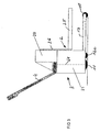
- Fig. 1-3 show a truck 1 with a load part 2 and a drive part 3 and a drawbar 4.
- the load part 2 has a middle load arm 25 with a rear Lastarmschreiben 26, which will be described later and is guided vertically adjustable in a mast.
- the drive member 3 has a central drive wheel 11 and laterally thereof two casters, one of which can be seen at 12.
- the drive member is also connected to a Radarm 13 which supports a load roller 10 at the free end.
- the truck shown for lifting and transporting small pallets 40 and 41 Like from the 4 and 5 shows, the truck shown for lifting and transporting small pallets 40 and 41.
- Fig. 5 It is shown how four small pallets are placed on a conventional large pallet 42, for example a Euro pallet.
- the wheel arm 13 can retract into the pallet 42, and the load arm 25 moves into the small pallet 40 and raises it, as in Fig. 5 shown. Subsequently, the truck 1 can drive out of the pallet 42 and transport the pallet 40 to a desired location.
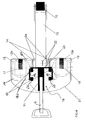
- a bearing member 23 is mounted vertically adjustable in the form of a plate on which rubber spring elements 20 are fixedly mounted on opposite sides of the longitudinal axis of the vehicle shown. Further rubber spring elements 60 are connected to a bearing plate, not shown, for a traction drive 19, not shown, of the industrial truck 1 shown. Between the rubber spring elements 20 and 60, links 62 are attached. In this way, a bias can be exerted on the drive bearing plate to press the drive wheel 11 with sufficient force against the ground.
- the bearing member 23, which is formed by a plate, is height-adjustable attached to the back of the mast sections 14 to change the bias.
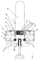
- Fig. 7 It can be seen that two lithium batteries 31, 32 each are arranged on the support plates 16. Above the lithium batteries 31, 32 further lithium batteries 33 are arranged in a row, namely one above the batteries on the support plate 16 and a lithium battery aligned above the traction drive 19. A charger, not shown, the lithium batteries can be assigned to the batteries without a Remove or without charging an external charger.
- Fig. 7 is located at 30 an electric lift motor standing, which adjusts the load arm back 26 in height via a spindle drive.
- the spindle is indicated, which cooperates with a spindle nut, not shown, and is secured to parallel spaced tabs 34 on the back of the Lastarmrückens 26.
- the spindle nut is connected to the hoist motor via a gearbox.
- the articulation of the drawbar 4 is disposed above a panel 21 of the truck 1.
- the dot-dash line 64 indicates the steering axis 64 for actuating the steerable drive wheel 11.
- the panel 21 surrounds in the lower area the drive not shown further and the lithium batteries 31 and 32.
- a panel 29 is shown, which surrounds a room for the accommodation of batteries 33, controls for the drives, a battery management system and other components of the electrical system of the truck shown 1. It also an on-board charger can be accommodated, so that only an electrical outlet is required for an intermediate charge.
- On the outer sides of the panels 21, 29 display and controls can be arranged.
- the drawbar 4 is arranged so that pivoting by at least +/- 90 ° to the lower portion of the upper panel 29 is possible.
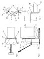
- load-holding elements 50, 51 are mounted pivotably about an axis 53 on the sides of the load-arm back 26.
- the load holders 50, 51 are shown at 52 in rest position. It can be seen that they are in the Essentially does not protrude beyond the outer contour of the vehicle. In the working position, the load holders 50, 51 are on the side of the pallet 40 and extend over a relatively large amount, beyond the fork back 26, to laterally support the load 66 resting on the pallet 40.
- Fig. 10 is an exemplary operation of the load-holding elements 50, 51 shown schematically.
- the load-holding elements 50, 51 which are elongated plate-shaped, arms 54, 55 are firmly connected.
- link arms 56, 57 are articulated, which in turn are articulated to a two-armed lever 58.
- the lever 58 is pivotable about a vertical axis 59.
- the pivot bearing is firmly connected to the Lastarmschreiben 26.
- FIG. 11 An alternative embodiment of load-retaining elements is in Fig. 11 indicated.
- An L-shaped load-holding element 63 is pivotally mounted about a vertical axis 61 on the load arm back 26. In the solid representation, the load-holding element 63 bears against the pallet 40. The rest position is shown in dashed lines. When adjusting the load-holding element 63 is to be pivoted by 180 °. It is therefore in the rest position on the outside of the panel 21 and 29 at. Again, it is only minimally on the outer contour of the vehicle over. In the load-holding element 63, a greater length of the load is secured than is the case with the load-holding elements 50, 51. The load holding elements 50, 51 and 63 are locked in their respective position in a suitable manner.
Landscapes
- Engineering & Computer Science (AREA)
- Transportation (AREA)
- Structural Engineering (AREA)
- Civil Engineering (AREA)
- Life Sciences & Earth Sciences (AREA)
- Geology (AREA)
- Mechanical Engineering (AREA)
- Forklifts And Lifting Vehicles (AREA)
- Handcart (AREA)
Applications Claiming Priority (1)
| Application Number | Priority Date | Filing Date | Title |
|---|---|---|---|
| DE200820013950 DE202008013950U1 (de) | 2008-10-18 | 2008-10-18 | Flurförderzeug zum Transport von Sonderplatten |
Publications (3)
| Publication Number | Publication Date |
|---|---|
| EP2177470A2 true EP2177470A2 (fr) | 2010-04-21 |
| EP2177470A3 EP2177470A3 (fr) | 2011-05-11 |
| EP2177470B1 EP2177470B1 (fr) | 2012-05-23 |
Family
ID=40340408
Family Applications (1)
| Application Number | Title | Priority Date | Filing Date |
|---|---|---|---|
| EP20090013125 Not-in-force EP2177470B1 (fr) | 2008-10-18 | 2009-10-16 | Chariot de manutention destiné au transport de palettes spéciales |
Country Status (2)
| Country | Link |
|---|---|
| EP (1) | EP2177470B1 (fr) |
| DE (1) | DE202008013950U1 (fr) |
Family Cites Families (4)
| Publication number | Priority date | Publication date | Assignee | Title |
|---|---|---|---|---|
| US2992749A (en) * | 1960-10-17 | 1961-07-18 | Themus A Spillios | Method of handling strip or bar materials |
| DE29514676U1 (de) * | 1995-09-13 | 1997-01-30 | Jungheinrich AG., 22047 Hamburg | Stapler |
| SE9801785L (sv) * | 1998-05-18 | 1999-11-19 | Bt Ind Ab | Anordning vid lastgaffel tillhörande en pallyftare, industritruck eller liknande |
| SE529749C2 (sv) * | 2004-11-06 | 2007-11-13 | Toyota Ind Sweden Ab | Truckmast |
-
2008
- 2008-10-18 DE DE200820013950 patent/DE202008013950U1/de not_active Expired - Lifetime
-
2009
- 2009-10-16 EP EP20090013125 patent/EP2177470B1/fr not_active Not-in-force
Also Published As
| Publication number | Publication date |
|---|---|
| EP2177470A3 (fr) | 2011-05-11 |
| DE202008013950U1 (de) | 2009-02-05 |
| DE202008013950U8 (de) | 2009-06-10 |
| EP2177470B1 (fr) | 2012-05-23 |
Similar Documents
| Publication | Publication Date | Title |
|---|---|---|
| EP0916615B1 (fr) | Véhicule sans conducteur, p. ex. véhicule de transport à navigation libre pour manipuler des charges | |
| DE102018112568A1 (de) | Flurförderzeug mit aus- und einfahrbarem Zusatzrad | |
| EP2570358A2 (fr) | Système de transport pour récipients de transport ou conteneurs à claire-voie | |
| WO2008031718A1 (fr) | Plate-forme pour porter et transporter des charges à fond roulant, et dispositif de transport équipé d'une telle plate-forme | |
| DE102018112566A1 (de) | Flurförderzeug mit ausfahrbarer Struktur | |
| EP3730450A1 (fr) | Chariot à levée initiale | |
| DE4126728C2 (de) | Hebe- und Förderfahrzeug | |
| EP3147255B1 (fr) | Dispositif de changement d'une batterie de traction d'un chariot de manutention | |
| DE202011105716U1 (de) | Transportsystem für Transportbehälter oder Gitterboxen | |
| EP1907310B1 (fr) | Remorque pour un vehicule automobile | |
| EP0666209A1 (fr) | Chariot de transport, en particulier conteneur roulant comportant des pieds de support retractables | |
| DE202013105333U1 (de) | Transporthubwagen zum Transport einer Last | |
| DE102017008813A1 (de) | Handkarre mit mehreren Achsen, insbesondere zum Transport von Gasflaschen aus Stahl | |
| DE102015116346A1 (de) | Wechselvorrichtung für Traktionsbatterie eines Flurförderzeugs | |
| EP2177470B1 (fr) | Chariot de manutention destiné au transport de palettes spéciales | |
| EP2135792B1 (fr) | Appareil de transport et dispositif de transport | |
| EP1466860B1 (fr) | Kit de construction pour la fabrication de véhicules de manutention | |
| EP2518005B1 (fr) | Chariot de manutention | |
| DE102016104745A1 (de) | Mitgängergeführter Hubwagen | |
| EP1116686A2 (fr) | Chariot de manutention | |
| DE10251398A1 (de) | Transporteinheit, bestehend aus einer Transportpalette und einem Flurfördergerät | |
| EP0951416B1 (fr) | Diable pour le transport de charges | |
| DE102019112580A1 (de) | Flurförderzeug | |
| DE102015108993A1 (de) | Breitspurstapler | |
| EP2479134A1 (fr) | Dispositif pour faciliter l'entretien de véhicules |
Legal Events
| Date | Code | Title | Description |
|---|---|---|---|
| PUAI | Public reference made under article 153(3) epc to a published international application that has entered the european phase |
Free format text: ORIGINAL CODE: 0009012 |
|
| AK | Designated contracting states |
Kind code of ref document: A2 Designated state(s): AT BE BG CH CY CZ DE DK EE ES FI FR GB GR HR HU IE IS IT LI LT LU LV MC MK MT NL NO PL PT RO SE SI SK SM TR |
|
| AX | Request for extension of the european patent |
Extension state: AL BA RS |
|
| PUAL | Search report despatched |
Free format text: ORIGINAL CODE: 0009013 |
|
| AK | Designated contracting states |
Kind code of ref document: A3 Designated state(s): AT BE BG CH CY CZ DE DK EE ES FI FR GB GR HR HU IE IS IT LI LT LU LV MC MK MT NL NO PL PT RO SE SI SK SM TR |
|
| AX | Request for extension of the european patent |
Extension state: AL BA RS |
|
| 17P | Request for examination filed |
Effective date: 20111111 |
|
| REG | Reference to a national code |
Ref country code: DE Ref legal event code: R079 Ref document number: 502009003585 Country of ref document: DE Free format text: PREVIOUS MAIN CLASS: B66F0009080000 Ipc: B66F0009120000 |
|
| GRAP | Despatch of communication of intention to grant a patent |
Free format text: ORIGINAL CODE: EPIDOSNIGR1 |
|
| RIC1 | Information provided on ipc code assigned before grant |
Ipc: B66F 9/08 20060101ALI20120130BHEP Ipc: B66F 9/12 20060101AFI20120130BHEP |
|
| GRAS | Grant fee paid |
Free format text: ORIGINAL CODE: EPIDOSNIGR3 |
|
| GRAA | (expected) grant |
Free format text: ORIGINAL CODE: 0009210 |
|
| AK | Designated contracting states |
Kind code of ref document: B1 Designated state(s): AT BE BG CH CY CZ DE DK EE ES FI FR GB GR HR HU IE IS IT LI LT LU LV MC MK MT NL NO PL PT RO SE SI SK SM TR |
|
| REG | Reference to a national code |
Ref country code: GB Ref legal event code: FG4D Free format text: NOT ENGLISH |
|
| REG | Reference to a national code |
Ref country code: CH Ref legal event code: EP |
|
| REG | Reference to a national code |
Ref country code: AT Ref legal event code: REF Ref document number: 558991 Country of ref document: AT Kind code of ref document: T Effective date: 20120615 |
|
| REG | Reference to a national code |
Ref country code: IE Ref legal event code: FG4D Free format text: LANGUAGE OF EP DOCUMENT: GERMAN |
|
| REG | Reference to a national code |
Ref country code: DE Ref legal event code: R096 Ref document number: 502009003585 Country of ref document: DE Effective date: 20120719 |
|
| REG | Reference to a national code |
Ref country code: SE Ref legal event code: TRGR |
|
| REG | Reference to a national code |
Ref country code: NL Ref legal event code: VDEP Effective date: 20120523 |
|
| REG | Reference to a national code |
Ref country code: LT Ref legal event code: MG4D Effective date: 20120523 |
|
| PG25 | Lapsed in a contracting state [announced via postgrant information from national office to epo] |
Ref country code: CY Free format text: LAPSE BECAUSE OF FAILURE TO SUBMIT A TRANSLATION OF THE DESCRIPTION OR TO PAY THE FEE WITHIN THE PRESCRIBED TIME-LIMIT Effective date: 20120523 Ref country code: FI Free format text: LAPSE BECAUSE OF FAILURE TO SUBMIT A TRANSLATION OF THE DESCRIPTION OR TO PAY THE FEE WITHIN THE PRESCRIBED TIME-LIMIT Effective date: 20120523 Ref country code: IS Free format text: LAPSE BECAUSE OF FAILURE TO SUBMIT A TRANSLATION OF THE DESCRIPTION OR TO PAY THE FEE WITHIN THE PRESCRIBED TIME-LIMIT Effective date: 20120923 Ref country code: NO Free format text: LAPSE BECAUSE OF FAILURE TO SUBMIT A TRANSLATION OF THE DESCRIPTION OR TO PAY THE FEE WITHIN THE PRESCRIBED TIME-LIMIT Effective date: 20120823 Ref country code: LT Free format text: LAPSE BECAUSE OF FAILURE TO SUBMIT A TRANSLATION OF THE DESCRIPTION OR TO PAY THE FEE WITHIN THE PRESCRIBED TIME-LIMIT Effective date: 20120523 |
|
| PG25 | Lapsed in a contracting state [announced via postgrant information from national office to epo] |
Ref country code: GR Free format text: LAPSE BECAUSE OF FAILURE TO SUBMIT A TRANSLATION OF THE DESCRIPTION OR TO PAY THE FEE WITHIN THE PRESCRIBED TIME-LIMIT Effective date: 20120824 Ref country code: HR Free format text: LAPSE BECAUSE OF FAILURE TO SUBMIT A TRANSLATION OF THE DESCRIPTION OR TO PAY THE FEE WITHIN THE PRESCRIBED TIME-LIMIT Effective date: 20120523 Ref country code: LV Free format text: LAPSE BECAUSE OF FAILURE TO SUBMIT A TRANSLATION OF THE DESCRIPTION OR TO PAY THE FEE WITHIN THE PRESCRIBED TIME-LIMIT Effective date: 20120523 Ref country code: SI Free format text: LAPSE BECAUSE OF FAILURE TO SUBMIT A TRANSLATION OF THE DESCRIPTION OR TO PAY THE FEE WITHIN THE PRESCRIBED TIME-LIMIT Effective date: 20120523 Ref country code: PT Free format text: LAPSE BECAUSE OF FAILURE TO SUBMIT A TRANSLATION OF THE DESCRIPTION OR TO PAY THE FEE WITHIN THE PRESCRIBED TIME-LIMIT Effective date: 20120924 |
|
| PG25 | Lapsed in a contracting state [announced via postgrant information from national office to epo] |
Ref country code: CZ Free format text: LAPSE BECAUSE OF FAILURE TO SUBMIT A TRANSLATION OF THE DESCRIPTION OR TO PAY THE FEE WITHIN THE PRESCRIBED TIME-LIMIT Effective date: 20120523 Ref country code: NL Free format text: LAPSE BECAUSE OF FAILURE TO SUBMIT A TRANSLATION OF THE DESCRIPTION OR TO PAY THE FEE WITHIN THE PRESCRIBED TIME-LIMIT Effective date: 20120523 Ref country code: RO Free format text: LAPSE BECAUSE OF FAILURE TO SUBMIT A TRANSLATION OF THE DESCRIPTION OR TO PAY THE FEE WITHIN THE PRESCRIBED TIME-LIMIT Effective date: 20120523 Ref country code: DK Free format text: LAPSE BECAUSE OF FAILURE TO SUBMIT A TRANSLATION OF THE DESCRIPTION OR TO PAY THE FEE WITHIN THE PRESCRIBED TIME-LIMIT Effective date: 20120523 Ref country code: EE Free format text: LAPSE BECAUSE OF FAILURE TO SUBMIT A TRANSLATION OF THE DESCRIPTION OR TO PAY THE FEE WITHIN THE PRESCRIBED TIME-LIMIT Effective date: 20120523 Ref country code: SK Free format text: LAPSE BECAUSE OF FAILURE TO SUBMIT A TRANSLATION OF THE DESCRIPTION OR TO PAY THE FEE WITHIN THE PRESCRIBED TIME-LIMIT Effective date: 20120523 |
|
| PG25 | Lapsed in a contracting state [announced via postgrant information from national office to epo] |
Ref country code: IT Free format text: LAPSE BECAUSE OF FAILURE TO SUBMIT A TRANSLATION OF THE DESCRIPTION OR TO PAY THE FEE WITHIN THE PRESCRIBED TIME-LIMIT Effective date: 20120523 Ref country code: PL Free format text: LAPSE BECAUSE OF FAILURE TO SUBMIT A TRANSLATION OF THE DESCRIPTION OR TO PAY THE FEE WITHIN THE PRESCRIBED TIME-LIMIT Effective date: 20120523 |
|
| PLBE | No opposition filed within time limit |
Free format text: ORIGINAL CODE: 0009261 |
|
| STAA | Information on the status of an ep patent application or granted ep patent |
Free format text: STATUS: NO OPPOSITION FILED WITHIN TIME LIMIT |
|
| BERE | Be: lapsed |
Owner name: JUNGHEINRICH A.G. Effective date: 20121031 |
|
| PG25 | Lapsed in a contracting state [announced via postgrant information from national office to epo] |
Ref country code: ES Free format text: LAPSE BECAUSE OF FAILURE TO SUBMIT A TRANSLATION OF THE DESCRIPTION OR TO PAY THE FEE WITHIN THE PRESCRIBED TIME-LIMIT Effective date: 20120903 |
|
| 26N | No opposition filed |
Effective date: 20130226 |
|
| PG25 | Lapsed in a contracting state [announced via postgrant information from national office to epo] |
Ref country code: MC Free format text: LAPSE BECAUSE OF NON-PAYMENT OF DUE FEES Effective date: 20121031 |
|
| REG | Reference to a national code |
Ref country code: DE Ref legal event code: R097 Ref document number: 502009003585 Country of ref document: DE Effective date: 20130226 |
|
| REG | Reference to a national code |
Ref country code: IE Ref legal event code: MM4A |
|
| PG25 | Lapsed in a contracting state [announced via postgrant information from national office to epo] |
Ref country code: IE Free format text: LAPSE BECAUSE OF NON-PAYMENT OF DUE FEES Effective date: 20121016 Ref country code: BE Free format text: LAPSE BECAUSE OF NON-PAYMENT OF DUE FEES Effective date: 20121031 Ref country code: BG Free format text: LAPSE BECAUSE OF FAILURE TO SUBMIT A TRANSLATION OF THE DESCRIPTION OR TO PAY THE FEE WITHIN THE PRESCRIBED TIME-LIMIT Effective date: 20120823 |
|
| PG25 | Lapsed in a contracting state [announced via postgrant information from national office to epo] |
Ref country code: MT Free format text: LAPSE BECAUSE OF FAILURE TO SUBMIT A TRANSLATION OF THE DESCRIPTION OR TO PAY THE FEE WITHIN THE PRESCRIBED TIME-LIMIT Effective date: 20120523 |
|
| PG25 | Lapsed in a contracting state [announced via postgrant information from national office to epo] |
Ref country code: TR Free format text: LAPSE BECAUSE OF FAILURE TO SUBMIT A TRANSLATION OF THE DESCRIPTION OR TO PAY THE FEE WITHIN THE PRESCRIBED TIME-LIMIT Effective date: 20120523 |
|
| PG25 | Lapsed in a contracting state [announced via postgrant information from national office to epo] |
Ref country code: LU Free format text: LAPSE BECAUSE OF NON-PAYMENT OF DUE FEES Effective date: 20121016 Ref country code: SM Free format text: LAPSE BECAUSE OF FAILURE TO SUBMIT A TRANSLATION OF THE DESCRIPTION OR TO PAY THE FEE WITHIN THE PRESCRIBED TIME-LIMIT Effective date: 20120523 |
|
| REG | Reference to a national code |
Ref country code: CH Ref legal event code: PL |
|
| GBPC | Gb: european patent ceased through non-payment of renewal fee |
Effective date: 20131016 |
|
| PG25 | Lapsed in a contracting state [announced via postgrant information from national office to epo] |
Ref country code: CH Free format text: LAPSE BECAUSE OF NON-PAYMENT OF DUE FEES Effective date: 20131031 Ref country code: HU Free format text: LAPSE BECAUSE OF FAILURE TO SUBMIT A TRANSLATION OF THE DESCRIPTION OR TO PAY THE FEE WITHIN THE PRESCRIBED TIME-LIMIT Effective date: 20091016 Ref country code: GB Free format text: LAPSE BECAUSE OF NON-PAYMENT OF DUE FEES Effective date: 20131016 Ref country code: LI Free format text: LAPSE BECAUSE OF NON-PAYMENT OF DUE FEES Effective date: 20131031 |
|
| PG25 | Lapsed in a contracting state [announced via postgrant information from national office to epo] |
Ref country code: MK Free format text: LAPSE BECAUSE OF FAILURE TO SUBMIT A TRANSLATION OF THE DESCRIPTION OR TO PAY THE FEE WITHIN THE PRESCRIBED TIME-LIMIT Effective date: 20120523 |
|
| REG | Reference to a national code |
Ref country code: FR Ref legal event code: PLFP Year of fee payment: 7 |
|
| REG | Reference to a national code |
Ref country code: AT Ref legal event code: MM01 Ref document number: 558991 Country of ref document: AT Kind code of ref document: T Effective date: 20141016 |
|
| PG25 | Lapsed in a contracting state [announced via postgrant information from national office to epo] |
Ref country code: AT Free format text: LAPSE BECAUSE OF NON-PAYMENT OF DUE FEES Effective date: 20141016 |
|
| REG | Reference to a national code |
Ref country code: FR Ref legal event code: PLFP Year of fee payment: 8 |
|
| REG | Reference to a national code |
Ref country code: FR Ref legal event code: PLFP Year of fee payment: 9 |
|
| REG | Reference to a national code |
Ref country code: FR Ref legal event code: PLFP Year of fee payment: 10 |
|
| PGFP | Annual fee paid to national office [announced via postgrant information from national office to epo] |
Ref country code: SE Payment date: 20181029 Year of fee payment: 10 |
|
| PGFP | Annual fee paid to national office [announced via postgrant information from national office to epo] |
Ref country code: FR Payment date: 20181030 Year of fee payment: 10 |
|
| PGFP | Annual fee paid to national office [announced via postgrant information from national office to epo] |
Ref country code: DE Payment date: 20181228 Year of fee payment: 10 |
|
| REG | Reference to a national code |
Ref country code: DE Ref legal event code: R119 Ref document number: 502009003585 Country of ref document: DE |
|
| PG25 | Lapsed in a contracting state [announced via postgrant information from national office to epo] |
Ref country code: DE Free format text: LAPSE BECAUSE OF NON-PAYMENT OF DUE FEES Effective date: 20200501 |
|
| PG25 | Lapsed in a contracting state [announced via postgrant information from national office to epo] |
Ref country code: SE Free format text: LAPSE BECAUSE OF NON-PAYMENT OF DUE FEES Effective date: 20191017 |
|
| PG25 | Lapsed in a contracting state [announced via postgrant information from national office to epo] |
Ref country code: FR Free format text: LAPSE BECAUSE OF NON-PAYMENT OF DUE FEES Effective date: 20191031 |