EP2177780A2 - Agencement d'accouplement humide - Google Patents
Agencement d'accouplement humide Download PDFInfo
- Publication number
- EP2177780A2 EP2177780A2 EP09172624A EP09172624A EP2177780A2 EP 2177780 A2 EP2177780 A2 EP 2177780A2 EP 09172624 A EP09172624 A EP 09172624A EP 09172624 A EP09172624 A EP 09172624A EP 2177780 A2 EP2177780 A2 EP 2177780A2
- Authority
- EP
- European Patent Office
- Prior art keywords
- wet
- fluidbeaufschlagungsfläche
- anpresskolbens
- pressing piston
- coupling arrangement
- Prior art date
- Legal status (The legal status is an assumption and is not a legal conclusion. Google has not performed a legal analysis and makes no representation as to the accuracy of the status listed.)
- Withdrawn
Links
Images
Classifications
-
- F—MECHANICAL ENGINEERING; LIGHTING; HEATING; WEAPONS; BLASTING
- F16—ENGINEERING ELEMENTS AND UNITS; GENERAL MEASURES FOR PRODUCING AND MAINTAINING EFFECTIVE FUNCTIONING OF MACHINES OR INSTALLATIONS; THERMAL INSULATION IN GENERAL
- F16D—COUPLINGS FOR TRANSMITTING ROTATION; CLUTCHES; BRAKES
- F16D25/00—Fluid-actuated clutches
- F16D25/06—Fluid-actuated clutches in which the fluid actuates a piston incorporated in, i.e. rotating with the clutch
- F16D25/062—Fluid-actuated clutches in which the fluid actuates a piston incorporated in, i.e. rotating with the clutch the clutch having friction surfaces
- F16D25/063—Fluid-actuated clutches in which the fluid actuates a piston incorporated in, i.e. rotating with the clutch the clutch having friction surfaces with clutch members exclusively moving axially
- F16D25/0635—Fluid-actuated clutches in which the fluid actuates a piston incorporated in, i.e. rotating with the clutch the clutch having friction surfaces with clutch members exclusively moving axially with flat friction surfaces, e.g. discs
- F16D25/0638—Fluid-actuated clutches in which the fluid actuates a piston incorporated in, i.e. rotating with the clutch the clutch having friction surfaces with clutch members exclusively moving axially with flat friction surfaces, e.g. discs with more than two discs, e.g. multiple lamellae
-
- F—MECHANICAL ENGINEERING; LIGHTING; HEATING; WEAPONS; BLASTING
- F16—ENGINEERING ELEMENTS AND UNITS; GENERAL MEASURES FOR PRODUCING AND MAINTAINING EFFECTIVE FUNCTIONING OF MACHINES OR INSTALLATIONS; THERMAL INSULATION IN GENERAL
- F16D—COUPLINGS FOR TRANSMITTING ROTATION; CLUTCHES; BRAKES
- F16D25/00—Fluid-actuated clutches
- F16D25/12—Details not specific to one of the before-mentioned types
Definitions
- the present invention relates to a wet-running coupling arrangement, in particular wet-running multi-plate clutch or lock-up clutch, comprising a coupled to a housing assembly for rotation about a rotation axis first Reib lakeformation and coupled to a driven member for rotation about the axis of rotation second friction surface formation and a preferably annular pressing piston, wherein the Anpresskolben with the housing arrangement limits a pressure fluid space and is movable in the direction of the axis of rotation with one another by fluid pressure change in the pressure fluid space for influencing the frictional interaction of the friction surface formations.
- the WO 200/124720 A1 discloses a hydrodynamic torque converter having a wet-running coupling arrangement effective as a lock-up clutch. This may produce a torque transfer connection between a converter housing and a turbine hub.
- the wet-running coupling arrangement comprises, as the first friction surface formation, a plurality of louvers which are supported so as to be non-rotatably supported by an outer disk carrier on the converter housing.
- the second friction surface formation likewise comprises a plurality of lamellae, which are coupled to the turbine wheel on the one hand via an inner disk carrier and, on the other hand, via a two-stage torsional vibration damper arrangement to the output drive hub.
- a ring-like contact pressure piston acts in its radially outer region of the blades and presses them to produce a state of engagement against each other.
- Radially a little further inside the pressure piston is fluid-tight with respect to the outer disk carrier, which is firmly held on the converter housing guided axially movable.
- the pressing piston In its radially inner end region, the pressing piston is guided in a fluid-tight manner so as to be movable in a fluid-tight manner relative to an annular hub element fixed to the inside of the converter housing. Together with the converter housing, the pressure piston thus delimits a pressurized fluid space.
- pressurized fluid supply in this pressure fluid space the pressure can be increased and thus a force to be applied to the piston in the direction of the friction surface formations can be generated.
- the fluid application area which effectively acts to generate an engagement force essentially corresponds to an annular area which is delimited between the two radially outer and inner sealing points of the contact pressure piston.
- the lock-up clutch must spontaneously be engaged, which necessitates a correspondingly spontaneous increase of the fluid pressure in the pressure fluid space.
- the existing flow resistances, the volume of pressure fluid space to be filled with pressurized fluid and also line resistances in the transmission impair the speed with which the lockup clutch can be brought into an engagement state. This leads to unpleasant for a driver noticeable delays in influencing the torque transmission.
- this object is achieved by a wet-running coupling arrangement, in particular wet-running multi-plate clutch or lock-up clutch comprising a first friction surface formation coupled to a housing arrangement for rotation about a rotation axis and one having an output member Rotation coupled about the axis of rotation second Reib schizophreniaformation and a ring-like Anpresskolben, the Anpresskolben with the housing assembly defines a pressure fluid space and is movable by fluid pressure change in the pressure fluid chamber to influence the friction interaction of the Reib schizophreniaformationen in the direction of the axis of rotation.
- an effective effective fluid loading surface of the Anpresskolbens in the range of 15000 mm 2 to 25000 mm 2 is to generate a force acting on the Anpresskolben force.
- the present invention has recognized that by choosing the effective fluid loading area in the above-mentioned range, an optimal compromise can be achieved between the achievable contact force on the one hand and the reaction time of the coupling arrangement on the other hand.
- the smaller the fluid loading area the lower the volume of the pressure fluid space and thus also the quantity of fluid required to achieve a specific axial movement of the pressure piston.
- a comparatively small fluid loading area means of course that the existing fluid pressure can only be converted into a force determined by the size of this area.
- the fluid application area is smaller than 21000 mm 2 .
- the selection of the specified ratio ensures that the application of the friction surface formations takes place in such a radial region, which allows the configuration of the same with a comparatively large diameter and thus also a comparatively large friction surface.
- the outer diameter of the Fluidbeaufschlagungs simulation substantially corresponds to the outer diameter of the Anpresskolbens.
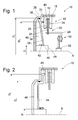
- a wet-running coupling assembly 10 is shown, which may be provided for example as a lock-up clutch in a hydrodynamic torque converter or the like, but equally as a wet-running clutch, so as a so-called wet-running multi-plate clutch may be formed.
- the coupling arrangement 10 comprises a housing arrangement 12, for example with two housing shells, of which in the Fig. 2 a housing side to be positioned housing shell 14 is shown.
- a transmission-side housing shell can form a pump wheel.
- the Housing arrangement 12 is a first friction surface formation 16, comprising two friction elements 18 designed as so-called lamellae, coupled for common rotation about a rotation axis A.
- the housing assembly 12 may be formed with a tooth formation 20, with which the friction elements 18 of the first friction surface formation 16 are in rotational coupling engagement.
- a second friction surface formation 22 comprises a likewise lamella-like friction element 24 with friction linings 26 on both axial sides.
- the friction element 24 is coupled via a Reibelementenarme 28 and possibly a schematically shown Torsionsschwingungsdämpferan Aunt 30 to an effective as a driven member output hub 32.
- a turbine wheel may then be coupled in the torque flow before the torsional vibration damper arrangement, after the torsional vibration damper arrangement or in a multi-stage torsional vibration damper arrangement.
- a ring-shaped pressure piston 34 is provided. This is in its radially outer end portion 36 by means of a formed as an O-ring or the like seal member 38 with respect to the housing assembly 12 fluidly guided in the direction of the axis of rotation A movable. In its radially inner end region 40, the pressing piston 34 is guided in a fluid-tight manner in the direction of the axis of rotation A by means of a sealing element 42, for example with respect to a hub element 44 or the like fixed to the housing arrangement 12.
- a pressure fluid chamber 46 is formed, in which, for example, introduced through the hub 44 through an output shaft or the like supplied pressurized fluid or can be deducted from there.
- a Force on the Anpresskolben 34 exerted, which this in the direction of the friction surface formations 16, 22 to load, to bring the coupling assembly 10 in a state of engagement.
- the pressing piston 34 presses against the friction surface formations 16, 22, here the first friction element 18 of the drive-side friction surface formation 16, with an example of a ring-shaped loading area 48.
- the loading area 48 of the pressing piston 34 lies radially inside the fluid-tight guide with respect to the housing arrangement 12, lies in the in Fig. 2 shown embodiment of the application area 48 radially outside this guide. It can be seen here that the outer diameter D A of the Fluidbeetzschlagungs simulation is smaller than the actual outer diameter of the Anpresskolbens 34.
- the friction surface formations 16, 22 can be configured with a different number of friction elements or lamellae.
- the friction elements of the drive-side friction surface formation 16 may not be coupled directly to the housing arrangement but via a friction element carrier or the like.
- the pressing piston 34 may be guided in its radially inner end region with respect to a module other than the housing assembly or a hub fixed thereto fluid-tight axially movable.
- an output shaft could be guided in the axial region of the Anpresskolbens 34, so that the Anpresskolben 34 could be guided axially movable on such a shaft.
Landscapes
- Engineering & Computer Science (AREA)
- General Engineering & Computer Science (AREA)
- Mechanical Engineering (AREA)
- Hydraulic Clutches, Magnetic Clutches, Fluid Clutches, And Fluid Joints (AREA)
Applications Claiming Priority (2)
| Application Number | Priority Date | Filing Date | Title |
|---|---|---|---|
| DE102008042884 | 2008-10-16 | ||
| DE102009000567A DE102009000567A1 (de) | 2008-10-16 | 2009-02-03 | Nasslaufende Kopplungsanordnung |
Publications (2)
| Publication Number | Publication Date |
|---|---|
| EP2177780A2 true EP2177780A2 (fr) | 2010-04-21 |
| EP2177780A3 EP2177780A3 (fr) | 2013-07-31 |
Family
ID=41531516
Family Applications (1)
| Application Number | Title | Priority Date | Filing Date |
|---|---|---|---|
| EP09172624.0A Withdrawn EP2177780A3 (fr) | 2008-10-16 | 2009-10-09 | Agencement d'accouplement humide |
Country Status (3)
| Country | Link |
|---|---|
| US (1) | US8387766B2 (fr) |
| EP (1) | EP2177780A3 (fr) |
| DE (1) | DE102009000567A1 (fr) |
Families Citing this family (2)
| Publication number | Priority date | Publication date | Assignee | Title |
|---|---|---|---|---|
| DE102008020684A1 (de) * | 2007-05-09 | 2008-11-13 | Luk Lamellen Und Kupplungsbau Beteiligungs Kg | Drehmomentwandler mit Anordnung gegen Rattern und Kühlströmungsanordnung |
| DE102008031955B4 (de) * | 2007-07-31 | 2018-12-20 | Schaeffler Technologies AG & Co. KG | Drehmomentwandler mit vom Kolben zentrierter Kupplungsplatte |
Citations (1)
| Publication number | Priority date | Publication date | Assignee | Title |
|---|---|---|---|---|
| WO2001024720A1 (fr) | 1999-10-05 | 2001-04-12 | Oratec Interventions, Inc. | Instrument chirurgical d'ablation et d'aspiration |
Family Cites Families (8)
| Publication number | Priority date | Publication date | Assignee | Title |
|---|---|---|---|---|
| US5172799A (en) * | 1991-02-08 | 1992-12-22 | Toyota Jidosha Kabushiki Kaisha | Centrifugal hydraulic cancel mechanism for the rotating clutch |
| US6264018B1 (en) * | 1999-02-09 | 2001-07-24 | Exedy Corporation | Lockup device of a torque converter |
| US6932207B2 (en) * | 2000-09-01 | 2005-08-23 | Nsk-Warner K.K. | Wet multiplate clutch |
| DE102005021899A1 (de) * | 2005-05-12 | 2006-11-30 | Zf Friedrichshafen Ag | Kupplung |
| DE102006007011A1 (de) * | 2006-02-15 | 2007-08-16 | Zf Friedrichshafen Ag | Vorrichtung zum Betätigen einer Lamellenkupplung |
| US20070251788A1 (en) | 2006-05-01 | 2007-11-01 | Luk Lamellen Und Kupplungsbau Beteiligungs Kg | Drive plate and seal for a torque converter |
| DE102007039856B4 (de) * | 2006-09-28 | 2018-12-20 | Schaeffler Technologies AG & Co. KG | Kraftübertragungseinrichtung |
| DE102006057915A1 (de) * | 2006-10-11 | 2008-05-15 | Borg Warner Inc., Auburn Hills | Kupplung und Kupplungsanordnung mit einer solchen Kupplung |
-
2009
- 2009-02-03 DE DE102009000567A patent/DE102009000567A1/de not_active Ceased
- 2009-10-09 EP EP09172624.0A patent/EP2177780A3/fr not_active Withdrawn
- 2009-10-16 US US12/580,734 patent/US8387766B2/en not_active Expired - Fee Related
Patent Citations (1)
| Publication number | Priority date | Publication date | Assignee | Title |
|---|---|---|---|---|
| WO2001024720A1 (fr) | 1999-10-05 | 2001-04-12 | Oratec Interventions, Inc. | Instrument chirurgical d'ablation et d'aspiration |
Also Published As
| Publication number | Publication date |
|---|---|
| DE102009000567A1 (de) | 2010-04-22 |
| US20100096231A1 (en) | 2010-04-22 |
| EP2177780A3 (fr) | 2013-07-31 |
| US8387766B2 (en) | 2013-03-05 |
Similar Documents
| Publication | Publication Date | Title |
|---|---|---|
| DE19945475B4 (de) | Kraftübertragungseinrichtung | |
| DE112007002007B4 (de) | Fluidkupplung | |
| DE19722150C2 (de) | Überbrückungskupplung | |
| DE2934708A1 (de) | Hydrodynamischer drehmomentwandler mit ueberbrueckungskupplung | |
| DE10024191A1 (de) | Drehmomentübertragungseinrichtung | |
| DE102007014311A1 (de) | Hydrodynamische Kopplungsvorrichtung | |
| EP3551910B1 (fr) | Dispositif convertisseur de couple destiné en particulier à un groupe motopropulseur d'un véhicule à moteur | |
| DE112011101904T5 (de) | Überbrückungsvorrichtung für einen Drehmomentwandler | |
| DE102007017430B4 (de) | Außenplatte mit Antriebszunge für Bogenfedern für einen Dämpfer eines Drehmomentwandlers | |
| DE102007058417A1 (de) | Turbinen- und Pumpenräder für Drehmomentwandler und Verfahren zur Herstellung | |
| DE10156041A1 (de) | Hydrodynamische Kopplungseinrichtung | |
| DE19835549A1 (de) | Hydrodynamischer Drehmomentwandler | |
| EP1436518B1 (fr) | Systeme d'embrayage | |
| DE102012011819A1 (de) | Baugruppe aus einem Lamellenträger-Zahnkranz und einem Anschlussteil sowie Verfahren zur Befestigung des Zahnkranzes am Anschlussteil | |
| EP1780435A2 (fr) | Embrayage double en forme radial | |
| DE102011089751A1 (de) | Nasslaufende Lamellenkupplung | |
| DE102011003846A1 (de) | Drehmomentübertragungsanordnung, insbesondere hydrodynamischer Drehmomentwandler | |
| EP2177780A2 (fr) | Agencement d'accouplement humide | |
| EP2163780A1 (fr) | Agencement d'accouplement, notamment pour un dispositif d'accouplement hydrodynamique | |
| DE112007002122B4 (de) | Vorrichtung zur Dämpfung von Schwingungen und Kraftübertragungseinrichtung mit einer Vorrichtung zur Dämpfung von Schwingungen | |
| DE10222718A1 (de) | Parksperre eines Getriebes | |
| WO2010051795A1 (fr) | Embrayage à bain d'huile | |
| DE102007014312A1 (de) | Hydrodynamische Kopplungsvorrichtung | |
| WO2008080381A1 (fr) | Dispositif de transmission de force et procédé de commande du travail de friction d'un dispositif pour amortir les vibrations dans un tel dispositif de transmission de force | |
| DE102019122692B4 (de) | Hydrodynamischer Drehmomentwandler mit Wandlerüberbrückungskupplung |
Legal Events
| Date | Code | Title | Description |
|---|---|---|---|
| PUAI | Public reference made under article 153(3) epc to a published international application that has entered the european phase |
Free format text: ORIGINAL CODE: 0009012 |
|
| AK | Designated contracting states |
Kind code of ref document: A2 Designated state(s): AT BE BG CH CY CZ DE DK EE ES FI FR GB GR HR HU IE IS IT LI LT LU LV MC MK MT NL NO PL PT RO SE SI SK SM TR |
|
| AX | Request for extension of the european patent |
Extension state: AL BA RS |
|
| PUAL | Search report despatched |
Free format text: ORIGINAL CODE: 0009013 |
|
| AK | Designated contracting states |
Kind code of ref document: A3 Designated state(s): AT BE BG CH CY CZ DE DK EE ES FI FR GB GR HR HU IE IS IT LI LT LU LV MC MK MT NL NO PL PT RO SE SI SK SM TR |
|
| AX | Request for extension of the european patent |
Extension state: AL BA RS |
|
| RIC1 | Information provided on ipc code assigned before grant |
Ipc: F16D 25/12 20060101ALI20130627BHEP Ipc: F16D 25/0638 20060101AFI20130627BHEP |
|
| STAA | Information on the status of an ep patent application or granted ep patent |
Free format text: STATUS: THE APPLICATION IS DEEMED TO BE WITHDRAWN |
|
| 18D | Application deemed to be withdrawn |
Effective date: 20140201 |