EP2177795A1 - Joint - Google Patents
Joint Download PDFInfo
- Publication number
- EP2177795A1 EP2177795A1 EP09252342A EP09252342A EP2177795A1 EP 2177795 A1 EP2177795 A1 EP 2177795A1 EP 09252342 A EP09252342 A EP 09252342A EP 09252342 A EP09252342 A EP 09252342A EP 2177795 A1 EP2177795 A1 EP 2177795A1
- Authority
- EP
- European Patent Office
- Prior art keywords
- hydraulic
- trap
- oil
- hydraulic seal
- seal
- Prior art date
- Legal status (The legal status is an assumption and is not a legal conclusion. Google has not performed a legal analysis and makes no representation as to the accuracy of the status listed.)
- Granted
Links
- 230000000717 retained effect Effects 0.000 claims abstract description 10
- 238000004891 communication Methods 0.000 claims description 4
- 230000001419 dependent effect Effects 0.000 claims description 2
- 239000012530 fluid Substances 0.000 claims 2
- 239000007788 liquid Substances 0.000 description 14
- 230000000694 effects Effects 0.000 description 8
- 230000002000 scavenging effect Effects 0.000 description 5
- 230000008901 benefit Effects 0.000 description 2
- 238000007654 immersion Methods 0.000 description 2
- 238000004939 coking Methods 0.000 description 1
- 230000008094 contradictory effect Effects 0.000 description 1
- 238000001816 cooling Methods 0.000 description 1
- 238000013461 design Methods 0.000 description 1
- 230000005484 gravity Effects 0.000 description 1
- 238000000034 method Methods 0.000 description 1
- 238000012986 modification Methods 0.000 description 1
- 230000004048 modification Effects 0.000 description 1
- 238000013021 overheating Methods 0.000 description 1
- 238000000926 separation method Methods 0.000 description 1
- 230000001052 transient effect Effects 0.000 description 1
Images


Classifications
-
- F—MECHANICAL ENGINEERING; LIGHTING; HEATING; WEAPONS; BLASTING
- F16—ENGINEERING ELEMENTS AND UNITS; GENERAL MEASURES FOR PRODUCING AND MAINTAINING EFFECTIVE FUNCTIONING OF MACHINES OR INSTALLATIONS; THERMAL INSULATION IN GENERAL
- F16J—PISTONS; CYLINDERS; SEALINGS
- F16J15/00—Sealings
- F16J15/16—Sealings between relatively-moving surfaces
- F16J15/40—Sealings between relatively-moving surfaces by means of fluid
- F16J15/42—Sealings between relatively-moving surfaces by means of fluid kept in sealing position by centrifugal force
Definitions
- This invention relates to seals.
- it relates to hydraulic seals of the type used to provide a seal between two relatively rotating shafts.
- Figure 1 is a sectional view, at top dead centre, of a known hydraulic seal arrangement, as described in US6568688 .
- a low pressure shaft 12 and a high pressure shaft 14 are concentric shafts of a two-shaft gas turbine engine, rotating at different speed about a common axis of rotation 16.
- the high pressure shaft 14 is supported on a bearing 18.
- the hydraulic seal 24 comprises an annulus 26 which is provided in the interior of the high pressure shaft 14 and extends radially outwards across the whole circumference of the shaft 14.
- the annulus is defined by radially inwardly extending walls 27, which extend around the whole circumference of the shaft 14.
- Projecting into the annulus 26 is a web 28 which is arranged on the low pressure shaft 12 and extends radially outward across the whole circumference of the shaft 12.
- oil also enters the annulus 26 through an annular inlet area 36, the annulus 26 lying still further radially outward than the inner wall 34.
- the oil 30 collects in the annulus 26 both to the left and to the right sides of the web 28, creating an optimum siphon-type hydraulic seal as shown.
- the radially inwardly extending side walls defining the annulus 26 act as weirs and limit the oil level within the annulus.
- the surface or liquid level of the oil, on each side of the web 28, will be ultimately constrained by the radially inward extension of the respective side wall. This can be seen in the annular inlet area 36.
- the surface or liquid level 38 of the oil 30 is further radially outward than on the right-hand side of the web 28, because the left-hand side communicates with the region 22, in which the pressure is higher than in the area 20 with which the right-hand side is in communication.
- a scoop plate 40 in the annulus 26 defines a passageway 42, through which excess oil can flow to an outlet duct 44. In this way, a continuous flow of oil is maintained through the hydraulic seal 24.
- Throughflow oil may flow over one of the weirs, typically on the opposite side of the web 28 to the oil jet.
- the amount of heat transferred to the oil is highly dependent on the depth of immersion of the fin 28 in operation.
- weir diameter is made smaller (i.e. the weir is made to extend further radially inward), then more oil can be retained at shutdown, and so the seal can be remade more quickly; but a smaller diameter weir will cause the web to be more deeply immersed in the oil during normal running, and this will increase the amount of heat transferred to the oil during normal running.
- the inventors have devised a hydraulic seal arrangement that reduces or substantially overcomes the problems associated with known hydraulic seal arrangements, permitting a seal without excessive immersion of the web during normal running, but in which sufficient oil can be retained on shutdown to permit an effective hydraulic seal to be remade almost immediately when the engine is restarted.
- the invention provides a hydraulic seal arrangement as set out in the claims.
- a hydraulic seal arrangement according to the invention is shown generally at 210.
- Figure 3 is a cross-section on the line III-III of Figure 2 .
- radially inwardly extending walls 227 define an annulus 226, and a radially outwardly extending web 228 extends between the walls 227.
- a hydraulic seal exit weir 252 defines a passage 254, and in use excess oil can flow through this passage for scavenging.
- Two first passages 254 are provided, at diametrically opposite positions of the seal assembly 210, as can more clearly be seen in Figure 2 .
- the trap 250 extends around the whole circumference of the seal arrangement 210.
- the scavenging means is not shown, but performs essentially the same function as in the embodiment of Figure 1 .
- a pocket 258 is provided in the hydraulic trap 250, by extending the hydraulic trap 250 further radially outward than over the rest of the circumference. The purpose of these pockets 258 will be explained presently.
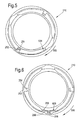
- Figure 5 illustrates the operation of a seal arrangement according to the invention, after engine shutdown and just before the arrangement comes to a standstill.
- the seal arrangement is rotating slowly clockwise, as shown by the arrow 560.
- Figure 6 shows the arrangement of Figure 5 when it has rotated by a further 65 degrees or so in the direction of the arrow 560.
- a quantity of oil 630 is retained in the hydraulic trap 250, up to a liquid level 638. Because the hydraulic trap exit weir 256 is now at bottom dead centre, any excess oil will escape over the weir 256 for scavenging.
- the presence of the pockets 258 increases the amount of oil 630 that can be retained in the hydraulic trap 250, when the hydraulic trap exit weir 256 is at bottom dead centre. Because the rest of the circumference of the hydraulic trap 250 does not have pockets 258, the liquid level will be higher when any other part of the hydraulic trap 250 is a bottom dead centre. This can be seen by comparing the liquid level 538 in Figure 5 with the liquid level 638 in Figure 6 .
- the advantage of this is that the relatively high liquid level 538, when the hydraulic seal exit weir 252 is at or near bottom dead centre, will prevent further oil leakage out of the hydraulic seal annulus 226; while the relatively low liquid level 638, when the hydraulic trap exit weir 256 is at or near bottom dead centre, will prevent oil leakage out of the hydraulic trap 250. If the pockets 258 were not provided and the liquid level were uniform, the trap 250 would spill a small volume of oil each time its exit weir 256 approached bottom dead centre, which would be refilled from the hydraulic seal 226 as its exit weir 252 approached bottom dead centre. In this way, the hydraulic seal annulus 226 could slowly drain until it retained insufficient oil to re-make the hydraulic seal on startup.
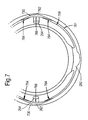
- Figure 7 illustrates a further, optional feature of a seal arrangement according to the invention.
- the radially inner wall 759 of the hydraulic trap 250 in the region of each of the two first passages 254, is moved radially outwards.
- the radially outer wall 761 of the hydraulic trap 250 is similarly moved radially outwards so that a recess or U-trap 762 is formed in the region of each of the two first passages 254. It can be seen that within the recesses 762, the radially inner wall 759 lies radially outward of the normal radial position of the radially outer wall 761 around the rest of the circumference.
- some of the oil 730 from the hydraulic trap 250 will flow into the recesses 762.
- Centrifugal forces 764 act against the forces 766 (which arise because the pressure in the hydraulic seal annulus 226 is higher than that in the hydraulic trap 250) so that the two regions 730 of oil act to seal the passage 254 in the hydraulic seal exit weir 252. This prevents the leakage of air out of the hydraulic seal annulus 226 into the hydraulic trap 250, which would otherwise occur until the flow of oil is re-established through the seal arrangement 210 (as described above with reference to Figure 3 .
- two weirs are provided between the seal and the trap, and two between the trap and the scavenge.
- the invention may alternatively be put into effect with a different number of weirs in either of these two locations.
- the weirs in the embodiment described are separated at 90 degrees from one another, but may be at different angular separations.
Landscapes
- Engineering & Computer Science (AREA)
- General Engineering & Computer Science (AREA)
- Mechanical Engineering (AREA)
- Sealing Using Fluids, Sealing Without Contact, And Removal Of Oil (AREA)
- Turbine Rotor Nozzle Sealing (AREA)
Applications Claiming Priority (1)
| Application Number | Priority Date | Filing Date | Title |
|---|---|---|---|
| GBGB0818726.2A GB0818726D0 (en) | 2008-10-14 | 2008-10-14 | A seal |
Publications (2)
| Publication Number | Publication Date |
|---|---|
| EP2177795A1 true EP2177795A1 (fr) | 2010-04-21 |
| EP2177795B1 EP2177795B1 (fr) | 2012-07-25 |
Family
ID=40083928
Family Applications (1)
| Application Number | Title | Priority Date | Filing Date |
|---|---|---|---|
| EP09252342A Not-in-force EP2177795B1 (fr) | 2008-10-14 | 2009-10-01 | Joint |
Country Status (4)
| Country | Link |
|---|---|
| US (1) | US9133939B2 (fr) |
| EP (1) | EP2177795B1 (fr) |
| JP (1) | JP5680293B2 (fr) |
| GB (1) | GB0818726D0 (fr) |
Cited By (2)
| Publication number | Priority date | Publication date | Assignee | Title |
|---|---|---|---|---|
| EP2740976A1 (fr) * | 2012-12-06 | 2014-06-11 | Rolls-Royce plc | Agencement de joint hydraulique |
| EP3112729A1 (fr) * | 2015-06-30 | 2017-01-04 | Rolls-Royce plc | Joint |
Families Citing this family (4)
| Publication number | Priority date | Publication date | Assignee | Title |
|---|---|---|---|---|
| GB0818726D0 (en) * | 2008-10-14 | 2008-11-19 | Rolls Royce Plc | A seal |
| US10753219B2 (en) * | 2015-05-26 | 2020-08-25 | Pratt & Whitney Canada Corp. | Internally cooled seal runner and method of cooling seal runner of a gas turbine engine |
| US10371263B2 (en) | 2017-06-23 | 2019-08-06 | United Technologies Corporation | Hydraulic seal for non-mainshaft, rotating to static |
| CN109488768A (zh) * | 2018-11-16 | 2019-03-19 | 蔡嘉丽 | 一种高速转动轴的密封结构 |
Citations (4)
| Publication number | Priority date | Publication date | Assignee | Title |
|---|---|---|---|---|
| DE2343724A1 (de) * | 1973-05-07 | 1974-11-21 | Rigaku Denki Co Ltd | Vakuumabdichtung fuer drehwellen |
| US6568688B1 (en) | 1999-04-14 | 2003-05-27 | Rolls-Royce Deutschland Ltd & Co Kg | Hydraulic seal arrangement, more particularly on a gas turbine |
| DE102005047696A1 (de) * | 2005-09-27 | 2007-03-29 | Rolls-Royce Deutschland Ltd & Co Kg | Siphonartige hydraulische Dichtung zwischen zwei konzentrisch angeordneten Wellen |
| EP2071131A2 (fr) * | 2007-12-14 | 2009-06-17 | Rolls-Royce Deutschland Ltd & Co KG | Etanchéification d'au moins un arbre à l'aide d'au moins un joint hydraulique |
Family Cites Families (26)
| Publication number | Priority date | Publication date | Assignee | Title |
|---|---|---|---|---|
| US822802A (en) * | 1905-11-24 | 1906-06-05 | Wilkinson Turbine Company | Shaft-packing. |
| US1558630A (en) * | 1924-02-18 | 1925-10-27 | Ingersoll Rand Co | Hydraulic seal for rotary engines |
| US1749586A (en) * | 1924-03-28 | 1930-03-04 | Westinghouse Electric & Mfg Co | Oil-sealing ring for turbine bearings |
| US2573425A (en) * | 1947-06-23 | 1951-10-30 | Ethel K Haferkamp | Seal for centrifugal machines |
| US2823052A (en) * | 1954-04-12 | 1958-02-11 | Gen Motors Corp | Fluid seal device |
| US3476396A (en) * | 1964-04-14 | 1969-11-04 | Daimler Benz Ag | Shaft seal with return rifling |
| GB1212593A (en) | 1968-01-25 | 1970-11-18 | British Aircraft Corp Ltd | Improvements relating to rotary large diameter gas seals |
| JPS49135063A (fr) * | 1973-05-07 | 1974-12-26 | ||
| FR2340490A1 (fr) * | 1976-02-04 | 1977-09-02 | Legoy Auguste | Dispositif d'etancheite pour machine rotative a fluide hydraulique |
| JPS54151085U (fr) * | 1978-04-12 | 1979-10-20 | ||
| DE2846823A1 (de) * | 1978-10-27 | 1980-04-30 | Opel Adam Ag | Anordnung zur abdichtung des durchganges antriebswelle/gehaeuse bei waelzkoerper-fluessigkeitspumpen, insbesondere oelpumpen von kraftfahrzeugen |
| JPS5833798U (ja) * | 1981-08-31 | 1983-03-04 | 株式会社東芝 | ポンプ封水装置 |
| JPS5833799U (ja) * | 1981-08-31 | 1983-03-04 | 株式会社東芝 | 封水装置 |
| GB2125118A (en) * | 1982-08-03 | 1984-02-29 | Rolls Royce | Hydraulic seal |
| GB8318582D0 (en) * | 1983-07-08 | 1983-08-10 | Rolls Royce | Air separation and lubricant scavenge apparatus |
| JPS62261765A (ja) * | 1986-05-06 | 1987-11-13 | Matsushita Seiko Co Ltd | 空気調和機のフアン軸シ−ル装置 |
| JPH0663573B2 (ja) * | 1990-01-30 | 1994-08-22 | 東海旅客鉄道株式会社 | 歯車装置の軸受密封装置 |
| JPH0953594A (ja) * | 1995-08-09 | 1997-02-25 | I T T Frygt Kk | 遠心ポンプのシール構造 |
| GB9801561D0 (en) * | 1998-01-27 | 1998-03-25 | Rolls Royce Plc | Hydraulic seal |
| JP2003148632A (ja) * | 2001-11-12 | 2003-05-21 | Ishikawajima Harima Heavy Ind Co Ltd | 回転機械の回転軸シール機構 |
| DE10201055A1 (de) * | 2002-01-14 | 2003-07-24 | Rolls Royce Deutschland | Hydraulische Dichtungsanordnung |
| US6845987B2 (en) * | 2002-09-10 | 2005-01-25 | United Technologies Corporation | Shaft seal |
| JP2006004716A (ja) * | 2004-06-16 | 2006-01-05 | Koyo Seiko Co Ltd | 回転陽極型x線管 |
| DE102004040242A1 (de) * | 2004-08-13 | 2006-02-23 | Rolls-Royce Deutschland Ltd & Co Kg | Hydraulische Wellendichtung für den Hochtemperaturbereich |
| JP2009019608A (ja) * | 2007-07-13 | 2009-01-29 | Ihi Corp | ハイドロリックシール構造 |
| GB0818726D0 (en) * | 2008-10-14 | 2008-11-19 | Rolls Royce Plc | A seal |
-
2008
- 2008-10-14 GB GBGB0818726.2A patent/GB0818726D0/en not_active Ceased
-
2009
- 2009-10-01 EP EP09252342A patent/EP2177795B1/fr not_active Not-in-force
- 2009-10-01 US US12/588,050 patent/US9133939B2/en active Active
- 2009-10-13 JP JP2009235919A patent/JP5680293B2/ja not_active Expired - Fee Related
Patent Citations (4)
| Publication number | Priority date | Publication date | Assignee | Title |
|---|---|---|---|---|
| DE2343724A1 (de) * | 1973-05-07 | 1974-11-21 | Rigaku Denki Co Ltd | Vakuumabdichtung fuer drehwellen |
| US6568688B1 (en) | 1999-04-14 | 2003-05-27 | Rolls-Royce Deutschland Ltd & Co Kg | Hydraulic seal arrangement, more particularly on a gas turbine |
| DE102005047696A1 (de) * | 2005-09-27 | 2007-03-29 | Rolls-Royce Deutschland Ltd & Co Kg | Siphonartige hydraulische Dichtung zwischen zwei konzentrisch angeordneten Wellen |
| EP2071131A2 (fr) * | 2007-12-14 | 2009-06-17 | Rolls-Royce Deutschland Ltd & Co KG | Etanchéification d'au moins un arbre à l'aide d'au moins un joint hydraulique |
Cited By (4)
| Publication number | Priority date | Publication date | Assignee | Title |
|---|---|---|---|---|
| EP2740976A1 (fr) * | 2012-12-06 | 2014-06-11 | Rolls-Royce plc | Agencement de joint hydraulique |
| US9157532B2 (en) | 2012-12-06 | 2015-10-13 | Rolls-Royce Plc | Hydraulic seal arrangement |
| EP3112729A1 (fr) * | 2015-06-30 | 2017-01-04 | Rolls-Royce plc | Joint |
| US10119420B2 (en) | 2015-06-30 | 2018-11-06 | Rolls-Royce Plc | Seal |
Also Published As
| Publication number | Publication date |
|---|---|
| EP2177795B1 (fr) | 2012-07-25 |
| JP5680293B2 (ja) | 2015-03-04 |
| GB0818726D0 (en) | 2008-11-19 |
| US20100090415A1 (en) | 2010-04-15 |
| JP2010107038A (ja) | 2010-05-13 |
| US9133939B2 (en) | 2015-09-15 |
Similar Documents
| Publication | Publication Date | Title |
|---|---|---|
| EP2177795B1 (fr) | Joint | |
| US4531746A (en) | Dual labyrinth fluid seal with fluid slinger | |
| JP3555685B2 (ja) | 流体作動システムにおける浄化装置 | |
| SE456028B (sv) | Ringformig vetskepump med konisk eller cylindrisk portdel | |
| US10119420B2 (en) | Seal | |
| GB2290113A (en) | Centrifugal pump shaft seal cooling and venting | |
| JP2006234147A (ja) | ジャーナル軸受およびこのジャーナル軸受を組み込んだ回転機械 | |
| US4570947A (en) | Gas sealing and fluid scavenge apparatus | |
| JP2008121488A (ja) | ウォータポンプ | |
| EP2740976B1 (fr) | Agencement de joint hydraulique | |
| JP2012202507A (ja) | 軸受装置およびポンプ装置 | |
| KR19990082659A (ko) | 베어링 장치로부터 액체 윤활재를 배출시키기 위한장치 및 방법 | |
| EP0786582B1 (fr) | Dispositif de palier pour machine rotative à axe vertical | |
| US4643593A (en) | Assembly for lubricating thrust bearings of machines | |
| JP2726484B2 (ja) | 横軸回転機の軸受給油装置 | |
| US5863133A (en) | Vertical bearing assembly lubrication | |
| JP3148087B2 (ja) | 立軸形排水ポンプ及び立軸形排水ポンプ用軸封装置 | |
| JPS6214453Y2 (fr) | ||
| JPH02125108A (ja) | 横軸回転機の軸受装置 | |
| JP2022169190A (ja) | 水中軸受構造、立軸ポンプ、ポンプシステム及び潤滑液の供給方法 | |
| Evans et al. | Enhanced performance with laser-etched seal face technology | |
| EP1712817A1 (fr) | Joint d'étanchéite imperméable à l'eau pour transmission | |
| JPH08121383A (ja) | 流体機械のフローティングリングシール装置 | |
| JPS5916132B2 (ja) | ランナ−軸振動低減装置 | |
| CN106764358A (zh) | 集油、导油一体化的高承载自润滑滑动轴承 |
Legal Events
| Date | Code | Title | Description |
|---|---|---|---|
| PUAI | Public reference made under article 153(3) epc to a published international application that has entered the european phase |
Free format text: ORIGINAL CODE: 0009012 |
|
| AK | Designated contracting states |
Kind code of ref document: A1 Designated state(s): AT BE BG CH CY CZ DE DK EE ES FI FR GB GR HR HU IE IS IT LI LT LU LV MC MK MT NL NO PL PT RO SE SI SK SM TR |
|
| AX | Request for extension of the european patent |
Extension state: AL BA RS |
|
| 17P | Request for examination filed |
Effective date: 20100401 |
|
| 17Q | First examination report despatched |
Effective date: 20100511 |
|
| GRAP | Despatch of communication of intention to grant a patent |
Free format text: ORIGINAL CODE: EPIDOSNIGR1 |
|
| RIC1 | Information provided on ipc code assigned before grant |
Ipc: F16J 15/42 20060101AFI20120131BHEP |
|
| GRAS | Grant fee paid |
Free format text: ORIGINAL CODE: EPIDOSNIGR3 |
|
| GRAA | (expected) grant |
Free format text: ORIGINAL CODE: 0009210 |
|
| AK | Designated contracting states |
Kind code of ref document: B1 Designated state(s): AT BE BG CH CY CZ DE DK EE ES FI FR GB GR HR HU IE IS IT LI LT LU LV MC MK MT NL NO PL PT RO SE SI SK SM TR |
|
| REG | Reference to a national code |
Ref country code: GB Ref legal event code: FG4D |
|
| REG | Reference to a national code |
Ref country code: CH Ref legal event code: EP |
|
| REG | Reference to a national code |
Ref country code: AT Ref legal event code: REF Ref document number: 567854 Country of ref document: AT Kind code of ref document: T Effective date: 20120815 Ref country code: IE Ref legal event code: FG4D |
|
| REG | Reference to a national code |
Ref country code: DE Ref legal event code: R096 Ref document number: 602009008476 Country of ref document: DE Effective date: 20120920 |
|
| REG | Reference to a national code |
Ref country code: NL Ref legal event code: VDEP Effective date: 20120725 |
|
| REG | Reference to a national code |
Ref country code: AT Ref legal event code: MK05 Ref document number: 567854 Country of ref document: AT Kind code of ref document: T Effective date: 20120725 |
|
| REG | Reference to a national code |
Ref country code: LT Ref legal event code: MG4D Effective date: 20120725 |
|
| PG25 | Lapsed in a contracting state [announced via postgrant information from national office to epo] |
Ref country code: HR Free format text: LAPSE BECAUSE OF FAILURE TO SUBMIT A TRANSLATION OF THE DESCRIPTION OR TO PAY THE FEE WITHIN THE PRESCRIBED TIME-LIMIT Effective date: 20120725 Ref country code: IS Free format text: LAPSE BECAUSE OF FAILURE TO SUBMIT A TRANSLATION OF THE DESCRIPTION OR TO PAY THE FEE WITHIN THE PRESCRIBED TIME-LIMIT Effective date: 20121125 Ref country code: BE Free format text: LAPSE BECAUSE OF FAILURE TO SUBMIT A TRANSLATION OF THE DESCRIPTION OR TO PAY THE FEE WITHIN THE PRESCRIBED TIME-LIMIT Effective date: 20120725 Ref country code: CY Free format text: LAPSE BECAUSE OF FAILURE TO SUBMIT A TRANSLATION OF THE DESCRIPTION OR TO PAY THE FEE WITHIN THE PRESCRIBED TIME-LIMIT Effective date: 20120725 Ref country code: NO Free format text: LAPSE BECAUSE OF FAILURE TO SUBMIT A TRANSLATION OF THE DESCRIPTION OR TO PAY THE FEE WITHIN THE PRESCRIBED TIME-LIMIT Effective date: 20121025 Ref country code: LT Free format text: LAPSE BECAUSE OF FAILURE TO SUBMIT A TRANSLATION OF THE DESCRIPTION OR TO PAY THE FEE WITHIN THE PRESCRIBED TIME-LIMIT Effective date: 20120725 Ref country code: FI Free format text: LAPSE BECAUSE OF FAILURE TO SUBMIT A TRANSLATION OF THE DESCRIPTION OR TO PAY THE FEE WITHIN THE PRESCRIBED TIME-LIMIT Effective date: 20120725 Ref country code: AT Free format text: LAPSE BECAUSE OF FAILURE TO SUBMIT A TRANSLATION OF THE DESCRIPTION OR TO PAY THE FEE WITHIN THE PRESCRIBED TIME-LIMIT Effective date: 20120725 |
|
| PG25 | Lapsed in a contracting state [announced via postgrant information from national office to epo] |
Ref country code: GR Free format text: LAPSE BECAUSE OF FAILURE TO SUBMIT A TRANSLATION OF THE DESCRIPTION OR TO PAY THE FEE WITHIN THE PRESCRIBED TIME-LIMIT Effective date: 20121026 Ref country code: PT Free format text: LAPSE BECAUSE OF FAILURE TO SUBMIT A TRANSLATION OF THE DESCRIPTION OR TO PAY THE FEE WITHIN THE PRESCRIBED TIME-LIMIT Effective date: 20121126 Ref country code: SI Free format text: LAPSE BECAUSE OF FAILURE TO SUBMIT A TRANSLATION OF THE DESCRIPTION OR TO PAY THE FEE WITHIN THE PRESCRIBED TIME-LIMIT Effective date: 20120725 Ref country code: LV Free format text: LAPSE BECAUSE OF FAILURE TO SUBMIT A TRANSLATION OF THE DESCRIPTION OR TO PAY THE FEE WITHIN THE PRESCRIBED TIME-LIMIT Effective date: 20120725 Ref country code: PL Free format text: LAPSE BECAUSE OF FAILURE TO SUBMIT A TRANSLATION OF THE DESCRIPTION OR TO PAY THE FEE WITHIN THE PRESCRIBED TIME-LIMIT Effective date: 20120725 Ref country code: SE Free format text: LAPSE BECAUSE OF FAILURE TO SUBMIT A TRANSLATION OF THE DESCRIPTION OR TO PAY THE FEE WITHIN THE PRESCRIBED TIME-LIMIT Effective date: 20120725 |
|
| PG25 | Lapsed in a contracting state [announced via postgrant information from national office to epo] |
Ref country code: NL Free format text: LAPSE BECAUSE OF FAILURE TO SUBMIT A TRANSLATION OF THE DESCRIPTION OR TO PAY THE FEE WITHIN THE PRESCRIBED TIME-LIMIT Effective date: 20120725 |
|
| PG25 | Lapsed in a contracting state [announced via postgrant information from national office to epo] |
Ref country code: ES Free format text: LAPSE BECAUSE OF FAILURE TO SUBMIT A TRANSLATION OF THE DESCRIPTION OR TO PAY THE FEE WITHIN THE PRESCRIBED TIME-LIMIT Effective date: 20121105 Ref country code: RO Free format text: LAPSE BECAUSE OF FAILURE TO SUBMIT A TRANSLATION OF THE DESCRIPTION OR TO PAY THE FEE WITHIN THE PRESCRIBED TIME-LIMIT Effective date: 20120725 Ref country code: DK Free format text: LAPSE BECAUSE OF FAILURE TO SUBMIT A TRANSLATION OF THE DESCRIPTION OR TO PAY THE FEE WITHIN THE PRESCRIBED TIME-LIMIT Effective date: 20120725 Ref country code: CZ Free format text: LAPSE BECAUSE OF FAILURE TO SUBMIT A TRANSLATION OF THE DESCRIPTION OR TO PAY THE FEE WITHIN THE PRESCRIBED TIME-LIMIT Effective date: 20120725 Ref country code: EE Free format text: LAPSE BECAUSE OF FAILURE TO SUBMIT A TRANSLATION OF THE DESCRIPTION OR TO PAY THE FEE WITHIN THE PRESCRIBED TIME-LIMIT Effective date: 20120725 |
|
| PG25 | Lapsed in a contracting state [announced via postgrant information from national office to epo] |
Ref country code: IT Free format text: LAPSE BECAUSE OF FAILURE TO SUBMIT A TRANSLATION OF THE DESCRIPTION OR TO PAY THE FEE WITHIN THE PRESCRIBED TIME-LIMIT Effective date: 20120725 Ref country code: SK Free format text: LAPSE BECAUSE OF FAILURE TO SUBMIT A TRANSLATION OF THE DESCRIPTION OR TO PAY THE FEE WITHIN THE PRESCRIBED TIME-LIMIT Effective date: 20120725 Ref country code: MC Free format text: LAPSE BECAUSE OF NON-PAYMENT OF DUE FEES Effective date: 20121031 |
|
| PLBE | No opposition filed within time limit |
Free format text: ORIGINAL CODE: 0009261 |
|
| STAA | Information on the status of an ep patent application or granted ep patent |
Free format text: STATUS: NO OPPOSITION FILED WITHIN TIME LIMIT |
|
| 26N | No opposition filed |
Effective date: 20130426 |
|
| REG | Reference to a national code |
Ref country code: IE Ref legal event code: MM4A |
|
| PG25 | Lapsed in a contracting state [announced via postgrant information from national office to epo] |
Ref country code: IE Free format text: LAPSE BECAUSE OF NON-PAYMENT OF DUE FEES Effective date: 20121001 Ref country code: BG Free format text: LAPSE BECAUSE OF FAILURE TO SUBMIT A TRANSLATION OF THE DESCRIPTION OR TO PAY THE FEE WITHIN THE PRESCRIBED TIME-LIMIT Effective date: 20121025 |
|
| REG | Reference to a national code |
Ref country code: DE Ref legal event code: R097 Ref document number: 602009008476 Country of ref document: DE Effective date: 20130426 |
|
| PG25 | Lapsed in a contracting state [announced via postgrant information from national office to epo] |
Ref country code: MT Free format text: LAPSE BECAUSE OF FAILURE TO SUBMIT A TRANSLATION OF THE DESCRIPTION OR TO PAY THE FEE WITHIN THE PRESCRIBED TIME-LIMIT Effective date: 20120725 |
|
| PG25 | Lapsed in a contracting state [announced via postgrant information from national office to epo] |
Ref country code: TR Free format text: LAPSE BECAUSE OF FAILURE TO SUBMIT A TRANSLATION OF THE DESCRIPTION OR TO PAY THE FEE WITHIN THE PRESCRIBED TIME-LIMIT Effective date: 20120725 |
|
| PG25 | Lapsed in a contracting state [announced via postgrant information from national office to epo] |
Ref country code: LU Free format text: LAPSE BECAUSE OF NON-PAYMENT OF DUE FEES Effective date: 20121001 Ref country code: SM Free format text: LAPSE BECAUSE OF FAILURE TO SUBMIT A TRANSLATION OF THE DESCRIPTION OR TO PAY THE FEE WITHIN THE PRESCRIBED TIME-LIMIT Effective date: 20120725 |
|
| REG | Reference to a national code |
Ref country code: CH Ref legal event code: PL |
|
| PG25 | Lapsed in a contracting state [announced via postgrant information from national office to epo] |
Ref country code: LI Free format text: LAPSE BECAUSE OF NON-PAYMENT OF DUE FEES Effective date: 20131031 Ref country code: HU Free format text: LAPSE BECAUSE OF FAILURE TO SUBMIT A TRANSLATION OF THE DESCRIPTION OR TO PAY THE FEE WITHIN THE PRESCRIBED TIME-LIMIT Effective date: 20091001 Ref country code: CH Free format text: LAPSE BECAUSE OF NON-PAYMENT OF DUE FEES Effective date: 20131031 |
|
| PG25 | Lapsed in a contracting state [announced via postgrant information from national office to epo] |
Ref country code: MK Free format text: LAPSE BECAUSE OF FAILURE TO SUBMIT A TRANSLATION OF THE DESCRIPTION OR TO PAY THE FEE WITHIN THE PRESCRIBED TIME-LIMIT Effective date: 20120725 |
|
| REG | Reference to a national code |
Ref country code: FR Ref legal event code: PLFP Year of fee payment: 7 |
|
| REG | Reference to a national code |
Ref country code: FR Ref legal event code: PLFP Year of fee payment: 8 |
|
| REG | Reference to a national code |
Ref country code: FR Ref legal event code: PLFP Year of fee payment: 9 |
|
| REG | Reference to a national code |
Ref country code: FR Ref legal event code: PLFP Year of fee payment: 10 |
|
| PGFP | Annual fee paid to national office [announced via postgrant information from national office to epo] |
Ref country code: DE Payment date: 20201228 Year of fee payment: 12 |
|
| REG | Reference to a national code |
Ref country code: DE Ref legal event code: R119 Ref document number: 602009008476 Country of ref document: DE |
|
| PG25 | Lapsed in a contracting state [announced via postgrant information from national office to epo] |
Ref country code: DE Free format text: LAPSE BECAUSE OF NON-PAYMENT OF DUE FEES Effective date: 20220503 |
|
| PGFP | Annual fee paid to national office [announced via postgrant information from national office to epo] |
Ref country code: FR Payment date: 20221024 Year of fee payment: 14 |
|
| PGFP | Annual fee paid to national office [announced via postgrant information from national office to epo] |
Ref country code: GB Payment date: 20221018 Year of fee payment: 14 |
|
| P01 | Opt-out of the competence of the unified patent court (upc) registered |
Effective date: 20230528 |
|
| GBPC | Gb: european patent ceased through non-payment of renewal fee |
Effective date: 20231001 |
|
| PG25 | Lapsed in a contracting state [announced via postgrant information from national office to epo] |
Ref country code: GB Free format text: LAPSE BECAUSE OF NON-PAYMENT OF DUE FEES Effective date: 20231001 |
|
| PG25 | Lapsed in a contracting state [announced via postgrant information from national office to epo] |
Ref country code: GB Free format text: LAPSE BECAUSE OF NON-PAYMENT OF DUE FEES Effective date: 20231001 Ref country code: FR Free format text: LAPSE BECAUSE OF NON-PAYMENT OF DUE FEES Effective date: 20231031 |