EP2178155B1 - Coupleur directif doté d'une compensation de la netteté d'orientation par adaptation ciblée des erreurs - Google Patents
Coupleur directif doté d'une compensation de la netteté d'orientation par adaptation ciblée des erreurs Download PDFInfo
- Publication number
- EP2178155B1 EP2178155B1 EP09010935.6A EP09010935A EP2178155B1 EP 2178155 B1 EP2178155 B1 EP 2178155B1 EP 09010935 A EP09010935 A EP 09010935A EP 2178155 B1 EP2178155 B1 EP 2178155B1
- Authority
- EP
- European Patent Office
- Prior art keywords
- terminal
- directional coupler
- signals
- terminating impedance
- signal
- Prior art date
- Legal status (The legal status is an assumption and is not a legal conclusion. Google has not performed a legal analysis and makes no representation as to the accuracy of the status listed.)
- Active
Links
Images
Classifications
-
- H—ELECTRICITY
- H01—ELECTRIC ELEMENTS
- H01P—WAVEGUIDES; RESONATORS, LINES, OR OTHER DEVICES OF THE WAVEGUIDE TYPE
- H01P5/00—Coupling devices of the waveguide type
- H01P5/12—Coupling devices having more than two ports
- H01P5/16—Conjugate devices, i.e. devices having at least one port decoupled from one other port
- H01P5/18—Conjugate devices, i.e. devices having at least one port decoupled from one other port consisting of two coupled guides, e.g. directional couplers
- H01P5/184—Conjugate devices, i.e. devices having at least one port decoupled from one other port consisting of two coupled guides, e.g. directional couplers the guides being strip lines or microstrips
Definitions
- the invention relates to a directional coupler for directional transmission of high-frequency signals.
- a directivity of more than 30 dB can be achieved with conventional construction only with a three-layered or mechanically very complex structure or by an explicit optimization of the directivity of each directional coupler during manufacture.
- JP 2008 219175 A shows a directional coupler whose isolation terminal is connected to a termination.
- the invention is based on the object to provide a directional coupler, which achieves a high level of quality with low production costs and small footprint.
- a directional coupler has at least four terminals located at the ends of two closely spaced strip lines and a termination impedance.
- the directional coupler is configured to couple signals from a first terminal to a third terminal with low attenuation, and to couple signals from a second terminal to the third terminal with very high attenuation.
- the directional coupler is configured such that signals from the first port couple to a fourth port with very high attenuation and that signals from the second port couple to the fourth port with low attenuation.
- the fourth connection is connected to the terminating impedance.
- the termination impedance is dimensioned to cause a targeted mismatch of the fourth terminal and a reflection of a portion of a signal received at the fourth terminal.
- the signal reflected at the fourth terminal and a signal applied to the third terminal interfere at least partially destructively.
- the terminating impedance is dimensioned such that it causes a phase difference of the signal reflected at the fourth terminal with respect to the signal arriving at the third terminal of 180 °.
- the terminating impedance is an ohmic resistance and an inductance and a capacitance. So is a very high directivity with low frequency selectivity and low Guaranteed production costs. Even a small footprint is the result.
- the directional coupler includes at least two strip lines.
- a first stripline preferably connects the first terminal to the second terminal.
- a second stripline preferably connects the third terminal to the fourth terminal.
- the two strip lines are preferably arranged in spatial proximity to one another. This makes it possible to use common directional couplers. Stripline directional couplers are also very easy to manufacture and only require a small footprint.
- the terminating impedance is preferably dimensioned such that the amplitudes of the signal reflected at the fourth terminal and the signal arriving at the third terminal are substantially identical.
- the directional coupler is advantageously constructed in such a way that signals coupled from the first terminal or the second terminal to the third terminal and to the fourth terminal are phase-shifted by a certain angle.
- the terminating impedance can be selectively selected to make the phase difference of the signal reflected at the fourth terminal from the signal input at the third terminal to 180 °.
- the directional coupler is preferably constructed in such a way that signals coupled from the first connection or the second connection to the third connection and to the fourth connection are phase-shifted by 180 °. That's one Setting the phase shift by the terminating impedance not necessary.
- FIG. 1 an exemplary directional coupler 1 is shown.
- a first strip line 2 has the connections 10, 11.
- a second strip line 3 has the connections 12, 13.
- the two strip lines 2, 3 are arranged in a large spatial proximity on a substrate, not shown here.
- signals couple to terminal 12 with low attenuation, and to terminal 13 with high attenuation.
- Signals applied to terminal 11 couple with less Damping to port 13, and high damping to port 12.
- a signal is applied to terminal 11.
- the signal is applied to the first stripline 2 and couples to the second stripline 3. Since the terminals 12, 13 of the second stripline 3 are not terminated in this example, a significant portion of the signal coupled to the terminal 13 is reflected. This significantly deteriorates the directivity of the directional coupler. By an adapted termination on the terminal 13, this can be avoided to some extent. However, such a conclusion is frequency-selective, which causes a frequency dependence of the directivity.
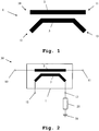
- Fig. 2 shows an embodiment of the directional coupler according to the invention.
- the directional coupler 30 shown here has the connections 10, 11, 12, 13.
- the directional coupler according to the invention additionally includes a terminating impedance 20 connected to the connection 13.
- the terminating impedance 20 is furthermore connected to a ground connection 21.
- a conventional directional coupler 1 is used within the directional coupler 30 according to the invention. This can be both a stripline directional coupler, as in Fig. 1 represented, as well as any directional coupler be of a different design.
- a pure ohmic resistance is connected as a terminating impedance 20 to the terminal 13.
- the terminal 11 is selectively mismatched by the terminating impedance 20. This results in the reflection of a part of the signal applied to the terminal 13.
- the terminating impedance 20 is selected such that the attenuation of the signal reflected at the terminal 13 corresponds to the attenuation of the signal coupled to the terminal 12. In this example, both attenuations are set to -35dB.
- Phase difference is less than 180 °, so this phase difference must be adjusted by means of the terminating impedance 20.
- the terminating impedance 20 By using inductors, capacitors and ohmic resistors, a phase jump of the reflected signal at the terminal 13 is intentionally caused. However, such an artificially induced phase shift has a certain frequency selectivity. An optimal directivity is thus only in a small frequency range too achieve.
- a terminating impedance is used which is lower than in the case of a matched termination. A phase jump is achieved so reliably.
Landscapes
- Cable Transmission Systems, Equalization Of Radio And Reduction Of Echo (AREA)
- Variable-Direction Aerials And Aerial Arrays (AREA)
- Dc Digital Transmission (AREA)
Claims (5)
- Coupleur directionnel (30) comprenant au moins quatre connexions (10, 11, 12, 13), qui se situent aux extrémités de deux lignes micro-ruban (2, 3) agencées à proximité l'un de l'autre, et une impédance de terminaison (20),
dans lequel le coupleur directionnel (30) est conçu de telle manière que les signaux provenant d'une première connexion (10) se couplent à une troisième connexion (12) avec une faible atténuation,
dans lequel les signaux provenant d'une deuxième connexion (11) se couplent à la troisième connexion (12) avec une forte atténuation,
dans lequel les signaux provenant de la première connexion (10) se couplent à une quatrième connexion (13) avec une forte atténuation,
dans lequel les signaux provenant de la deuxième connexion (11) se couplent à la quatrième connexion (13) avec une faible atténuation,
dans lequel la quatrième connexion (13) est reliée à l'impédance de terminaison (20),
dans lequel l'impédance de terminaison (20) est dimensionnée de manière à provoquer une désadaptation ciblée de la quatrième connexion (13) par rapport à l'une des lignes micro-ruban (3) et une réflexion d'une partie d'un signal sur la quatrième connexion (13),
dans lequel le signal réfléchi sur la quatrième connexion (13) et un signal appliqué sur la troisième connexion (12) interfèrent de manière destructive au moins en partie sur une des lignes micro-ruban (3),
dans lequel l'impédance de terminaison (20) est dimensionnée de manière à provoquer une différence de phase de 180° du signal réfléchi sur la quatrième connexion (13) par rapport au signal entrant sur la troisième connexion (12),
dans lequel l'impédance de terminaison (20) est une résistance ohmique et une inductance et une capacité,
dans lequel le coupleur directionnel (30) comporte au moins une désadaptation de la première connexion (10) et/ou de la deuxième connexion (11) et/ou de la troisième connexion (12), et
dans lequel la au moins une désadaptation est réalisée de manière à continuer de contribuer à l'interférence destructive des signaux sur la troisième connexion (12). - Coupleur directionnel selon la revendication 1,
dans lequel le coupleur directionnel (30) comporte au moins deux lignes micro-ruban (2, 3),
dans lequel une première ligne micro-ruban (2) relie la première connexion (10) à la deuxième connexion (11),
dans lequel une deuxième ligne micro-ruban (3) relie la troisième connexion (12) à la quatrième connexion (13), et
dans lequel les deux lignes micro-ruban (2, 3) sont agencées à proximité l'une de l'autre. - Coupleur directionnel selon l'une des revendications 1 ou 2,
dans lequel l'impédance de terminaison (20) est dimensionnée de telle manière que les amplitudes du signal réfléchi sur la quatrième connexion (13) et du signal entrant sur la troisième connexion (12) sont en grande partie identiques. - Coupleur directionnel selon l'une des revendications 1 à 3,
dans lequel le coupleur directionnel (30) est conçu de telle manière que les signaux couplés de la première connexion (10) ou de la deuxième connexion (11) à la troisième connexion (12) et à la quatrième connexion (13) sont déphasés d'un angle défini. - Coupleur directionnel selon l'une des revendications 1 à 4,
dans lequel le coupleur directionnel (30) est conçu de telle manière que les signaux couplés de la première connexion(10) ou de la deuxième connexion (11) à la troisième connexion (12) et à la quatrième connexion (13) sont déphasés de 180°.
Applications Claiming Priority (1)
| Application Number | Priority Date | Filing Date | Title |
|---|---|---|---|
| DE102008051914A DE102008051914A1 (de) | 2008-10-16 | 2008-10-16 | Richtkoppler mit Kompensation der Richtschärfe durch gezielte Fehlanpassung |
Publications (2)
| Publication Number | Publication Date |
|---|---|
| EP2178155A1 EP2178155A1 (fr) | 2010-04-21 |
| EP2178155B1 true EP2178155B1 (fr) | 2018-10-03 |
Family
ID=41258273
Family Applications (1)
| Application Number | Title | Priority Date | Filing Date |
|---|---|---|---|
| EP09010935.6A Active EP2178155B1 (fr) | 2008-10-16 | 2009-08-26 | Coupleur directif doté d'une compensation de la netteté d'orientation par adaptation ciblée des erreurs |
Country Status (3)
| Country | Link |
|---|---|
| EP (1) | EP2178155B1 (fr) |
| DE (1) | DE102008051914A1 (fr) |
| ES (1) | ES2699631T3 (fr) |
Families Citing this family (1)
| Publication number | Priority date | Publication date | Assignee | Title |
|---|---|---|---|---|
| CN105789811A (zh) * | 2016-04-20 | 2016-07-20 | 广东工业大学 | 自补偿定向耦合器 |
Citations (2)
| Publication number | Priority date | Publication date | Assignee | Title |
|---|---|---|---|---|
| US20030011442A1 (en) * | 2001-07-13 | 2003-01-16 | Halappa Ashoka | Microstrip directional coupler loaded by a pair of inductive stubs |
| EP2147478A1 (fr) * | 2007-05-11 | 2010-01-27 | Thales | Coupleur de signaux hyperfrequences en technologie microruban |
Family Cites Families (7)
| Publication number | Priority date | Publication date | Assignee | Title |
|---|---|---|---|---|
| US4644260A (en) * | 1985-08-05 | 1987-02-17 | Motorola, Inc. | Coupler with coupled line used to cancel finite directivity |
| US4999593A (en) * | 1989-06-02 | 1991-03-12 | Motorola, Inc. | Capacitively compensated microstrip directional coupler |
| US5424694A (en) | 1994-06-30 | 1995-06-13 | Alliedsignal Inc. | Miniature directional coupler |
| US5625328A (en) * | 1995-09-15 | 1997-04-29 | E-Systems, Inc. | Stripline directional coupler tolerant of substrate variations |
| US20020093384A1 (en) * | 2001-01-12 | 2002-07-18 | Woods Donnie W. | High-directivity and adjusable directional couplers and method therefor |
| DE10121535A1 (de) * | 2001-05-03 | 2002-11-07 | Siemens Ag | Vorrichtung zum Auskoppeln eines vorgegebenen Teils eines hochfrequenten Ausgangssignals |
| JP2008219175A (ja) * | 2007-02-28 | 2008-09-18 | Furuno Electric Co Ltd | 電力合成/分配装置および多点給電円偏波アンテナ |
-
2008
- 2008-10-16 DE DE102008051914A patent/DE102008051914A1/de not_active Withdrawn
-
2009
- 2009-08-26 EP EP09010935.6A patent/EP2178155B1/fr active Active
- 2009-08-26 ES ES09010935T patent/ES2699631T3/es active Active
Patent Citations (2)
| Publication number | Priority date | Publication date | Assignee | Title |
|---|---|---|---|---|
| US20030011442A1 (en) * | 2001-07-13 | 2003-01-16 | Halappa Ashoka | Microstrip directional coupler loaded by a pair of inductive stubs |
| EP2147478A1 (fr) * | 2007-05-11 | 2010-01-27 | Thales | Coupleur de signaux hyperfrequences en technologie microruban |
Non-Patent Citations (4)
| Title |
|---|
| D B LEESON: "Microwave Filters", EE1194 RF LECTURE NOTES, 21 December 1999 (1999-12-21), XP055401997, Retrieved from the Internet <URL:http://home.sandiego.edu/~ekim/e194rfs01/filterek.pdf> [retrieved on 20170829] * |
| DAVID M POZAR: "The terminated lossless transmission line; Impedance matching and tuning", MICROWAVE ENGINEERING, 31 December 1998 (1998-12-31), US, XP055401994, ISBN: 978-0-471-17096-9, Retrieved from the Internet <URL:Microwave Engineering 2nd Edition> [retrieved on 20170829] * |
| FENG WEI ET AL: "A NEW DIRECTIONAL COUPLER FOR UHF RFID READER", MICROWAVE AND OPTICAL TECHNOLOGY LETTERS, vol. 50, no. 7, 31 July 2008 (2008-07-31), pages 1973 - 1975, XP055336194, DOI: 10.1002/mop * |
| PENG BAI ET AL: "A Novel RX-TX Front-Ends for Passive RFID Reader with High Isolation", MICROWAVE, ANTENNA, PROPAGATION AND EMC TECHNOLOGIES FOR WIRELESS COMM UNICATIONS, 2007 INTERNATIONAL SYMPOSIUM ON, IEEE, PI, 1 August 2007 (2007-08-01), pages 332 - 335, XP031167703, ISBN: 978-1-4244-1044-6 * |
Also Published As
| Publication number | Publication date |
|---|---|
| ES2699631T3 (es) | 2019-02-12 |
| DE102008051914A1 (de) | 2010-04-22 |
| EP2178155A1 (fr) | 2010-04-21 |
Similar Documents
| Publication | Publication Date | Title |
|---|---|---|
| DE102015115566B4 (de) | System und Verfahren für einen Richtkoppler | |
| DE102015115332B4 (de) | System und Verfahren für ein Richtkopplermodul | |
| DE102010024439B4 (de) | Antennenvorrichtung | |
| DE102014114200A1 (de) | System und Verfahren für einen Hochfrequenzkoppler | |
| DE102010040290A1 (de) | Richtkoppler | |
| DE60005656T2 (de) | Transformator mit ubermittlungsleitung für impedanzanpassung | |
| DE202020106896U1 (de) | Hochfrequenzmodul und Kommunikationsgerät | |
| DE112013004185B4 (de) | Richtkoppler | |
| DE10202699B4 (de) | Nichtreziprokes Schaltungsbauelement und Kommunikationsvorrichtung, die dasselbe enthält | |
| DE102019204163B3 (de) | Erzeugung eines Abstimmsignals zur Abstimmung einer magnetischen Antenne | |
| EP2178155B1 (fr) | Coupleur directif doté d'une compensation de la netteté d'orientation par adaptation ciblée des erreurs | |
| WO2012084379A1 (fr) | Coupleur directif | |
| DE102011004042B4 (de) | Energieleitungskommunikationssystem | |
| EP3462612B1 (fr) | Circuit d'antenne pour antennes de champ proche | |
| DE102014203228B4 (de) | Richtkoppler und Magnetresonanztomographieeinrichtung | |
| DE102010048619A1 (de) | Antennenanordnung | |
| DE102012112571B3 (de) | Schaltungsanordnung | |
| DE10217387B4 (de) | Elektrisches Anpassungsnetzwerk mit einer Transformationsleitung | |
| DE69716146T2 (de) | Hochfrequenz-Leistungsmesseinrichtung | |
| EP2160793B1 (fr) | Coupleur orienté à netteté d'orientation compensée inductivement | |
| DE10348722B4 (de) | Elektrisches Anpassungsnetzwerk mit einer Transformationsleitung | |
| DE3644476C2 (de) | Verfahren zur Impedanztransformation | |
| EP2192009B1 (fr) | Dispositif d'identification pour un système d'accès électronique et un dispositif d'immobilisation électronique | |
| DE102010046746B4 (de) | Elektrisches Dämpfungsglied | |
| WO2011104156A1 (fr) | Circuit d'adaptation d'impédance pouvant fonctionner en bande large |
Legal Events
| Date | Code | Title | Description |
|---|---|---|---|
| PUAI | Public reference made under article 153(3) epc to a published international application that has entered the european phase |
Free format text: ORIGINAL CODE: 0009012 |
|
| 17P | Request for examination filed |
Effective date: 20091218 |
|
| AK | Designated contracting states |
Kind code of ref document: A1 Designated state(s): AT BE BG CH CY CZ DE DK EE ES FI FR GB GR HR HU IE IS IT LI LT LU LV MC MK MT NL NO PL PT RO SE SI SK SM TR |
|
| AX | Request for extension of the european patent |
Extension state: AL BA RS |
|
| STAA | Information on the status of an ep patent application or granted ep patent |
Free format text: STATUS: EXAMINATION IS IN PROGRESS |
|
| GRAP | Despatch of communication of intention to grant a patent |
Free format text: ORIGINAL CODE: EPIDOSNIGR1 |
|
| STAA | Information on the status of an ep patent application or granted ep patent |
Free format text: STATUS: GRANT OF PATENT IS INTENDED |
|
| INTG | Intention to grant announced |
Effective date: 20180412 |
|
| GRAS | Grant fee paid |
Free format text: ORIGINAL CODE: EPIDOSNIGR3 |
|
| GRAA | (expected) grant |
Free format text: ORIGINAL CODE: 0009210 |
|
| STAA | Information on the status of an ep patent application or granted ep patent |
Free format text: STATUS: THE PATENT HAS BEEN GRANTED |
|
| AK | Designated contracting states |
Kind code of ref document: B1 Designated state(s): AT BE BG CH CY CZ DE DK EE ES FI FR GB GR HR HU IE IS IT LI LT LU LV MC MK MT NL NO PL PT RO SE SI SK SM TR |
|
| REG | Reference to a national code |
Ref country code: GB Ref legal event code: FG4D Free format text: NOT ENGLISH |
|
| REG | Reference to a national code |
Ref country code: CH Ref legal event code: EP Ref country code: AT Ref legal event code: REF Ref document number: 1049634 Country of ref document: AT Kind code of ref document: T Effective date: 20181015 |
|
| REG | Reference to a national code |
Ref country code: IE Ref legal event code: FG4D Free format text: LANGUAGE OF EP DOCUMENT: GERMAN Ref country code: DE Ref legal event code: R096 Ref document number: 502009015330 Country of ref document: DE |
|
| REG | Reference to a national code |
Ref country code: NL Ref legal event code: MP Effective date: 20181003 |
|
| REG | Reference to a national code |
Ref country code: ES Ref legal event code: FG2A Ref document number: 2699631 Country of ref document: ES Kind code of ref document: T3 Effective date: 20190212 |
|
| REG | Reference to a national code |
Ref country code: LT Ref legal event code: MG4D |
|
| PG25 | Lapsed in a contracting state [announced via postgrant information from national office to epo] |
Ref country code: NL Free format text: LAPSE BECAUSE OF FAILURE TO SUBMIT A TRANSLATION OF THE DESCRIPTION OR TO PAY THE FEE WITHIN THE PRESCRIBED TIME-LIMIT Effective date: 20181003 |
|
| PG25 | Lapsed in a contracting state [announced via postgrant information from national office to epo] |
Ref country code: CZ Free format text: LAPSE BECAUSE OF FAILURE TO SUBMIT A TRANSLATION OF THE DESCRIPTION OR TO PAY THE FEE WITHIN THE PRESCRIBED TIME-LIMIT Effective date: 20181003 Ref country code: IS Free format text: LAPSE BECAUSE OF FAILURE TO SUBMIT A TRANSLATION OF THE DESCRIPTION OR TO PAY THE FEE WITHIN THE PRESCRIBED TIME-LIMIT Effective date: 20190203 Ref country code: NO Free format text: LAPSE BECAUSE OF FAILURE TO SUBMIT A TRANSLATION OF THE DESCRIPTION OR TO PAY THE FEE WITHIN THE PRESCRIBED TIME-LIMIT Effective date: 20190103 Ref country code: BG Free format text: LAPSE BECAUSE OF FAILURE TO SUBMIT A TRANSLATION OF THE DESCRIPTION OR TO PAY THE FEE WITHIN THE PRESCRIBED TIME-LIMIT Effective date: 20190103 Ref country code: PL Free format text: LAPSE BECAUSE OF FAILURE TO SUBMIT A TRANSLATION OF THE DESCRIPTION OR TO PAY THE FEE WITHIN THE PRESCRIBED TIME-LIMIT Effective date: 20181003 Ref country code: FI Free format text: LAPSE BECAUSE OF FAILURE TO SUBMIT A TRANSLATION OF THE DESCRIPTION OR TO PAY THE FEE WITHIN THE PRESCRIBED TIME-LIMIT Effective date: 20181003 Ref country code: LT Free format text: LAPSE BECAUSE OF FAILURE TO SUBMIT A TRANSLATION OF THE DESCRIPTION OR TO PAY THE FEE WITHIN THE PRESCRIBED TIME-LIMIT Effective date: 20181003 Ref country code: LV Free format text: LAPSE BECAUSE OF FAILURE TO SUBMIT A TRANSLATION OF THE DESCRIPTION OR TO PAY THE FEE WITHIN THE PRESCRIBED TIME-LIMIT Effective date: 20181003 Ref country code: HR Free format text: LAPSE BECAUSE OF FAILURE TO SUBMIT A TRANSLATION OF THE DESCRIPTION OR TO PAY THE FEE WITHIN THE PRESCRIBED TIME-LIMIT Effective date: 20181003 |
|
| PG25 | Lapsed in a contracting state [announced via postgrant information from national office to epo] |
Ref country code: SE Free format text: LAPSE BECAUSE OF FAILURE TO SUBMIT A TRANSLATION OF THE DESCRIPTION OR TO PAY THE FEE WITHIN THE PRESCRIBED TIME-LIMIT Effective date: 20181003 Ref country code: GR Free format text: LAPSE BECAUSE OF FAILURE TO SUBMIT A TRANSLATION OF THE DESCRIPTION OR TO PAY THE FEE WITHIN THE PRESCRIBED TIME-LIMIT Effective date: 20190104 Ref country code: PT Free format text: LAPSE BECAUSE OF FAILURE TO SUBMIT A TRANSLATION OF THE DESCRIPTION OR TO PAY THE FEE WITHIN THE PRESCRIBED TIME-LIMIT Effective date: 20190203 |
|
| REG | Reference to a national code |
Ref country code: DE Ref legal event code: R097 Ref document number: 502009015330 Country of ref document: DE |
|
| PG25 | Lapsed in a contracting state [announced via postgrant information from national office to epo] |
Ref country code: DK Free format text: LAPSE BECAUSE OF FAILURE TO SUBMIT A TRANSLATION OF THE DESCRIPTION OR TO PAY THE FEE WITHIN THE PRESCRIBED TIME-LIMIT Effective date: 20181003 |
|
| PLBE | No opposition filed within time limit |
Free format text: ORIGINAL CODE: 0009261 |
|
| STAA | Information on the status of an ep patent application or granted ep patent |
Free format text: STATUS: NO OPPOSITION FILED WITHIN TIME LIMIT |
|
| PG25 | Lapsed in a contracting state [announced via postgrant information from national office to epo] |
Ref country code: SM Free format text: LAPSE BECAUSE OF FAILURE TO SUBMIT A TRANSLATION OF THE DESCRIPTION OR TO PAY THE FEE WITHIN THE PRESCRIBED TIME-LIMIT Effective date: 20181003 Ref country code: EE Free format text: LAPSE BECAUSE OF FAILURE TO SUBMIT A TRANSLATION OF THE DESCRIPTION OR TO PAY THE FEE WITHIN THE PRESCRIBED TIME-LIMIT Effective date: 20181003 Ref country code: RO Free format text: LAPSE BECAUSE OF FAILURE TO SUBMIT A TRANSLATION OF THE DESCRIPTION OR TO PAY THE FEE WITHIN THE PRESCRIBED TIME-LIMIT Effective date: 20181003 Ref country code: SK Free format text: LAPSE BECAUSE OF FAILURE TO SUBMIT A TRANSLATION OF THE DESCRIPTION OR TO PAY THE FEE WITHIN THE PRESCRIBED TIME-LIMIT Effective date: 20181003 |
|
| 26N | No opposition filed |
Effective date: 20190704 |
|
| PG25 | Lapsed in a contracting state [announced via postgrant information from national office to epo] |
Ref country code: SI Free format text: LAPSE BECAUSE OF FAILURE TO SUBMIT A TRANSLATION OF THE DESCRIPTION OR TO PAY THE FEE WITHIN THE PRESCRIBED TIME-LIMIT Effective date: 20181003 |
|
| PG25 | Lapsed in a contracting state [announced via postgrant information from national office to epo] |
Ref country code: TR Free format text: LAPSE BECAUSE OF FAILURE TO SUBMIT A TRANSLATION OF THE DESCRIPTION OR TO PAY THE FEE WITHIN THE PRESCRIBED TIME-LIMIT Effective date: 20181003 |
|
| PG25 | Lapsed in a contracting state [announced via postgrant information from national office to epo] |
Ref country code: LI Free format text: LAPSE BECAUSE OF NON-PAYMENT OF DUE FEES Effective date: 20190831 Ref country code: CH Free format text: LAPSE BECAUSE OF NON-PAYMENT OF DUE FEES Effective date: 20190831 Ref country code: MC Free format text: LAPSE BECAUSE OF FAILURE TO SUBMIT A TRANSLATION OF THE DESCRIPTION OR TO PAY THE FEE WITHIN THE PRESCRIBED TIME-LIMIT Effective date: 20181003 Ref country code: LU Free format text: LAPSE BECAUSE OF NON-PAYMENT OF DUE FEES Effective date: 20190826 |
|
| REG | Reference to a national code |
Ref country code: BE Ref legal event code: MM Effective date: 20190831 |
|
| PG25 | Lapsed in a contracting state [announced via postgrant information from national office to epo] |
Ref country code: IE Free format text: LAPSE BECAUSE OF NON-PAYMENT OF DUE FEES Effective date: 20190826 |
|
| PG25 | Lapsed in a contracting state [announced via postgrant information from national office to epo] |
Ref country code: BE Free format text: LAPSE BECAUSE OF NON-PAYMENT OF DUE FEES Effective date: 20190831 Ref country code: IT Free format text: LAPSE BECAUSE OF NON-PAYMENT OF DUE FEES Effective date: 20190826 |
|
| REG | Reference to a national code |
Ref country code: AT Ref legal event code: MM01 Ref document number: 1049634 Country of ref document: AT Kind code of ref document: T Effective date: 20190826 |
|
| PG25 | Lapsed in a contracting state [announced via postgrant information from national office to epo] |
Ref country code: AT Free format text: LAPSE BECAUSE OF NON-PAYMENT OF DUE FEES Effective date: 20190826 |
|
| REG | Reference to a national code |
Ref country code: ES Ref legal event code: FD2A Effective date: 20210107 |
|
| PG25 | Lapsed in a contracting state [announced via postgrant information from national office to epo] |
Ref country code: ES Free format text: LAPSE BECAUSE OF NON-PAYMENT OF DUE FEES Effective date: 20190827 |
|
| PG25 | Lapsed in a contracting state [announced via postgrant information from national office to epo] |
Ref country code: CY Free format text: LAPSE BECAUSE OF FAILURE TO SUBMIT A TRANSLATION OF THE DESCRIPTION OR TO PAY THE FEE WITHIN THE PRESCRIBED TIME-LIMIT Effective date: 20181003 |
|
| PG25 | Lapsed in a contracting state [announced via postgrant information from national office to epo] |
Ref country code: MT Free format text: LAPSE BECAUSE OF FAILURE TO SUBMIT A TRANSLATION OF THE DESCRIPTION OR TO PAY THE FEE WITHIN THE PRESCRIBED TIME-LIMIT Effective date: 20181003 Ref country code: HU Free format text: LAPSE BECAUSE OF FAILURE TO SUBMIT A TRANSLATION OF THE DESCRIPTION OR TO PAY THE FEE WITHIN THE PRESCRIBED TIME-LIMIT; INVALID AB INITIO Effective date: 20090826 |
|
| PG25 | Lapsed in a contracting state [announced via postgrant information from national office to epo] |
Ref country code: MK Free format text: LAPSE BECAUSE OF FAILURE TO SUBMIT A TRANSLATION OF THE DESCRIPTION OR TO PAY THE FEE WITHIN THE PRESCRIBED TIME-LIMIT Effective date: 20181003 |
|
| P01 | Opt-out of the competence of the unified patent court (upc) registered |
Effective date: 20230525 |
|
| PGFP | Annual fee paid to national office [announced via postgrant information from national office to epo] |
Ref country code: DE Payment date: 20250819 Year of fee payment: 17 |
|
| PGFP | Annual fee paid to national office [announced via postgrant information from national office to epo] |
Ref country code: GB Payment date: 20250822 Year of fee payment: 17 |
|
| PGFP | Annual fee paid to national office [announced via postgrant information from national office to epo] |
Ref country code: FR Payment date: 20250821 Year of fee payment: 17 |