EP2178158B1 - Am Handgelenk tragbare Vorrichtung mit einer Antenne - Google Patents
Am Handgelenk tragbare Vorrichtung mit einer Antenne Download PDFInfo
- Publication number
- EP2178158B1 EP2178158B1 EP08166960A EP08166960A EP2178158B1 EP 2178158 B1 EP2178158 B1 EP 2178158B1 EP 08166960 A EP08166960 A EP 08166960A EP 08166960 A EP08166960 A EP 08166960A EP 2178158 B1 EP2178158 B1 EP 2178158B1
- Authority
- EP
- European Patent Office
- Prior art keywords
- slot
- back cover
- slot antenna
- case
- antenna
- Prior art date
- Legal status (The legal status is an assumption and is not a legal conclusion. Google has not performed a legal analysis and makes no representation as to the accuracy of the status listed.)
- Active
Links
Images
Classifications
-
- H—ELECTRICITY
- H01—ELECTRIC ELEMENTS
- H01Q—ANTENNAS, i.e. RADIO AERIALS
- H01Q1/00—Details of, or arrangements associated with, antennas
- H01Q1/27—Adaptation for use in or on movable bodies
- H01Q1/273—Adaptation for carrying or wearing by persons or animals
-
- G—PHYSICS
- G01—MEASURING; TESTING
- G01S—RADIO DIRECTION-FINDING; RADIO NAVIGATION; DETERMINING DISTANCE OR VELOCITY BY USE OF RADIO WAVES; LOCATING OR PRESENCE-DETECTING BY USE OF THE REFLECTION OR RERADIATION OF RADIO WAVES; ANALOGOUS ARRANGEMENTS USING OTHER WAVES
- G01S13/00—Systems using the reflection or reradiation of radio waves, e.g. radar systems; Analogous systems using reflection or reradiation of waves whose nature or wavelength is irrelevant or unspecified
- G01S13/02—Systems using reflection of radio waves, e.g. primary radar systems; Analogous systems
- G01S13/50—Systems of measurement based on relative movement of target
- G01S13/58—Velocity or trajectory determination systems; Sense-of-movement determination systems
-
- G—PHYSICS
- G01—MEASURING; TESTING
- G01S—RADIO DIRECTION-FINDING; RADIO NAVIGATION; DETERMINING DISTANCE OR VELOCITY BY USE OF RADIO WAVES; LOCATING OR PRESENCE-DETECTING BY USE OF THE REFLECTION OR RERADIATION OF RADIO WAVES; ANALOGOUS ARRANGEMENTS USING OTHER WAVES
- G01S7/00—Details of systems according to groups G01S13/00, G01S15/00, G01S17/00
- G01S7/02—Details of systems according to groups G01S13/00, G01S15/00, G01S17/00 of systems according to group G01S13/00
- G01S7/03—Details of HF subsystems specially adapted therefor, e.g. common to transmitter and receiver
-
- H—ELECTRICITY
- H01—ELECTRIC ELEMENTS
- H01Q—ANTENNAS, i.e. RADIO AERIALS
- H01Q13/00—Waveguide horns or mouths; Slot antennas; Leaky-waveguide antennas; Equivalent structures causing radiation along the transmission path of a guided wave
- H01Q13/10—Resonant slot antennas
- H01Q13/18—Resonant slot antennas the slot being backed by, or formed in boundary wall of, a resonant cavity ; Open cavity antennas
Definitions
- the present invention is directed to a wrist-wearable device comprising an outer housing with a back cover, a front cover being parallel to said back cover, and a circumferential wall there between, said wall being substantially perpendicular to the back cover and to the front cover.
- the wrist-wearable device can for example be a wrist-top computer or a watch.
- the device further comprises at least one antenna which is able to send and to receive electromagnetic signals.
- the UK patent application published as GB 2431522 A discloses a wrist-wearable device having an outer housing with a slot being formed in the housing to provide a slot antenna.
- the longitudinal direction of the slot is parallel to a dial portion of the wrist-wearable device and is used for wireless communication with a communication network.
- Radar speedometers normally comprise a radar transmitter associated to a first antenna and a radar receiver associated to a second antenna.
- patch antennas or rod antennas are used for this kind of application.
- a drawback of these antenna technologies is that they are not well-suited for flush assembly on metallic watch cases.
- patch antennas gets easily detuned in the proximity of human tissue while rod antennas are apparently very sensitive to their surroundings and would thus be affected by the construction of the interior of a wrist-wearable device if integrated into such a device.
- the present invention aims at integrating a radar speedometer in a wrist-wearable device.
- this integration should be possible independently on the material chosen for the outer housing of the wrist-wearable device, i.e. as well for metal housings as for a plastic housing.
- a wrist-wearable device comprising two slot antennas each slot antenna comprises a case having electrically conducting inner surfaces and being fitted in the housing. Said case is limited on one side by an outer face lying substantially in a common plane with the wall of the housing. A slot extending substantially in a direction perpendicular to the back cover and to the front cover is formed in said outer face of the case, the inside of the case thereby forming a cavity of the slot antenna.
- the case of the slot antenna having electrically conducting inner surfaces serves as a cavity for the slot antenna.
- the invention can be used with a wrist-wearable device having a housing which is made of an electrically conducting material, in particular of metal.
- the device has a plastic housing.
- a slot antenna is very robust in terms of radiation characteristics against modifications of the interior of the watch case and is thus particularly suitable for radar speedometer applications as mentioned above. Furthermore, one can obtain a very large width of the main beam horizontal pattern.
- the device comprises two slot antennas, each of them having a case and a slot being formed in the outer face of said case, wherein the circumferential wall comprises an high impedance portion lying between the outer faces of the two cases.
- An embodiment with two slot antennas is particularly suitable for a radar speedometer application, as one antenna can be associated to a radar transmitter and the other one to a radar receiver.
- Such a solution is slightly more costly than a solution using two antennas, but may be preferable in certain cases for aesthetic and design reasons.
- the high impedance portion lying between the outer faces of the two cases reduces surface coupling between the two slots.
- the slot of the first antenna can be tilted with respect to the slot of the second antenna. Such an arrangement can be chosen for design reasons.
- the outer housing is at least partly made of a conducting material, in particular of metal, and the case of the slot antenna is electrically insulated from said outer housing.
- the outer housing is substantially made of a non-conducting material.
- the circumferential wall and the back cover can be made of a plastic material, while the front cover can either be made of glass or of a plastic material having a transparent portion.
- the device may advantageously comprise at least one electrically conducting surface on the circumferential wall.
- This electrically conducting surface will form a continuous antenna surface together with an adjacent outer surface of the case of the slot antenna.
- Such a bigger antenna surface can help to improve the radiation pattern.
- the device further comprises a shielding element lying in the plane of the back cover and protruding from the wall in an area below the slot antenna.
- a common shielding element may be provided in an area below the two slot antennas, or two separate shielding elements, one below each slot antenna, may be provided. The shielding tilts the main lobe directivity, and radiation is thus guided away from the user's wrist.
- the device further comprises a transmitter generating a radar signal and connected to a first slot antenna as well as a receiver and a signal processing unit connected to said receiver, the receiver being connected to the second slot antenna.
- a transmitter generating a radar signal and connected to a first slot antenna as well as a receiver and a signal processing unit connected to said receiver, the receiver being connected to the second slot antenna.
- the signal processing unit can be arranged to compute a speed of a person wearing the wrist-wearable device using signals captured by the second slot antenna.
- the device may furthermore comprise display means which are arranged to display a speed and/or a covered distance calculated by a signal processing unit.
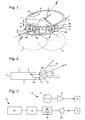
- Fig. 1 shows a perspective view of a wrist-wearable device, in the present case a wrist watch.
- the device comprises an outer housing 1 with a back cover 3 and a front cover 4, in the present case a glass for covering a dial with hands 6, 7 and an electronic display 20.
- a circumferential wall 2 lies between the back cover 3 and the front cover 4 and completes the housing 1.
- This wall 2 is shown as being substantially perpendicular to the front cover 4 and the back cover 3, but a toroidal or rounded shape or any other shape known in watch design is possible.
- the back cover 3 and the front cover 4 are shown as being circular, but they may also be oval or rectangular with or without rounded edges without departing from the scope of the present invention.
- the device shown in Fig. 1 comprises two slot antennas 8, 9, each of them comprising a block-shaped case 8b, 9b and a slot 8a, 9a.
- the cases 8b, 9b are either made of metal or of another material having a metallized inner surface and form a cavity for the slot antennas 8, 9.
- This cavity can be filled with a dielectric material having a high dielectric constant and a low dielectric loss such as Teflon®, a dielectric ceramic material or an appropriate resin.
- Cavity backed slot antennas are known in the art and their function principle will thus not be discussed here. It should be noted, however, that the minimum slot length which is required depends on the wavelength of the radar signal, the permittivity of the dielectric filling material and the shape of the slot.
- the slot length as much as possible so that the height e (cf. Fig. 1 ) of the wrist wearable device can be reduced.
- the shape of the slot may be adapted. It is possible, for example, to use a slot comprising a vertical main slot as shown in the figures and to provide it with additional slot structures which are perpendicular to this main slot, i.e. parallel to the front cover 4 and back cover 3.
- Both cases 8b, 9b have an outer face 8c, 9c which coincides with the circumferential wall 2 of the housing, the slots 8a, 9a being formed in said outer face, respectively.
- the outer faces 8c, 9c are metallized or made of metal and form an antenna surface together with adjacent metal plates 8d, 9d, as it will be explained below.
- the slots 8a, 9a are both oriented in a direction perpendicular to the back cover 3 and to the front cover 4 and are thus parallel to each other.
- one of the slots 8a, 9a may be slightly tilted with respect to the other slot 9a, 8a, and would in this case not be exactly perpendicular to back cover 3 and front cover 4.
- the slots 8a, 9a could be arranged such that the angle between the front cover 4 and the slots 8a, 9a is smaller than 90°. In this case the radiation is directed away from the user's wrist.
- the length of the slot 8a, 9a is determined by different factors, but it will normally be only slightly inferior to the height e of the circumferential wall 2 as shown in Fig. 2 .
- the housing 1 and in particular the wall 2 are made of a plastic material.
- the two cases 8b, 9b of the slot antennas 8, 9 are not directly adjacent, but are arranged at a certain distance d and are thus electrically insulated from each other.
- the example is not limited to devices having plastic housings, however, and the housing 1 can be completely made of metal or comprise metallic parts.
- the circumferential wall 2 is made of an electrically conducting material, a high impedance portion will be provided in the wall 2 between the outer surfaces 8c, 9c. Such a high impedance portion avoids a coupling of the two antennas via surface waves.
- a simple solution would be a plastic insert or a plastic element applied to the surface of the circumferential wall 2 between the two slot antennas 8, 9.
- one can also use appropriate geometrical structures formed in the metal wall 2 such as photonic bandgap structures.
- two metal plates 8d, 9d are applied to the circumferential wall 2 on the left, respectively on the right, of each of the outer surfaces 8c, 9c of the antennas 8, 9.
- the electrically conducting surface of these metal plates 8d, 9d forms a continuous antenna surface together with the respective outer surface 8c, 9c of the slot antenna 8, 9, and the radiation pattern is improved thereby.
- the wall 2 itself is made of an etectrically conducting material such as stainless steel or another metal according to the invention. In such a case parts of the housing 1, in particular parts of the wall 2, can directly be part of the antenna surface.
- the horizontal radiation pattern is denoted with the reference numerals 10, 11 in Fig. 1 .
- the beam width ⁇ of the horizontal pattern (cf. Fig. 1 ) will be above 150°, preferably around 180° or higher, if the size of the outer surfaces 8c, 9c respectively the size of the metal plates 9c, 9d are chosen appropriately. Appropriate distance between the two slot antennas 8, 9, has to be selected to achieve the required value of antenna decoupling.
- the housing 1 is provided with a shielding element 5 lying in the plane of the back cover 3 and protruding from the wall 2 below the slot antennas 8, 9 and below the segment of wall 2 lying between them.
- a shielding element 5 lying in the plane of the back cover 3 and protruding from the wall 2 below the slot antennas 8, 9 and below the segment of wall 2 lying between them.
- the effects of this shielding become clear when looking at Fig. 2 which shows a cut along the axis II-II in Fig. 1 .
- the shielding 5 tilts the main beam directivity direction 13 with respect to the plane of the back cover 3, the tilting angle being denoted as ⁇ in Fig. 2 .
- the vertical radiation pattern obtained is shown in Fig. 2 . and denoted with the reference numeral 12.
- the beam width ⁇ of the vertical pattern 12 can reach up to
- Fig. 3 is a block diagram showing the electronic components necessary for the implementation of a radar speedometer in the device shown in Figs. 1 and 2 .
- a transmission chain 14 associated to a first slot antenna 8 comprises a radar transmitter 17 emitting a radar signal which is amplified by an amplifier 16. The amplified radar signal will be emitted via the slot antenna 8.
- the second slot antenna 9 is part of a reception chain 15 and is connected to a signal processing unit 19 via a receiver 18 and an amplifier 16' amplifying the signal received by the antenna 9.
- the signal processing unit 19 calculates a speed of the user wearing the device shown in Fig. 1 using an appropriate algorithm. Based on the speed, the signal processing unit may also calculate the distance covered by the user. The speed and/or the distance covered can then be shown by the display 20 which is integrated into the device.
Landscapes
- Engineering & Computer Science (AREA)
- Radar, Positioning & Navigation (AREA)
- Remote Sensing (AREA)
- Computer Networks & Wireless Communication (AREA)
- Physics & Mathematics (AREA)
- General Physics & Mathematics (AREA)
- Details Of Aerials (AREA)
- Support Of Aerials (AREA)
- Waveguide Aerials (AREA)
Claims (12)
- Am Handgelenk tragbare Vorrichtung, die ein Außengehäuse (1) mit einer hinteren Abdeckung (3), einer zu der hinteren Abdeckung (3) parallelen vorderen Abdeckung (4) und einer Umfangswand (2) dazwischen umfasst, wobei die Wand zu der hinteren Abdeckung (3) und zu der vorderen Abdeckung (4) senkrecht ist und aus einem elektrisch leitenden Material hergestellt ist, wobei die Vorrichtung ferner zwei Schlitzantennen (8, 9) umfasst, die elektromagnetische Signale senden und empfangen können, wobei jede Schlitzantenne (8, 9) einen Kasten (8b, 9b) mit elektrisch leitenden inneren Oberflächen umfasst, der in das Gehäuse (1) eingepasst ist, wobei der Kasten (8b, 9b) auf einer Seite durch eine äußere Fläche (8c, 9c) begrenzt ist, die im Wesentlichen in einer gemeinsamen Ebene mit der Wand (2) des Gehäuses (1) liegt, wobei ein Schlitz (8a, 9a) in der äußeren Fläche (8c, 9c) des Kastens (8b, 9b) ausgebildet ist, wodurch der Innenraum des Kastens einen Hohlraum der Schlitzantenne (8, 9) bildet, wobei ein Abschnitt mit hoher Impedanz in der Umfangswand (2) zwischen den äußeren Flächen (8c, 9c) der beiden Gehäuse (8b, 9b) vorgesehen ist und wobei sich einer der Schlitze im Wesentlichen in einer Richtung senkrecht zu der hinteren Abdeckung (3) und der vorderen Abdeckung (4) erstreckt.
- Vorrichtung nach Anspruch 1, dadurch gekennzeichnet, dass der Hochimpedanzabschnitt einen Abschnitt aufweist, der aus einem elektrisch isolierenden Material oder aus einer geometrischen Struktur, die eine Oberflächen-kopplung vermeidet, hergestellt ist.
- Vorrichtung nach einem der vorhergehenden Ansprüche, dadurch gekennzeichnet, dass der Kasten (8b, 9b) im Wesentlichen den gesamten Raum in einer Richtung von der hinteren Abdeckung (3) zu der vorderen Abdeckung (4) belegt.
- Vorrichtung nach einem der vorhergehenden Ansprüche, dadurch gekennzeichnet, dass sie ferner ein Abschirmelement (5) umfasst, das in der Ebene der hinteren Abdeckung (3) liegt und von der Wand (2) in einem Bereich unterhalb der Schlitzantenne (8, 9) vorsteht.
- Vorrichtung nach einem der vorhergehenden Ansprüche, dadurch gekennzeichnet, dass das äußere Gehäuse (1) wenigstens teilweise aus einem leitenden Material, insbesondere aus Metall hergestellt ist.
- Vorrichtung nach einem der Ansprüche 1 bis 4, dadurch gekennzeichnet, dass die hintere Abdeckung (3) aus einem nicht leitenden Material, ins-besondere Kunststoff hergestellt ist.
- Vorrichtung nach Anspruch 6, dadurch gekennzeichnet, dass sie wenigstens eine elektrisch leitende Oberfläche (8d, 9d) auf der Umfangswand (2) aufweist, wobei die elektrisch leitende Oberfläche (8d, 9d) zusammen mit einer benachbarten äußeren Oberfläche (8c, 9c) der Schlitzantenne (8, 9) eine ununterbrochene Antennenoberfläche bildet.
- Vorrichtung nach einem der Ansprüche 1 bis 7, dadurch gekennzeichnet, dass der Schlitz (8a) der ersten Schlitzantenne (8) in Bezug auf den Schlitz (9a) der zweiten Schlitzantenne (9) geneigt ist.
- Vorrichtung nach einem der Ansprüche 1 bis 8, dadurch gekennzeichnet, dass sie ferner einen Sender (17), der ein Radarsignal erzeugt und mit einer ersten Schlitzantenne (8) verbunden ist, und einen Empfänger (18), der mit der zweiten Schlitzantenne (9) verbunden ist, umfasst, wobei der Ausgang des Empfängers zu einer Signalverarbeitungseinheit (19) gesendet wird.
- Vorrichtung nach Anspruch 9, dadurch gekennzeichnet, dass die Signalverarbeitungseinheit (19) dazu ausgelegt ist, unter Verwendung von Signalen, die von der zweiten Schlitzantenne (9) aufgefangen werden, eine Geschwindigkeit und/oder eine Strecke, die von einer Person, die die am Handgelenk tragbare Vorrichtung trägt, zurückgelegt wird, zu berechnen.
- Vorrichtung nach einem der vorhergehenden Ansprüche, dadurch gekennzeichnet, dass sie ferner eine Signalverarbeitungseinheit (19), die dazu ausgelegt ist, eine Geschwindigkeit eines Anwenders, der die Vorrichtung trägt, zu berechnen, und Anzeigemittel (20), die dazu ausgelegt sind, die Geschwindigkeit anzuzeigen, umfasst.
- Vorrichtung nach Anspruch 11, dadurch gekennzeichnet, dass die Signalverarbeitungseinheit (19) ferner dazu ausgelegt ist, eine Strecke zu berechnen, die vom Anwender, der die Vorrichtung trägt, zurückgelegt wird, wobei die Anzeigemittel (20) dazu ausgelegt sind, die Geschwindigkeit und die zurückgelegte Strecke anzuzeigen.
Priority Applications (7)
| Application Number | Priority Date | Filing Date | Title |
|---|---|---|---|
| AT08166960T ATE544195T1 (de) | 2008-10-17 | 2008-10-17 | Am handgelenk tragbare vorrichtung mit einer antenne |
| EP08166960A EP2178158B1 (de) | 2008-10-17 | 2008-10-17 | Am Handgelenk tragbare Vorrichtung mit einer Antenne |
| PCT/EP2009/063428 WO2010043656A1 (en) | 2008-10-17 | 2009-10-14 | Wrist-wearable device comprising an antenna |
| JP2011531481A JP5330522B2 (ja) | 2008-10-17 | 2009-10-14 | アンテナ付き手首装着装置 |
| US13/121,575 US8833665B2 (en) | 2008-10-17 | 2009-10-14 | Wrist-wearable device comprising an antenna |
| HK12102274.9A HK1162085B (en) | 2008-10-17 | 2009-10-14 | Wrist-wearable device comprising an antenna |
| CN200980141042.4A CN102187516B (zh) | 2008-10-17 | 2009-10-14 | 包括天线的腕佩设备 |
Applications Claiming Priority (1)
| Application Number | Priority Date | Filing Date | Title |
|---|---|---|---|
| EP08166960A EP2178158B1 (de) | 2008-10-17 | 2008-10-17 | Am Handgelenk tragbare Vorrichtung mit einer Antenne |
Publications (2)
| Publication Number | Publication Date |
|---|---|
| EP2178158A1 EP2178158A1 (de) | 2010-04-21 |
| EP2178158B1 true EP2178158B1 (de) | 2012-02-01 |
Family
ID=40456747
Family Applications (1)
| Application Number | Title | Priority Date | Filing Date |
|---|---|---|---|
| EP08166960A Active EP2178158B1 (de) | 2008-10-17 | 2008-10-17 | Am Handgelenk tragbare Vorrichtung mit einer Antenne |
Country Status (6)
| Country | Link |
|---|---|
| US (1) | US8833665B2 (de) |
| EP (1) | EP2178158B1 (de) |
| JP (1) | JP5330522B2 (de) |
| CN (1) | CN102187516B (de) |
| AT (1) | ATE544195T1 (de) |
| WO (1) | WO2010043656A1 (de) |
Families Citing this family (20)
| Publication number | Priority date | Publication date | Assignee | Title |
|---|---|---|---|---|
| US8896487B2 (en) * | 2009-07-09 | 2014-11-25 | Apple Inc. | Cavity antennas for electronic devices |
| JP5896060B2 (ja) * | 2010-11-12 | 2016-03-30 | セイコーエプソン株式会社 | アンテナ内蔵式電子時計 |
| CN102694230B (zh) * | 2012-04-27 | 2016-12-14 | 深圳光启创新技术有限公司 | 腕表天线及其制造方法、实时通讯腕表 |
| ITTV20120130A1 (it) * | 2012-07-13 | 2014-01-14 | I M Spa | "cassa di dispositivo da polso di interconnessione e comunicazione multimediale che integra un'antenna" |
| US9196952B2 (en) * | 2013-03-15 | 2015-11-24 | Qualcomm Incorporated | Multipurpose antenna |
| US9601824B2 (en) | 2014-07-01 | 2017-03-21 | Microsoft Technology Licensing, Llc | Slot antenna integrated into a resonant cavity of an electronic device case |
| US9653786B2 (en) | 2015-06-27 | 2017-05-16 | Intel Corporation | Wearable antenna system |
| TWI575810B (zh) * | 2015-07-20 | 2017-03-21 | 仁寶電腦工業股份有限公司 | 具無線傳輸功能之手錶錶體及其天線結構 |
| US9985341B2 (en) | 2015-08-31 | 2018-05-29 | Microsoft Technology Licensing, Llc | Device antenna for multiband communication |
| CN106486737A (zh) * | 2015-09-02 | 2017-03-08 | 中兴通讯股份有限公司 | 一种手表天线和手表 |
| KR102447757B1 (ko) | 2015-11-06 | 2022-09-27 | 삼성전자주식회사 | 안테나 장치 및 그것을 포함하는 전자 장치 |
| KR102567892B1 (ko) | 2016-09-05 | 2023-08-17 | 삼성전자주식회사 | 안테나를 포함하는 전자 장치 |
| US10516199B2 (en) | 2017-01-26 | 2019-12-24 | North Inc. | Mobile device with slotted cavity antenna |
| CN110326159B (zh) | 2017-03-27 | 2024-08-23 | 英特尔公司 | 集成到印刷电路板中的天线 |
| US10305174B2 (en) | 2017-04-05 | 2019-05-28 | Futurewei Technologies, Inc. | Dual-polarized, omni-directional, and high-efficiency wearable antenna array |
| CN110048219B (zh) * | 2018-01-17 | 2022-08-16 | 惠州硕贝德无线科技股份有限公司 | 一种集成超宽带5g天线的电子设备 |
| CN112799294A (zh) * | 2021-02-05 | 2021-05-14 | 深圳市爱都科技有限公司 | 一种表体和智能手表 |
| CN116666947A (zh) * | 2022-02-28 | 2023-08-29 | 深圳富泰宏精密工业有限公司 | 天线结构及具有该天线结构的穿戴式装置 |
| CN117154383A (zh) * | 2022-05-24 | 2023-12-01 | 华为技术有限公司 | 一种电子设备 |
| US12300878B2 (en) * | 2022-09-06 | 2025-05-13 | Oura Health Oy | Slot antenna in a wearable device |
Family Cites Families (14)
| Publication number | Priority date | Publication date | Assignee | Title |
|---|---|---|---|---|
| JPS527907B2 (de) * | 1971-11-06 | 1977-03-05 | ||
| JPH0727020B2 (ja) * | 1986-12-25 | 1995-03-29 | 三菱電機株式会社 | レ−ダ−装置 |
| FR2644919B1 (fr) * | 1989-03-21 | 1991-05-31 | Dassault Electronique | Procede et dispositif pour l'aide a la circulation de vehicules terrestres |
| US5589840A (en) * | 1991-11-05 | 1996-12-31 | Seiko Epson Corporation | Wrist-type wireless instrument and antenna apparatus |
| JP3060840B2 (ja) * | 1994-07-19 | 2000-07-10 | セイコーエプソン株式会社 | 腕装着型無線機及びアンテナ装置 |
| DE69424704T2 (de) * | 1993-03-17 | 2000-09-28 | Seiko Epson Corp., Tokio/Tokyo | Antenne und diese enthaltendes Gerät |
| FR2739200B1 (fr) * | 1995-09-26 | 1997-10-31 | Asulab Sa | Piece d'horlogerie comportant une antenne |
| US6307520B1 (en) * | 2000-07-25 | 2001-10-23 | International Business Machines Corporation | Boxed-in slot antenna with space-saving configuration |
| DE10041922A1 (de) * | 2000-08-25 | 2002-03-07 | Armleder Thomas | Armbanduhr |
| CN2448026Y (zh) * | 2000-09-19 | 2001-09-12 | 深圳市乐创意通讯技术有限公司 | 手表传呼机 |
| JP4317791B2 (ja) * | 2004-06-25 | 2009-08-19 | 株式会社国際電気通信基礎技術研究所 | アレーアンテナ |
| US7271774B2 (en) * | 2005-10-21 | 2007-09-18 | Suunto Oy | Electronic wearable device |
| FI124133B (fi) | 2005-10-21 | 2014-03-31 | Suunto Oy | Elektroninen puettava laite |
| US7778118B2 (en) * | 2007-08-28 | 2010-08-17 | Garmin Ltd. | Watch device having touch-bezel user interface |
-
2008
- 2008-10-17 EP EP08166960A patent/EP2178158B1/de active Active
- 2008-10-17 AT AT08166960T patent/ATE544195T1/de active
-
2009
- 2009-10-14 CN CN200980141042.4A patent/CN102187516B/zh active Active
- 2009-10-14 JP JP2011531481A patent/JP5330522B2/ja active Active
- 2009-10-14 WO PCT/EP2009/063428 patent/WO2010043656A1/en not_active Ceased
- 2009-10-14 US US13/121,575 patent/US8833665B2/en active Active
Also Published As
| Publication number | Publication date |
|---|---|
| US8833665B2 (en) | 2014-09-16 |
| ATE544195T1 (de) | 2012-02-15 |
| EP2178158A1 (de) | 2010-04-21 |
| JP2012517718A (ja) | 2012-08-02 |
| HK1162085A1 (en) | 2012-08-17 |
| CN102187516A (zh) | 2011-09-14 |
| WO2010043656A1 (en) | 2010-04-22 |
| US20110234461A1 (en) | 2011-09-29 |
| JP5330522B2 (ja) | 2013-10-30 |
| CN102187516B (zh) | 2014-01-29 |
Similar Documents
| Publication | Publication Date | Title |
|---|---|---|
| EP2178158B1 (de) | Am Handgelenk tragbare Vorrichtung mit einer Antenne | |
| KR102738965B1 (ko) | 안테나 및 그것을 포함하는 전자 장치 | |
| KR102692613B1 (ko) | 안테나를 포함하는 전자 장치 | |
| EP3716403B1 (de) | Antennenmodul und elektronische vorrichtung | |
| KR102028525B1 (ko) | 웨어러블 무선 장치의 결합 다중 대역 안테나 | |
| MY199346A (en) | Antenna module and electronic device comprising same | |
| US20160261032A1 (en) | Wearable electronic device | |
| CN114389031A (zh) | 具有毫米波测距能力的电子设备 | |
| EP2062282A4 (de) | Antennenanordnung für eine elektronische vorrichtung und elektronische vorrichtung damit | |
| WO2020046032A3 (ko) | 안테나 모듈을 포함하는 전자 장치 | |
| KR102695025B1 (ko) | 안테나 및 그것을 포함하는 전자 장치 | |
| CN113170008A (zh) | 包括天线模块的电子装置 | |
| WO2009010724A1 (en) | Antennas | |
| US20200243952A1 (en) | Antenna for Wearable Devices | |
| US11955731B2 (en) | Electronic device including multi-band antenna | |
| TW201914092A (zh) | 行動裝置 | |
| CN210723338U (zh) | 可穿戴设备 | |
| CN112151954B (zh) | 壳体组件、电子设备及壳体组件的介电常数调节方法 | |
| US20180299837A1 (en) | Antenna arrangement for an electronic device and an electronic device including same | |
| CN110915064A (zh) | 一种改进的天线 | |
| HK1162085B (en) | Wrist-wearable device comprising an antenna | |
| US10149636B2 (en) | Relay device for relaying radio frequency signals received from an antenna implanted within a patient's body to another device | |
| JP6782837B2 (ja) | 端末 | |
| JP2006521054A (ja) | 移動無線デバイス用回路装置 | |
| CN115528418B (zh) | 天线单元和电子设备 |
Legal Events
| Date | Code | Title | Description |
|---|---|---|---|
| PUAI | Public reference made under article 153(3) epc to a published international application that has entered the european phase |
Free format text: ORIGINAL CODE: 0009012 |
|
| AK | Designated contracting states |
Kind code of ref document: A1 Designated state(s): AT BE BG CH CY CZ DE DK EE ES FI FR GB GR HR HU IE IS IT LI LT LU LV MC MT NL NO PL PT RO SE SI SK TR |
|
| AX | Request for extension of the european patent |
Extension state: AL BA MK RS |
|
| 17P | Request for examination filed |
Effective date: 20101021 |
|
| 17Q | First examination report despatched |
Effective date: 20101115 |
|
| AKX | Designation fees paid |
Designated state(s): AT BE BG CH CY CZ DE DK EE ES FI FR GB GR HR HU IE IS IT LI LT LU LV MC MT NL NO PL PT RO SE SI SK TR |
|
| GRAP | Despatch of communication of intention to grant a patent |
Free format text: ORIGINAL CODE: EPIDOSNIGR1 |
|
| GRAS | Grant fee paid |
Free format text: ORIGINAL CODE: EPIDOSNIGR3 |
|
| GRAA | (expected) grant |
Free format text: ORIGINAL CODE: 0009210 |
|
| AK | Designated contracting states |
Kind code of ref document: B1 Designated state(s): AT BE BG CH CY CZ DE DK EE ES FI FR GB GR HR HU IE IS IT LI LT LU LV MC MT NL NO PL PT RO SE SI SK TR |
|
| REG | Reference to a national code |
Ref country code: GB Ref legal event code: FG4D |
|
| REG | Reference to a national code |
Ref country code: CH Ref legal event code: NV Representative=s name: ICB INGENIEURS CONSEILS EN BREVETS SA Ref country code: CH Ref legal event code: EP Ref country code: AT Ref legal event code: REF Ref document number: 544195 Country of ref document: AT Kind code of ref document: T Effective date: 20120215 |
|
| REG | Reference to a national code |
Ref country code: DE Ref legal event code: R096 Ref document number: 602008013043 Country of ref document: DE Effective date: 20120329 |
|
| REG | Reference to a national code |
Ref country code: NL Ref legal event code: VDEP Effective date: 20120201 |
|
| LTIE | Lt: invalidation of european patent or patent extension |
Effective date: 20120201 |
|
| PG25 | Lapsed in a contracting state [announced via postgrant information from national office to epo] |
Ref country code: NO Free format text: LAPSE BECAUSE OF FAILURE TO SUBMIT A TRANSLATION OF THE DESCRIPTION OR TO PAY THE FEE WITHIN THE PRESCRIBED TIME-LIMIT Effective date: 20120501 Ref country code: IS Free format text: LAPSE BECAUSE OF FAILURE TO SUBMIT A TRANSLATION OF THE DESCRIPTION OR TO PAY THE FEE WITHIN THE PRESCRIBED TIME-LIMIT Effective date: 20120601 Ref country code: HR Free format text: LAPSE BECAUSE OF FAILURE TO SUBMIT A TRANSLATION OF THE DESCRIPTION OR TO PAY THE FEE WITHIN THE PRESCRIBED TIME-LIMIT Effective date: 20120201 Ref country code: NL Free format text: LAPSE BECAUSE OF FAILURE TO SUBMIT A TRANSLATION OF THE DESCRIPTION OR TO PAY THE FEE WITHIN THE PRESCRIBED TIME-LIMIT Effective date: 20120201 Ref country code: LT Free format text: LAPSE BECAUSE OF FAILURE TO SUBMIT A TRANSLATION OF THE DESCRIPTION OR TO PAY THE FEE WITHIN THE PRESCRIBED TIME-LIMIT Effective date: 20120201 |
|
| PG25 | Lapsed in a contracting state [announced via postgrant information from national office to epo] |
Ref country code: PT Free format text: LAPSE BECAUSE OF FAILURE TO SUBMIT A TRANSLATION OF THE DESCRIPTION OR TO PAY THE FEE WITHIN THE PRESCRIBED TIME-LIMIT Effective date: 20120601 Ref country code: PL Free format text: LAPSE BECAUSE OF FAILURE TO SUBMIT A TRANSLATION OF THE DESCRIPTION OR TO PAY THE FEE WITHIN THE PRESCRIBED TIME-LIMIT Effective date: 20120201 Ref country code: BE Free format text: LAPSE BECAUSE OF FAILURE TO SUBMIT A TRANSLATION OF THE DESCRIPTION OR TO PAY THE FEE WITHIN THE PRESCRIBED TIME-LIMIT Effective date: 20120201 Ref country code: GR Free format text: LAPSE BECAUSE OF FAILURE TO SUBMIT A TRANSLATION OF THE DESCRIPTION OR TO PAY THE FEE WITHIN THE PRESCRIBED TIME-LIMIT Effective date: 20120502 Ref country code: FI Free format text: LAPSE BECAUSE OF FAILURE TO SUBMIT A TRANSLATION OF THE DESCRIPTION OR TO PAY THE FEE WITHIN THE PRESCRIBED TIME-LIMIT Effective date: 20120201 Ref country code: LV Free format text: LAPSE BECAUSE OF FAILURE TO SUBMIT A TRANSLATION OF THE DESCRIPTION OR TO PAY THE FEE WITHIN THE PRESCRIBED TIME-LIMIT Effective date: 20120201 |
|
| REG | Reference to a national code |
Ref country code: AT Ref legal event code: MK05 Ref document number: 544195 Country of ref document: AT Kind code of ref document: T Effective date: 20120201 |
|
| PG25 | Lapsed in a contracting state [announced via postgrant information from national office to epo] |
Ref country code: CY Free format text: LAPSE BECAUSE OF FAILURE TO SUBMIT A TRANSLATION OF THE DESCRIPTION OR TO PAY THE FEE WITHIN THE PRESCRIBED TIME-LIMIT Effective date: 20120201 |
|
| PG25 | Lapsed in a contracting state [announced via postgrant information from national office to epo] |
Ref country code: CZ Free format text: LAPSE BECAUSE OF FAILURE TO SUBMIT A TRANSLATION OF THE DESCRIPTION OR TO PAY THE FEE WITHIN THE PRESCRIBED TIME-LIMIT Effective date: 20120201 Ref country code: RO Free format text: LAPSE BECAUSE OF FAILURE TO SUBMIT A TRANSLATION OF THE DESCRIPTION OR TO PAY THE FEE WITHIN THE PRESCRIBED TIME-LIMIT Effective date: 20120201 Ref country code: SI Free format text: LAPSE BECAUSE OF FAILURE TO SUBMIT A TRANSLATION OF THE DESCRIPTION OR TO PAY THE FEE WITHIN THE PRESCRIBED TIME-LIMIT Effective date: 20120201 Ref country code: EE Free format text: LAPSE BECAUSE OF FAILURE TO SUBMIT A TRANSLATION OF THE DESCRIPTION OR TO PAY THE FEE WITHIN THE PRESCRIBED TIME-LIMIT Effective date: 20120201 Ref country code: SE Free format text: LAPSE BECAUSE OF FAILURE TO SUBMIT A TRANSLATION OF THE DESCRIPTION OR TO PAY THE FEE WITHIN THE PRESCRIBED TIME-LIMIT Effective date: 20120201 Ref country code: DK Free format text: LAPSE BECAUSE OF FAILURE TO SUBMIT A TRANSLATION OF THE DESCRIPTION OR TO PAY THE FEE WITHIN THE PRESCRIBED TIME-LIMIT Effective date: 20120201 |
|
| PG25 | Lapsed in a contracting state [announced via postgrant information from national office to epo] |
Ref country code: IT Free format text: LAPSE BECAUSE OF FAILURE TO SUBMIT A TRANSLATION OF THE DESCRIPTION OR TO PAY THE FEE WITHIN THE PRESCRIBED TIME-LIMIT Effective date: 20120201 Ref country code: SK Free format text: LAPSE BECAUSE OF FAILURE TO SUBMIT A TRANSLATION OF THE DESCRIPTION OR TO PAY THE FEE WITHIN THE PRESCRIBED TIME-LIMIT Effective date: 20120201 |
|
| PLBE | No opposition filed within time limit |
Free format text: ORIGINAL CODE: 0009261 |
|
| STAA | Information on the status of an ep patent application or granted ep patent |
Free format text: STATUS: NO OPPOSITION FILED WITHIN TIME LIMIT |
|
| 26N | No opposition filed |
Effective date: 20121105 |
|
| PG25 | Lapsed in a contracting state [announced via postgrant information from national office to epo] |
Ref country code: AT Free format text: LAPSE BECAUSE OF FAILURE TO SUBMIT A TRANSLATION OF THE DESCRIPTION OR TO PAY THE FEE WITHIN THE PRESCRIBED TIME-LIMIT Effective date: 20120201 |
|
| REG | Reference to a national code |
Ref country code: DE Ref legal event code: R097 Ref document number: 602008013043 Country of ref document: DE Effective date: 20121105 |
|
| PG25 | Lapsed in a contracting state [announced via postgrant information from national office to epo] |
Ref country code: ES Free format text: LAPSE BECAUSE OF FAILURE TO SUBMIT A TRANSLATION OF THE DESCRIPTION OR TO PAY THE FEE WITHIN THE PRESCRIBED TIME-LIMIT Effective date: 20120512 |
|
| PG25 | Lapsed in a contracting state [announced via postgrant information from national office to epo] |
Ref country code: MC Free format text: LAPSE BECAUSE OF NON-PAYMENT OF DUE FEES Effective date: 20121031 |
|
| GBPC | Gb: european patent ceased through non-payment of renewal fee |
Effective date: 20121017 |
|
| REG | Reference to a national code |
Ref country code: IE Ref legal event code: MM4A |
|
| PG25 | Lapsed in a contracting state [announced via postgrant information from national office to epo] |
Ref country code: BG Free format text: LAPSE BECAUSE OF FAILURE TO SUBMIT A TRANSLATION OF THE DESCRIPTION OR TO PAY THE FEE WITHIN THE PRESCRIBED TIME-LIMIT Effective date: 20120501 Ref country code: GB Free format text: LAPSE BECAUSE OF NON-PAYMENT OF DUE FEES Effective date: 20121017 Ref country code: IE Free format text: LAPSE BECAUSE OF NON-PAYMENT OF DUE FEES Effective date: 20121017 |
|
| PG25 | Lapsed in a contracting state [announced via postgrant information from national office to epo] |
Ref country code: MT Free format text: LAPSE BECAUSE OF FAILURE TO SUBMIT A TRANSLATION OF THE DESCRIPTION OR TO PAY THE FEE WITHIN THE PRESCRIBED TIME-LIMIT Effective date: 20120201 |
|
| PG25 | Lapsed in a contracting state [announced via postgrant information from national office to epo] |
Ref country code: TR Free format text: LAPSE BECAUSE OF FAILURE TO SUBMIT A TRANSLATION OF THE DESCRIPTION OR TO PAY THE FEE WITHIN THE PRESCRIBED TIME-LIMIT Effective date: 20120201 |
|
| PG25 | Lapsed in a contracting state [announced via postgrant information from national office to epo] |
Ref country code: LU Free format text: LAPSE BECAUSE OF NON-PAYMENT OF DUE FEES Effective date: 20121017 |
|
| PG25 | Lapsed in a contracting state [announced via postgrant information from national office to epo] |
Ref country code: HU Free format text: LAPSE BECAUSE OF FAILURE TO SUBMIT A TRANSLATION OF THE DESCRIPTION OR TO PAY THE FEE WITHIN THE PRESCRIBED TIME-LIMIT Effective date: 20081017 |
|
| REG | Reference to a national code |
Ref country code: FR Ref legal event code: PLFP Year of fee payment: 9 |
|
| REG | Reference to a national code |
Ref country code: FR Ref legal event code: PLFP Year of fee payment: 10 |
|
| PGFP | Annual fee paid to national office [announced via postgrant information from national office to epo] |
Ref country code: FR Payment date: 20170921 Year of fee payment: 10 |
|
| PGFP | Annual fee paid to national office [announced via postgrant information from national office to epo] |
Ref country code: DE Payment date: 20170920 Year of fee payment: 10 |
|
| REG | Reference to a national code |
Ref country code: DE Ref legal event code: R119 Ref document number: 602008013043 Country of ref document: DE |
|
| PG25 | Lapsed in a contracting state [announced via postgrant information from national office to epo] |
Ref country code: DE Free format text: LAPSE BECAUSE OF NON-PAYMENT OF DUE FEES Effective date: 20190501 |
|
| PG25 | Lapsed in a contracting state [announced via postgrant information from national office to epo] |
Ref country code: FR Free format text: LAPSE BECAUSE OF NON-PAYMENT OF DUE FEES Effective date: 20181031 |
|
| P01 | Opt-out of the competence of the unified patent court (upc) registered |
Effective date: 20230701 |
|
| REG | Reference to a national code |
Ref country code: CH Ref legal event code: U11 Free format text: ST27 STATUS EVENT CODE: U-0-0-U10-U11 (AS PROVIDED BY THE NATIONAL OFFICE) Effective date: 20251101 |
|
| PGFP | Annual fee paid to national office [announced via postgrant information from national office to epo] |
Ref country code: CH Payment date: 20251101 Year of fee payment: 18 |