EP2178337A1 - Appareil ménager doté d'un système de chauffage et procédé de commande de l'énergie de chauffage dans un appareil ménager - Google Patents
Appareil ménager doté d'un système de chauffage et procédé de commande de l'énergie de chauffage dans un appareil ménager Download PDFInfo
- Publication number
- EP2178337A1 EP2178337A1 EP08018234A EP08018234A EP2178337A1 EP 2178337 A1 EP2178337 A1 EP 2178337A1 EP 08018234 A EP08018234 A EP 08018234A EP 08018234 A EP08018234 A EP 08018234A EP 2178337 A1 EP2178337 A1 EP 2178337A1
- Authority
- EP
- European Patent Office
- Prior art keywords
- heating
- alternating current
- wave
- control signal
- current
- Prior art date
- Legal status (The legal status is an assumption and is not a legal conclusion. Google has not performed a legal analysis and makes no representation as to the accuracy of the status listed.)
- Withdrawn
Links
Images


Classifications
-
- H—ELECTRICITY
- H05—ELECTRIC TECHNIQUES NOT OTHERWISE PROVIDED FOR
- H05B—ELECTRIC HEATING; ELECTRIC LIGHT SOURCES NOT OTHERWISE PROVIDED FOR; CIRCUIT ARRANGEMENTS FOR ELECTRIC LIGHT SOURCES, IN GENERAL
- H05B1/00—Details of electric heating devices
- H05B1/02—Automatic switching arrangements specially adapted to apparatus ; Control of heating devices
- H05B1/0227—Applications
- H05B1/0252—Domestic applications
Definitions
- the invention relates to a household appliance having a heating system which is operable with an alternating current having an alternating current and the at least one at least one heating element comprehensive heating circuit and a control device with which at least one control signal can be output comprises, depending on the control signal by the at least a heating element actually emitted heating energy is controllable.
- the invention relates to a method for controlling the energy supplied by an AC operated heating circuit of a household appliance heat energy with a heating element, the actual output heat energy is controlled during operation.
- Domestic appliance heating systems are known in the art and are widely used to heat domestic appliance flowing media, such as air or water, to a predetermined target temperature range. It is also possible with these heating systems to heat stationary media or to keep their temperature within the target temperature range.
- the household appliance can fulfill the task set him, for example, the drying of clothing, the cleaning of dishes or the brewing of coffee, optimally.
- the heating systems In order to build the heating systems with few components and thus inexpensive, they are often operated on an AC operating voltage or AC, as it is provided by the usual utility grids available.
- the AC operating voltage is present as a sinusoidal voltage with a nominal value of 230 V at 50 Hz.
- the length of one of a positive and a negative half wave period of the alternating current is 20 ms here.
- common heating systems have several heating circuits, which are optionally supplied with operating energy. If the operating energy, for example, normally passed through only one heating circuit, the Medium heated on average to a temperature in a low target temperature range. The heating circuit converts the alternating current into a predetermined maximum heating energy.
- a further heating circuit which may be connected in parallel, for example, with the first heating circuit, received via a switch in the operating power flow, so that now both heating circuits each give the predetermined maximum heating energy, ie the summed heating energy.
- the medium may be heated to a temperature within a high target temperature range.
- the amplitude of the alternating current supplied to the at least two heating circuits connected in parallel to one another is proportionally increased when the increased heating energy is output in comparison to the circuit with only one active heating circuit.
- a disadvantage of these widely used devices is that additional heating circuits are added to the heating system to increase the heat output, which remain unused when a heating energy that is less than the maximum heating energy.
- the additional heating circuits require space and are therefore often spaced from the originally integrated in the heating system and active in operation heating circuits. If the additional heating circuits are not active, the medium is heated only locally in the area of the active heating circuits.
- the medium is heated on average with half the maximum heating energy.
- the heating energy distribution is locally very different, since the medium is heated locally only by individual heating circuits.
- the active heating elements are operated with their maximum heating energy or their maximum heating power and heat the surrounding medium accordingly strong. In the area of the non-active heating elements, the medium is not heated appreciably.
- the mixing is insufficient or if the medium can not be mixed, there are limited areas in the medium which are either above or below the desired temperature range. If the actual temperature of the medium deviates absolutely, ie not only on average, from the specified target temperature, then under certain circumstances this may be the case Home appliance no longer fulfill its task. In some cases, the items to be processed by the household appliance may be damaged. For example, too high air temperatures in clothes dryers can damage the laundry to be dried so that, for example, cotton garments can be damaged if overheated during the drying process.
- the object is achieved in that in the at least one heating integrated with the at least one heating element series Wellenmoduliervoriques is integrated, which is supplied via a control line, the control signal and by the function of the control signal at least a portion of AC period of the guided to the heating element as a heating current alternating current can be faded out.
- the object is achieved in that for controlling the heating energy portions of the converted in heating energy alternating current are hidden in front of the heating element.
- the solution according to the invention is structurally simple and has the advantage that no heating circuits have to be switched on or off to control the converted and discharged heating energy. With such a household appliance designed or functioning, the actual heating energy can be completely controlled by the at least one heating circuit. All heating elements of the at least one heating circuit uniformly heat the medium, regardless of the actual heating energy. Local, deviating from the target temperature range areas in the medium are at least greatly reduced, so that, for example, in a tumble dryer to be dried laundry undergoes no spatially limited superheated air currents through which the clothing is damaged. If the heating system is designed with a plurality of heating circuits, all heating circuits that are less than the maximum heating power can also be involved in heating the medium.
- the heating system may comprise at least one further, second heating circuit which includes a second wave-modulating device and at least one further heating element connected in series with the wave-modulating device.
- This additional heating circuit can be connected in parallel with the first heating circuit to form a heating circuit group.
- at least a portion of the alternating current period of the alternating current conducted as a heating current to the further heating element as a function of the control signal can be faded out by the second wave modulating device.
- the heating circuit group may have an even or an odd number of heating circuits.
- a heating circuit group with an even number of parallel heating circuits has proved to be particularly advantageous.
- the heating system may comprise a further Wellenmoduliervoriques, which is connected upstream of the heating circuit group in series. With this further wave-modulating device, the heat energy emitted can be controllable for the entire heating circuit group.
- At least one of the Wellenmoduliervoriquesen may be formed as a half-wave blocking device and having a control signal dependent electrical conductivity, so in response to the control signal do not pass a selected of two half-waves each an AC period via a Walkerstroman gleich to the heating element and the other half-wave to the heating element. The other half-wave is hidden or blocked.
- the actual heating energy corresponds to half the maximum heating energy. If the half-wave blocking device allows both shafts to pass, the alternating current is conducted completely as a heating current through the heating element and converted into the maximum heating energy. This actual heating energy can be delivered via the heating element directly or indirectly to the medium to be heated.
- the heating power consumed by the heating system can greatly deviate from the sine wave of the mains voltage at half the heating energy.
- the heating system may have a suppression device.
- this suppression device is possibly expensive to implement and expensive, so that it is not suitable for all household appliances.
- the heating system may have at least two heating circuits with a first and a second Wellenmoduliervoriques, both of which are designed as half-wave blocking devices and connected in series with at least one heating element.
- the two heating circuits can be interconnected in particular parallel to the heating circuit group.
- the half-wave of the alternating current period which is not passed through the first heating circuit, can flow through the heating current output of the second half-wave blocking device and be converted here separately into heating energy.
- both half-waves of the alternating current period can be separately faded out as a function of the control signal;
- one half-wave blocking device for example, the first half-wave and with the other half-wave blocking the second half-wave.
- Both half-waves of the sinusoidal alternating current are thus alternately passed as a heating current through each one of the heating circuits.
- the sinusoidal alternating current flows completely through the heating circuit group and is used evenly to generate the heating energy, even if the heating system is operated with less than the maximum heating energy. All heating circuits contribute evenly to the heating of the medium.
- noise is reduced and can be negligible.
- the control and in particular the reduction of the heating energy causes only low electromagnetic interference, since the heating currents passed through the heating circuit group in total substantially correspond to the complete alternating current.
- the electromagnetic compatibility is good; On a possibly complex suppression device can be dispensed with.
- the heating elements of the heating circuits behave electrically the same in each case, the disturbances are negligible.
- the sum of the heating currents essentially corresponds to a symmetrical and sinusoidal flow of public utility networks.
- a domestic appliance with a heating system which can be operated with an alternating current and has an even number of heating circuits connected in parallel to the heating circuit group, wherein the heating circuits each comprise a half-wave blocking device and at least one heating element connected in series, can be regarded as an independent advantageous embodiment.
- the first of two half-waves each an AC period and flow through a second half of the heating circuits the second of two half-waves each an AC period as a heating current.
- the complete sinusoidal alternating current can flow completely through the heating circuit group, regardless of the actual heating energy; Faults are avoided and all heating circuits heat the medium evenly.
- the output in response to the control signal heating energy can either correspond to the maximum heating energy or half of the maximum heating energy.
- a heating circuit group with more than two heating circuits offers the advantage that the heating energy can be released over a larger area. Is the distribution of heating energy, however, an odd Number of heating circuits necessary, the heating elements of the heating circuits, through which one of the half-waves is passed, electrically behave in total equal to the heating elements of the heating circuits through which the other half-wave is passed.
- the heating circuit group may consist of two heating circuit sub-groups, which are connected in parallel with each other.
- the heating circuit sub-groups may consist of several heating circuits, which are interconnected to Schuniknetzen so that the two Schunikteil development behave electrically substantially the same.
- the electrical alternating current resistance of the two heating circuit sub-groups may be the same, so that the heating current in operation flows in terms of amount with the same amplitude through each of the heating circuit sub-groups connected in parallel.
- the half-wave blocking devices may each comprise at least one diode and a switching element, which may be connected in parallel with each other, wherein the electrical conductivity of the switching element may be dependent on the control signal.
- the switching element may for example be an operating element of the household appliance in the form of a purely mechanical switch. When the switch is closed, virtually the full alternating current can flow as heating current through the switch and through the heating element. The maximum heating energy is converted and discharged.
- the diode is short-circuited by the switch and can be seen here as a non-active part of the heating system.
- the switching element is not conductive and shaped, for example, as an open switch
- the alternating current can no longer flow through the switching element, but only through the diodes to the heating element, but each is conductive only for one of the half-waves or only one flow direction of the alternating current , Since only half of the half-waves are conducted to the respective heating elements, these convert half of the maximum heating energy.
- the fading corresponds to the blocking of a current flow which would flow according to the sign of the amplitude of the half-wave of the alternating current or the operating voltage in the reverse direction of the diode.
- the switching element can also be designed as an electromechanical switch, for example in the form of a relay, or as an electronic switch in the form of a transistor circuit or a semiconductor valve, to which at least one of the control signals is supplied by the control device.
- the forward direction of the diodes of a first half of the heating circuits can be aligned opposite to the forward direction of the diodes of a second half of the heating circuits of the heating circuit group.
- this half-wave of the alternating current with the maximum amplitude flows through this diode and its heating element. If another half-wave of the operating voltage is applied later, the current flows in the other direction.
- the first diode blocks and the current flows through the second diode and the heating element connected in series with it.
- the heating circuits are operated alternately with the maximum heating current and briefly record the same maximum power as closed switches. However, this power is absorbed only half as long, so that the heat energy delivered by each of the heating circuits corresponds to half of the maximum heating energy. For 50 Hz supply networks, the heating current flows at half the heating energy 50 times per second for a period of 10 ms through the respective heating element.
- the absolute amplitude of the alternating current flowing to the heating circuit group may depend on the operating state of the heating system. If the maximum heating energy is output by the heating system, the amplitude of the alternating current can be greater and in particular substantially twice as large as the amplitude of the alternating current when half the heat energy is output.
- the switching elements of these heating circuits may have individual and dependent on the at least one control signal switching states.
- the heating energy can be limited locally or controllable as a whole in smaller stages.
- the switching elements of one half of the heating circuits are closed, so that the alternating current can flow completely with both half-waves through the respective heating elements and the switching elements of the second half of the heating circuits switched not conductive, so that only one of the half-waves can flow through the heating elements of these heating circuits, the heating system gives a total of 75% of the maximum heating energy.
- the absorbed heating power in this case is no longer symmetrical and the electromagnetic interference increase with the proportion of different switching elements switched.
- the switching elements of the heating circuit group have common switching states which depend on the at least one control signal, the disturbances are negligible. However, the control of the heating circuits to 75% of the maximum value is not possible here; the switching levels are 100%, 50% and 0% of the maximum energy.
- the switched-off heating circuits or their heating elements can be arranged evenly distributed in a heating area in which the medium is to be heated, or in the vicinity of active heating circuits.
- the wave modulating device may be configured as a full wave blocking device by which alternating current periods of the alternating current conducted as a heating current to the heating element may be repeatedly faded out as a function of the control signal. For example, every third AC period may be substantially completely faded out in response to the control signal.
- the full-wave blocking device may include at least one semiconductor valve and, in a heating period, allow a predetermined number of alternating current periods of the complete alternating current to flow to the at least one heating circuit or group to subsequently block at least one selected alternating current period, ie, a full wave, of the alternating current.
- the recorded heating power deviates here in total from the sinusoidal shape. However, if the heating period is at least two full cycle AC periods and the full AC current outside the periodic heating period is not passed through the heating circuit as a heating current for only one period length, the disturbances will be low.
- control levels may depend on the ratio between the transmitted and the blocked periods.
- control levels 100%, 66%, 50%, 33% and 0% are possible. Again, all heating circuits are equally involved in the heating of the medium.
- the control signal for the full-wave blocking device may be formed, for example, as a periodic rectangular signal whose duty cycle correspond to a full-wave control stage.
- the control signal may be in phase with the operating voltage or current, thereby fading or blocking a full wave having at least one alternating current period.
- the control signal in the heating period above a predetermined threshold and outside the heating period below a predetermined threshold.
- the length of time of the heating period as well as the portion between the heating periods may correspond to an integer multiple of a period of the complete alternating current. The larger the ratio of the heating period to the section between the heating periods, the lower the disturbance and the higher the actual heating energy.
- the heating circuit group can be preceded by an amplitude reduction device, for example in the form of a power amplifier, which as a push-pull output stage with transistors can control the heating power received by the heating system as a function of the at least one control signal.
- a power amplifier which as a push-pull output stage with transistors can control the heating power received by the heating system as a function of the at least one control signal.
- the sinusoidal form of the alternating current is essentially preserved here, so that disturbances possibly caused by this control can be negligible.
- the power amplifier can be integrated in series with the heating circuits or the heating circuit network in the heating system.
- the control signal may here be essentially a direct current or a direct voltage.
- the wave-modulating device is designed as a partial wave blocking device, for example in the form of a phase or section control.
- a portion of at least one of the half cycles of the alternating current period of the alternating current conducted as a heating current to the heating element may be fade out in dependence on the control signal.
- the hidden portion may in particular be shorter than half the AC period and thus last a fraction of the length of the half-wave.
- the partial wave blocking device may comprise a thyristor or a triac to which a pulse-shaped control signal is supplied and which conducts the alternating current only between the pulse and a subsequent or previous reaching of a threshold value of the alternating current amplitude or the operating voltage.
- the heating of media in household appliances in stages or steplessly controlled.
- all heating circuits in the heating system can heat the medium evenly, regardless of the heating energy selected.
- the described heating system can control the output heating energy with a small number of components in at least three stages, all existing heating circuits are active and can heat the medium evenly. Therefore, it is for household appliances that have a uniform. Heating used media need, usable and particularly advantageous in tumble dryers, dishwashers, coffee machines or washing machines used.
- Another advantage of the heating system is that the energy consumption of the heating system can be optimized by the stepped or stepless control of the heating circuits.
- the heat energy delivered can now be selectively controlled without the need to switch on or off complete heating circuits, which also leads to an increased loss of energy due to the possibly required mixing of differently heated media areas.
- the use of the heating system with a tumble dryer wherein the heating system used for the drying of wet laundry air is heated, is advantageous.
- the temperature of the drying air can be tailored to the type of laundry, for example, to the substances, or to the degree of drying.
- the control device can be set by the user of the clothes dryer on the type of clothing, so that the control device can produce, for example, a predetermined and available in the heating system temporal temperature profile for cotton.
- the tumble dryer may also have a loading sensor, a moisture sensor or a weight sensor, which can determine the amount and / or drying state of the laundry to be dried, this information being able to be used to control the heating system of the control device.
- FIG. 1 1 shows a schematic electrical circuit of a heating system 1 with an alternating current source 2 and a heating circuit 3.
- the heating circuit 3 comprises a heating element 4 and a wave-modulating device 5 connected in series with the heating element 4.
- the wave-modulating device 5 becomes an alternating current from the alternating current source 2 via a line 6 fed.
- a line 7 connects a heating current output of the wave modulating device 5 designed as a heating current connection C to the heating element 4, which in turn is connected to the alternating current source 2 via a line 8 and thus closes the circuit of the heating system 1.
- switch 9 can be the circuit of the heating system 1 close or interrupt.
- the switch 9 is shown here open, so that heating energy from the heating system 1 can not be delivered.
- the wave-modulating device 5 has a control connection 10, which can be connected to a control device, not shown here, which can generate a control signal S.
- the wave modulating device 5 changes its electrical conductivity.
- the wave-modulating device 5 the alternating current in response to the control signal S can flow completely from the AC power source 2 to the heating element 4 or each guide at least a portion of a period of the alternating current to the heating element 4.
- FIG. 2 shows a further embodiment, wherein for elements that are in function and structure of the elements of the embodiment of FIG. 1 correspond, the same reference numerals are used. For the sake of brevity we will focus on the differences from the embodiment of FIG. 1 received.
- FIG. 2 shows the heating system 1 of FIG. 1 wherein the wave modulating device 5 is shown in an example circuit as a half-wave blocking device having a diode 11 and a switching element 12 connected in parallel with the diode 11.
- the switching state of the switching element 12 depends on the control signal S. If the switching element 12 is closed, the diode 11 is practically short-circuited. If the switch 9 is also closed, the alternating current of the alternating current source 2 flows substantially completely and exclusively via the switching element 12 to the heating element 4. The heating element 4 now emits a maximum heating energy.
- the diode 11 is connected in series with the heating element 4 and allows either positive or negative half-waves of the alternating current to flow to the heating element 4 when the switch 9 is closed in response to a predetermined blocking direction of the diode 11.
- the heating system 1 is therefore only half of the maximum heating energy in comparison to the closed switching element 12.
- FIGS. 3a and 3b show a further embodiment, wherein for elements that are in function and structure of the elements of the embodiments of the Figures 1 or 2 correspond, the same reference numerals are used. For the sake of brevity, the differences to the embodiments of the Figures 1 and 2 received.
- FIG. 3a schematically shows the time course of the full alternating current Hmax, which flows as a heating current through the Schustroman gleich C when the parallel connected to the diode 11 switching element 12 is closed.
- the complete AC Hmax is represented as a complete sine wave with an amplitude Amax that includes both positive halfwaves H + and negative halfwaves H-.
- the positive and negative half-waves H +, H- extend between the time axis intersecting zero crossings of the full alternating current Hmax.
- the heating current H flows, as in FIG. 3b represented by the heating element 4.
- the amplitude A substantially corresponds to the amplitude Amax of the complete heating current Hmax.
- Negative half-waves H- can not pass the diode 11 up to possible leakage currents. An illustration of the leakage currents or other effects of nonlinear characteristics of the diode 11 will be made here For clarity omitted.
- the diode 11 may also be arranged in the half-wave modulating device 5 so that only negative half-waves H- are conducted through the heating circuit 3 and positive heating waves H + are blocked.
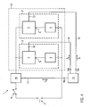
- FIG. 4 shows a further embodiment, wherein for elements that correspond in function and structure to the elements of the embodiments of the previous figures, the same reference numerals are used. For brevity, the differences to the embodiments of the already described figures will be discussed.
- FIG. 4 shows a further embodiment of the heating system 1, wherein the heating system 1 in addition to the heating circuit 3 still another heating circuit 3 'includes.
- the heating circuits 3, 3 ' are connected in parallel with each other to a heating circuit group 15, wherein the third Wellenmoduliervor exercises 14 is connected in series with the heating circuit 15.
- the control device 13 here has three signal outputs 16a, b, c, via the control signals Sa, b, c for the Wellenmoduliervortechniken 5, 5 ', 14 can be output.
- the control signals Sa, b, c are thereby conducted via the lines 17, 18, 19 from the control device 13 to the Wellenmoduliervortechniken 5, 5 ', 14.
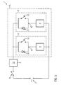
- FIG. 5 shows the embodiment of the FIG. 4 , whereby also here for elements, which in function and structure the elements of the embodiment of the FIG. 4 correspond, the same reference numerals are used. For brevity, the differences to the embodiment of the FIG. 4 received.
- FIG. 5 shows the heating system of FIG. 4 wherein the wave modulating devices 5, 5 'are shown here by way of example as half-wave blocking devices with diodes 11, 11' and switching elements 12, 12 'connected in parallel therewith.
- the diode 11 'of the heating circuit 3' is opposite to the diode 11 of the heating circuit 3 connected.
- the third wave modulating device 14 may be configured, for example, as a partial or full wave blocking device shown connected in series with the heating circuit group 15.
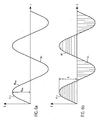
- FIG. 6a again shows the time course of the complete alternating current Hmax shown as a complete sine wave, which includes both positive half-waves H + and negative half-waves H- with the amplitude Amax.
- the complete alternating current Hmax flows both through the heating element 4 and through the heating element 4', which thus deliver the maximum heating energy in the time average.
- FIG. 6b shows the time course of the current flowing through the heating circuits 3, 3 'alternating current H with open switching elements 12, 12'.
- Positive halfwaves H + are here parallel to the time axis t
- negative halfwaves H- are shown hatched perpendicular to the time axis t.
- Both positive half-waves H + and negative half-waves H- have in amplitude the amplitude A, which essentially corresponds to the amplitude Amax of the complete alternating current Hmax, but the amplitude A may deviate absolutely from the amplitude of the complete alternating current Hmax when the switching elements 12, 12 'are closed ,
- Positive half waves H + are only passed through one of the heating circuits 3, 3 '.
- the diode 11 only allows positive half-waves H + to flow through the heating element 4 of the heating circuit 3, and the diode 11 'allows only negative half-waves H- to flow through the heating element 4' of the heating circuit 3 'when the switching element 12' is open.
- the heating elements 4, 4 ' with open switching element 12, 12' so in each case only half of the maximum heating energy from, with a total of the heating circuit 15 of the full alternating current Hmax is passed.
- the third wave modulating device 14 derives the complete alternating current Hmax in this embodiment.
- FIGS. 7a, b and c show a further embodiment, wherein for elements which correspond in function and structure to the elements of the embodiments of the previous figures, the same reference numerals are used. For brevity, the differences to the embodiments of the already described figures will be discussed.
- FIGS. 7a-c illustrate the time course of the heating current H when the third wave modulating device 14 comprises a so-called full-wave blocking device.
- the Figure 7a again shows the time course of the complete alternating current Hmax, where eight alternating current periods are shown here.
- the first heating current period P1 of the heating current H conducted through the heating circuit group 15 FIG. 7b comprises a guided through the heating circuit 3 half-wave H +, which is also hatched here parallel to the time axis t, and a guided through the heating circuit 3 'half-wave H-, which in turn is hatched perpendicular to the time axis t.
- the half-waves H + and H- both have the same amplitude A in amplitude, which corresponds to the amplitude Amax of the complete alternating current Hmax.
- the half-waves H +, H- one of the first period P1 following period P2 of the heating current H reaches the amplitude A.
- the two periods P1 and P2 are passed in dependence on the control signal Sa by the amplitude reduction device 14 to the heating circuit group 15.
- the amplitude A of the heating current is substantially 0; the third wave modulating device 14 suppresses this selected period of the alternating current Hmax and does not flow it as a heating current H to the heating circuit group 15.
- Each three periods P1, P2, P3 form a Walkerstromchro P.
- the output heat energy corresponds to 33% of the maximum heating energy.
- FIG. 7c shows by way of example the control signal Sa, which here has the form of a periodic square wave signal whose amplitude is either 1 or 0.
- the period length Ps of the control signal Sa corresponds to the period length of the heating current packet P.
- the period Ps can also be any natural multiple of the first period P1 of the heating current H or of an alternating current cycle length of the complete alternating current Hmax.
- the control signal Sa is in phase with the complete alternating current Hmax or the operating voltage, not shown here; the phase shift between the control signal Sa and the full alternating current Hmax is substantially equal to zero.
- control signal Sa Over a period corresponding to two-thirds of the period Ps, the control signal Sa has the amplitude of 1, in the remaining third of the period Ps, the amplitude is substantially 0.
- the duty cycle of the control signal Sa is thus two-thirds.
- the heat energy emitted can be controlled in several stages as a function of the control signals Sa, Sb, Sc. If the third wave modulating device 14 passes the complete alternating current Hmax and the switching elements 12, 12 'are closed, the heating system emits 100% of the maximum heating energy. If the third wave modulating device 14 passes only two out of three periods P1, P2, P3 of the complete alternating current Hmax as heating current H to the heating circuit group 15 and if the switching elements 12, 12 'are closed, 66% of the heating energy is available.
- the wave modulating device 14 passes the complete alternating current Hmax and the switching elements 12, 12 'are not turned on, only one of two half-waves H +, H- is conducted to one of the heating elements 4, 4' and only half of the maximum heating energy is passed changed.
- both the first 5 and second 5 'and third 14 wave blocking devices are active and allow only selected portions of the full alternating current Hmax to pass, the heating system generates 33% of the maximum heating energy.
- the switch 9 is open and no heating current H flows through the heating system, 0% of the maximum heating energy is generated.
- FIGS. 8a, b and c a further embodiment, wherein for elements which correspond in function and structure to the elements of the embodiments of the previous figures, the same reference numerals are used. For brevity, the differences to the embodiments of the already described figures will be discussed.
- FIGS. 8 a to c illustrate the time course of the heating current H and the control signal Sa when the third wave modulating device 14 comprises a so-called partial wave blocking device.
- FIG. 8a again shows the time course of the complete alternating current Hmax, where two alternating current periods are shown here.
- the heating current H routed through the heating circuit group 15 is shown.
- the half-wave H + conducted through the first heating circuit 3 is also hatched here parallel to the time axis t, and the half-wave H- guided through the second heating circuit 3 'is perpendicular to the Timeline t hatched.
- the half waves H +, H- are incomplete.
- a leading portion Z of each half wave H +, H- is blanked by the third wave modulating device 14.
- the remaining sections of the half-waves H +, H-, which are routed to the heating circuit group 15, have a length R which corresponds to half the alternating current period P minus the length of the section Z.
- FIG. 8c shows by way of example the control signal Sa, which is shown here in the form of a periodic pulse signal.
- the period Ps of the control signal Sa corresponds to half the alternating current period P.
- the amplitude of the control signal Sa is less than a limit value and in particular zero.
- the amplitude height of the pulses T is above a desired value.
- the duration R of the half-waves H +, H- conducted by the third wave modulating device 14 to the heating circuit group 15 depends directly on the phase shift between the control signal Sa and the complete alternating current Hmax.
- the phase shift corresponds to the duration of the hidden section Z.
- control signal Sa and the full alternating current Hmax are in phase so that their phase shift is equal to zero, then the third wave modulating device 14 does not block the complete alternating current Hmax. If the phase shift increases, the hidden section Z becomes larger and the length R of the parts of the half-waves H +, H- conducted to the heating circuit group 15 decreases. The output heating power is minimal, if the phase shift takes on the largest possible value, which is smaller than 180 °.
- the heat energy delivered can be steplessly controlled as a function of the control signal Sa.
Landscapes
- Control Of Resistance Heating (AREA)
Priority Applications (1)
| Application Number | Priority Date | Filing Date | Title |
|---|---|---|---|
| EP08018234A EP2178337A1 (fr) | 2008-10-17 | 2008-10-17 | Appareil ménager doté d'un système de chauffage et procédé de commande de l'énergie de chauffage dans un appareil ménager |
Applications Claiming Priority (1)
| Application Number | Priority Date | Filing Date | Title |
|---|---|---|---|
| EP08018234A EP2178337A1 (fr) | 2008-10-17 | 2008-10-17 | Appareil ménager doté d'un système de chauffage et procédé de commande de l'énergie de chauffage dans un appareil ménager |
Publications (1)
| Publication Number | Publication Date |
|---|---|
| EP2178337A1 true EP2178337A1 (fr) | 2010-04-21 |
Family
ID=40466895
Family Applications (1)
| Application Number | Title | Priority Date | Filing Date |
|---|---|---|---|
| EP08018234A Withdrawn EP2178337A1 (fr) | 2008-10-17 | 2008-10-17 | Appareil ménager doté d'un système de chauffage et procédé de commande de l'énergie de chauffage dans un appareil ménager |
Country Status (1)
| Country | Link |
|---|---|
| EP (1) | EP2178337A1 (fr) |
Cited By (1)
| Publication number | Priority date | Publication date | Assignee | Title |
|---|---|---|---|---|
| EP4502488A1 (fr) * | 2023-08-04 | 2025-02-05 | Fronius International GmbH | Dispositif de commutation, installation domotique et procédé de fonctionnement d'un dispositif de chauffage |
Citations (7)
| Publication number | Priority date | Publication date | Assignee | Title |
|---|---|---|---|---|
| US3610886A (en) * | 1970-07-15 | 1971-10-05 | Gen Motors Corp | Power divider circuit for two-unit hotplate |
| US4010412A (en) * | 1972-03-27 | 1977-03-01 | St. Paul's Engineering Company | Control of electrical power supplies |
| EP0033593A2 (fr) * | 1980-01-15 | 1981-08-12 | Kenwood Manufacturing Company Limited | Appareil de commande de puissance |
| EP0906000A2 (fr) * | 1997-09-24 | 1999-03-31 | Ceramaspeed Limited | Appareil pour contrÔler un chauffage électrique |
| DE19748134A1 (de) * | 1997-10-31 | 1999-05-12 | Rowenta Werke Gmbh | Verfahren und Anordnung zur Verteilung einer begrenzten elektrischen Gesamtleistung auf mindestens zwei Verbraucher |
| GB2339347A (en) * | 1998-07-09 | 2000-01-19 | Gen Domestic Appliances Limite | Cooking appliance heating unit |
| GB2339346A (en) * | 1998-07-09 | 2000-01-19 | Gen Domestic Appliances Limite | Electronic energy regulator for a heating appliance |
-
2008
- 2008-10-17 EP EP08018234A patent/EP2178337A1/fr not_active Withdrawn
Patent Citations (7)
| Publication number | Priority date | Publication date | Assignee | Title |
|---|---|---|---|---|
| US3610886A (en) * | 1970-07-15 | 1971-10-05 | Gen Motors Corp | Power divider circuit for two-unit hotplate |
| US4010412A (en) * | 1972-03-27 | 1977-03-01 | St. Paul's Engineering Company | Control of electrical power supplies |
| EP0033593A2 (fr) * | 1980-01-15 | 1981-08-12 | Kenwood Manufacturing Company Limited | Appareil de commande de puissance |
| EP0906000A2 (fr) * | 1997-09-24 | 1999-03-31 | Ceramaspeed Limited | Appareil pour contrÔler un chauffage électrique |
| DE19748134A1 (de) * | 1997-10-31 | 1999-05-12 | Rowenta Werke Gmbh | Verfahren und Anordnung zur Verteilung einer begrenzten elektrischen Gesamtleistung auf mindestens zwei Verbraucher |
| GB2339347A (en) * | 1998-07-09 | 2000-01-19 | Gen Domestic Appliances Limite | Cooking appliance heating unit |
| GB2339346A (en) * | 1998-07-09 | 2000-01-19 | Gen Domestic Appliances Limite | Electronic energy regulator for a heating appliance |
Cited By (2)
| Publication number | Priority date | Publication date | Assignee | Title |
|---|---|---|---|---|
| EP4502488A1 (fr) * | 2023-08-04 | 2025-02-05 | Fronius International GmbH | Dispositif de commutation, installation domotique et procédé de fonctionnement d'un dispositif de chauffage |
| WO2025032017A1 (fr) * | 2023-08-04 | 2025-02-13 | Fronius International Gmbh | Dispositif de commutation, système domestique et procédé de fonctionnement d'un appareil de chauffage |
Similar Documents
| Publication | Publication Date | Title |
|---|---|---|
| EP2625576B1 (fr) | Appareil ménager comprenant une commande pour un réseau de distribution d'énergie électrique avec un réseau de données associé et procédé de fonctionnement d'une commande d'un appareil ménager sur ce réseau de distribution d'énergie | |
| EP0646343B1 (fr) | Arrangement d'interrupteurs électriques pour régler, en tenant comptes des normes de scintillement et sans perturber le réseau, les résistances d'appareils ménager électriques, en particulier des toasteurs électriques | |
| DE60104012T2 (de) | Verfahren zum trocknen von wäsche und maschine zur durchführung dieses verfahrens | |
| DE102008042512A1 (de) | Kochfeld und Verfahren zum Betreiben eines Kochfelds | |
| WO2009016124A1 (fr) | Plaque de cuisson comportant une multitude d'éléments chauffants et procédé d'exploitation de la plaque de cuisson | |
| WO2018116056A1 (fr) | Dispositif pour appareil de cuisson | |
| EP1968423A1 (fr) | Programme de lavage pour un lave-vaisselle offrant un cycle plus court avec une efficacite de lavage constante | |
| EP3307018B1 (fr) | Procédé de commande d'une plaque de cuisson à induction et plaque de cuisson à induction | |
| WO2011051856A1 (fr) | Plaque de cuisson à au moins deux résistances, et dispositif électronique de puissance | |
| DE102010031333B4 (de) | Verfahren zum Betreiben eines elektromagnetischen Schaltgerätes in einem Haushaltsgerät, Steuereinrichtung zum Durchführen des Verfahrens und Haushaltsgerät mit einer derartigen Steuereinrichtung | |
| WO2008052906A2 (fr) | Procédé pour faire fonctionner un appareil électroménager destiné à l'entretien du linge | |
| EP2178337A1 (fr) | Appareil ménager doté d'un système de chauffage et procédé de commande de l'énergie de chauffage dans un appareil ménager | |
| DE4008931C2 (de) | Elektrische Saunaheizung | |
| DE69803540T2 (de) | Elektrischer toaster mit asymmetrischem heizeffekt | |
| DE2904274C2 (de) | Thermostatgeregelte Schaltungsanordnung | |
| WO2014029614A2 (fr) | Démarreur | |
| DE69408125T2 (de) | Elektrisches haushaltgerät zum waschen und/oder trocknen, das heisswasser vom zentralen system benutzt, welches in schlangen zirkuliert | |
| DE102007058373A1 (de) | Umschaltbarer elektrischer Durchlauferhitzer | |
| DE102012201237A1 (de) | Hausgerätevorrichtung | |
| EP2738305B1 (fr) | Station de repassage et unité de régulation et/ou de commande | |
| EP4069051B1 (fr) | Appareil électroménager utilisant de l'eau et procédé de fonctionnement d'un appareil électroménager utilisant de l'eau | |
| EP3719985A1 (fr) | Appareil électroménager doté d'une unité électrique fonctionnelle ainsi que son procédé de fonctionnement | |
| DE69501438T2 (de) | Reinigungsverfahren für Heizelemente eines Lufterhitzers, insbesondere eines Wäschetrockners | |
| DE69519255T2 (de) | Mehrprogramm-waschmaschine mit einem elektromechanischen Schaltwerk und einer digitalen Steuereinheit | |
| DE19738890A1 (de) | Verfahren zur schaltstoßarmen Leistungssteuerung elektrischer Lasten sowie elektrisches Heizgerät |
Legal Events
| Date | Code | Title | Description |
|---|---|---|---|
| PUAI | Public reference made under article 153(3) epc to a published international application that has entered the european phase |
Free format text: ORIGINAL CODE: 0009012 |
|
| AK | Designated contracting states |
Kind code of ref document: A1 Designated state(s): AT BE BG CH CY CZ DE DK EE ES FI FR GB GR HR HU IE IS IT LI LT LU LV MC MT NL NO PL PT RO SE SI SK TR |
|
| AX | Request for extension of the european patent |
Extension state: AL BA MK RS |
|
| AKY | No designation fees paid | ||
| STAA | Information on the status of an ep patent application or granted ep patent |
Free format text: STATUS: THE APPLICATION IS DEEMED TO BE WITHDRAWN |
|
| 18D | Application deemed to be withdrawn |
Effective date: 20101022 |
|
| REG | Reference to a national code |
Ref country code: DE Ref legal event code: R108 Effective date: 20110412 |