EP4502488A1 - Dispositif de commutation, installation domotique et procédé de fonctionnement d'un dispositif de chauffage - Google Patents
Dispositif de commutation, installation domotique et procédé de fonctionnement d'un dispositif de chauffage Download PDFInfo
- Publication number
- EP4502488A1 EP4502488A1 EP23189830.5A EP23189830A EP4502488A1 EP 4502488 A1 EP4502488 A1 EP 4502488A1 EP 23189830 A EP23189830 A EP 23189830A EP 4502488 A1 EP4502488 A1 EP 4502488A1
- Authority
- EP
- European Patent Office
- Prior art keywords
- heating
- max
- switching device
- switch
- switching
- Prior art date
- Legal status (The legal status is an assumption and is not a legal conclusion. Google has not performed a legal analysis and makes no representation as to the accuracy of the status listed.)
- Withdrawn
Links
Images


Classifications
-
- H—ELECTRICITY
- H05—ELECTRIC TECHNIQUES NOT OTHERWISE PROVIDED FOR
- H05B—ELECTRIC HEATING; ELECTRIC LIGHT SOURCES NOT OTHERWISE PROVIDED FOR; CIRCUIT ARRANGEMENTS FOR ELECTRIC LIGHT SOURCES, IN GENERAL
- H05B1/00—Details of electric heating devices
- H05B1/02—Automatic switching arrangements specially adapted to apparatus ; Control of heating devices
- H05B1/0227—Applications
- H05B1/0252—Domestic applications
- H05B1/0275—Heating of spaces, e.g. rooms, wardrobes
-
- F—MECHANICAL ENGINEERING; LIGHTING; HEATING; WEAPONS; BLASTING
- F24—HEATING; RANGES; VENTILATING
- F24H—FLUID HEATERS, e.g. WATER OR AIR HEATERS, HAVING HEAT-GENERATING MEANS, e.g. HEAT PUMPS, IN GENERAL
- F24H15/00—Control of fluid heaters
- F24H15/10—Control of fluid heaters characterised by the purpose of the control
- F24H15/16—Reducing cost using the price of energy, e.g. choosing or switching between different energy sources
-
- F—MECHANICAL ENGINEERING; LIGHTING; HEATING; WEAPONS; BLASTING
- F24—HEATING; RANGES; VENTILATING
- F24H—FLUID HEATERS, e.g. WATER OR AIR HEATERS, HAVING HEAT-GENERATING MEANS, e.g. HEAT PUMPS, IN GENERAL
- F24H15/00—Control of fluid heaters
- F24H15/10—Control of fluid heaters characterised by the purpose of the control
- F24H15/174—Supplying heated water with desired temperature or desired range of temperature
-
- F—MECHANICAL ENGINEERING; LIGHTING; HEATING; WEAPONS; BLASTING
- F24—HEATING; RANGES; VENTILATING
- F24H—FLUID HEATERS, e.g. WATER OR AIR HEATERS, HAVING HEAT-GENERATING MEANS, e.g. HEAT PUMPS, IN GENERAL
- F24H15/00—Control of fluid heaters
- F24H15/20—Control of fluid heaters characterised by control inputs
- F24H15/212—Temperature of the water
- F24H15/223—Temperature of the water in the water storage tank
-
- F—MECHANICAL ENGINEERING; LIGHTING; HEATING; WEAPONS; BLASTING
- F24—HEATING; RANGES; VENTILATING
- F24H—FLUID HEATERS, e.g. WATER OR AIR HEATERS, HAVING HEAT-GENERATING MEANS, e.g. HEAT PUMPS, IN GENERAL
- F24H15/00—Control of fluid heaters
- F24H15/30—Control of fluid heaters characterised by control outputs; characterised by the components to be controlled
- F24H15/355—Control of heat-generating means in heaters
- F24H15/37—Control of heat-generating means in heaters of electric heaters
-
- F—MECHANICAL ENGINEERING; LIGHTING; HEATING; WEAPONS; BLASTING
- F24—HEATING; RANGES; VENTILATING
- F24H—FLUID HEATERS, e.g. WATER OR AIR HEATERS, HAVING HEAT-GENERATING MEANS, e.g. HEAT PUMPS, IN GENERAL
- F24H15/00—Control of fluid heaters
- F24H15/40—Control of fluid heaters characterised by the type of controllers
- F24H15/414—Control of fluid heaters characterised by the type of controllers using electronic processing, e.g. computer-based
- F24H15/421—Control of fluid heaters characterised by the type of controllers using electronic processing, e.g. computer-based using pre-stored data
- F24H15/429—Control of fluid heaters characterised by the type of controllers using electronic processing, e.g. computer-based using pre-stored data for selecting operation modes
-
- F—MECHANICAL ENGINEERING; LIGHTING; HEATING; WEAPONS; BLASTING
- F24—HEATING; RANGES; VENTILATING
- F24H—FLUID HEATERS, e.g. WATER OR AIR HEATERS, HAVING HEAT-GENERATING MEANS, e.g. HEAT PUMPS, IN GENERAL
- F24H9/00—Details
- F24H9/20—Arrangement or mounting of control or safety devices
- F24H9/2007—Arrangement or mounting of control or safety devices for water heaters
- F24H9/2014—Arrangement or mounting of control or safety devices for water heaters using electrical energy supply
- F24H9/2021—Storage heaters
-
- H—ELECTRICITY
- H05—ELECTRIC TECHNIQUES NOT OTHERWISE PROVIDED FOR
- H05B—ELECTRIC HEATING; ELECTRIC LIGHT SOURCES NOT OTHERWISE PROVIDED FOR; CIRCUIT ARRANGEMENTS FOR ELECTRIC LIGHT SOURCES, IN GENERAL
- H05B1/00—Details of electric heating devices
- H05B1/02—Automatic switching arrangements specially adapted to apparatus ; Control of heating devices
- H05B1/0227—Applications
- H05B1/0252—Domestic applications
- H05B1/0275—Heating of spaces, e.g. rooms, wardrobes
- H05B1/0283—For heating of fluids, e.g. water heaters
-
- F—MECHANICAL ENGINEERING; LIGHTING; HEATING; WEAPONS; BLASTING
- F24—HEATING; RANGES; VENTILATING
- F24H—FLUID HEATERS, e.g. WATER OR AIR HEATERS, HAVING HEAT-GENERATING MEANS, e.g. HEAT PUMPS, IN GENERAL
- F24H2240/00—Fluid heaters having electrical generators
- F24H2240/01—Batteries, electrical energy storage device
-
- F—MECHANICAL ENGINEERING; LIGHTING; HEATING; WEAPONS; BLASTING
- F24—HEATING; RANGES; VENTILATING
- F24H—FLUID HEATERS, e.g. WATER OR AIR HEATERS, HAVING HEAT-GENERATING MEANS, e.g. HEAT PUMPS, IN GENERAL
- F24H2240/00—Fluid heaters having electrical generators
- F24H2240/09—Fluid heaters having electrical generators with photovoltaic cells
Definitions
- the invention relates to a switching device and a method for operating or controlling a heating device for heating a medium, as well as a domestic system with such a switching device and such a heating device.
- the medium can in particular be a fluid, i.e. a gas or a liquid, e.g. water.
- the heating device can thus in particular have a plurality of heating elements in order to heat water in a water tank.
- the switching device can operate a 3-phase heating rod for a water tank of a domestic system.
- an object of the present invention to provide a switching device with which even an existing heating device can be switched in a cost-effective manner in order to provide different heating levels and thus the desired heating output.
- a further object is to provide a method for operating an existing heating device in the manner mentioned, as well as an improved domestic system for better utilization of available electrical power, in particular from renewable energy sources.
- a switching device for operating an external heating device for heating a medium by means of a plurality of heating elements of the heating device, which are interconnected at a common star point (star-shaped) and can be connected (or are connected) to the switching device independently of one another, wherein the switching device is designed to be supplied by at least one current phase and comprises a control device which is designed to control the heating elements independently of one another via at least one associated switch of the switching device for step-by-step Setting of a total heating output generated by the heating device according to a respective heating level.
- a desired heating power value i.e. a total heating power setpoint
- the control device selects a heating level that optimally implements the communicated total heating power setpoint.
- the control device is only communicated a heating level (for example by a higher-level energy management system).
- the information as to which heating level corresponds to which total heating power can accordingly be available on the energy management system and/or on the switching device, in particular the control device.
- the boundaries can also be fluid, since the energy management system can be integrated into the switching device or vice versa.
- a specific switching combination to achieve a desired heating level i.e. it can be specified by a higher-level entity (e.g. the energy management system) or selected by the control device itself.
- a higher-level entity e.g. the energy management system
- the energy management system only informs the switching device of the desired total heating output (i.e. total heating output setpoint) and the switching device then selects and sets the heating level and a suitable switching combination to achieve it.
- the battery can be considered as a renewable energy source, according to other variants it can be considered separately.
- the present solution can also be implemented cost-effectively, as it requires minimal hardware and can also be advantageously combined with existing heating systems.
- controllable switches of the switching device comprise relays or (preferably) semiconductor switches, or each consist of a relay or (preferably) a semiconductor switch.
- the switching device is designed to switch between at least five heating levels, particularly preferably at least seven heating levels, of different heating power. In this way, many control and regulation programs can be implemented with comparatively high precision. Switching devices with nine, eleven, twelve, thirteen or even more realizable heating levels are also advantageously provided.
- a diode is connected in parallel to at least one switch, optionally exclusively this diode, or preferably a series connection of the diode and another switch.
- a half-wave of electrical alternating voltage can be filtered out via the parallel-connected diode in order to be able to implement additional heating stages.
- This diode can also be selectively switched on and off via the additional switch. or switched off to provide additional heating levels.
- the switching device has an output for each heating element to be connected, with the switch associated with the corresponding heating element being connected in series with the output.
- Each switch can advantageously be controlled individually by the control device.
- other variants are also conceivable, according to which some outputs are connected differently, for example by means of a toggle switch that can switch back and forth between a current phase and the neutral conductor. In this way, additional heating stages can be implemented even with existing hardware of the heating device.
- the outputs of the switching device can be implemented mechanically in a common socket, or in separate sockets.
- control device is also designed to switch between implementations of the same heating power periodically or cyclically one after the other by means of different switching combinations (i.e. combinations of switch positions of the switches).
- different switching combinations i.e. combinations of switch positions of the switches.
- the periodic switching can ensure that the individual heating elements of the heating device and switches of the switching device are worn evenly in order to maximize the service life of the heating device.
- the switching device in particular the control device, is designed to receive a current power value of a renewable energy source (in particular a PV system) and to adapt a current heating level at least based on the received current power value. This makes it possible to achieve optimal use of the power currently provided by the renewable energy source. This can include adapting a total heating power setpoint by the switching device.
- a renewable energy source in particular a PV system
- control device is designed to also adapt the current heating level based on a total heating output setpoint.
- the switching device according to the invention can advantageously be used within the framework of an energy management system or a managed home system according to a control or regulation method.
- the instructions (or: control commands) for adapting the current heating level can therefore be generated by the energy management system, for example.
- control device is designed to set the current heating level such that a difference between the total heating power generated by the heating device and the total heating power setpoint is minimal.
- the switching device can also be used in this way in a control or regulating system.
- control device is designed to carry out a measuring method to determine which heating levels are available and/or which total heating power can be achieved with each of the available heating stages. For this purpose, a test voltage can be applied to each switch of the switching device, every possible switching combination can be switched through, and the power consumed by the heating device for each switching combination can be determined.
- the measuring procedure can be carried out automatically, e.g. each time the switching device is initialized, or at the request of a user. As part of the measuring procedure, it can also be determined whether the heating device is connected to the switching device using a 1-phase or 3-phase connection. This makes the switching device particularly versatile and easy to install, as it can obtain the necessary information itself.
- the present invention provides a domestic system which has a switching device according to an embodiment of the first aspect of the present invention and a heating device which is connected to the switching device and which the switching device is designed to operate.
- the domestic system can also comprise a medium to be heated, e.g. a heat-radiating material of an infrared heating panel, and/or a fluid tank for storing a fluid, wherein the fluid in the fluid tank can be heated by means of the heating device.
- the fluid can be water.
- the heating elements are arranged in an infrared heating panel or a continuous flow heater or in a fluid tank.
- the heating elements can be arranged, for example, in a wall opening of the Fluid tanks must be arranged, in particular screwed in there.
- the domestic system also comprises a user interface by means of which one or more target parameters of the heating device, the medium, and/or a fluid tank for the medium can be set.
- the parameter can be, for example, a target temperature of the medium, an upper threshold value for the temperature of the medium, a total heating output target value, a heating energy target value and/or the like.
- the user interface can also be used to set other parameters of the home system, for example a charge level threshold for the charge level of a battery in the home system or the like.
- the user interface can be integrated into the switching device or into an energy management system of the home system, or it can be designed separately.
- the user interface can include a graphical user interface which - e.g. as part of an application - is implemented by a smartphone, a tablet, a desktop PC or the like.
- heating elements e.g. at least two, more than 50% of the heating elements or all heating elements of the heating device have the same electrical heating resistance value. If all heating elements have the same heating resistance value, this can also be referred to as a symmetrical variant S. This is often the case with existing heating devices, e.g. 3-phase heating rods, so that high synergy effects arise here with the numerous switching combinations and correspondingly realizable heating levels of the switching device according to the invention. Alternatively, some or all heating elements can also have different electrical heating resistances. This makes it possible to implement additional heating levels. If all If heating elements have a different heating resistance value, this can also be referred to as asymmetric variant A.
- the home system also comprises a battery and an energy management system which is designed to monitor a charge level of the battery and to allow or prevent energy extraction from the battery to operate the heating device based on the charge level. This makes it possible to achieve optimal interaction between the two energy sinks or energy storage devices, namely the medium on the one hand and the battery on the other.
- the energy management system can be set up to control the switching device to set a higher heating level than the current one.
- the energy management system can, for example, provide, in accordance with a user-adjustable or preset prioritization, that additional power is provided from a renewable energy source of the house system and/or from a battery of the house system and/or additional power is drawn from the public power grid and/or the power consumption of at least one local consumer of the house system is reduced.
- the power consumption of local consumers that are connected to the (multi-pole) power grid of the house system (“house power grid") can be reduced.
- a local consumer can be, for example, a heat pump or a well or pool pump.
- the energy management system can also be set up to control the switching device to set a lower heating level than the current one. To do this, the above measures can be carried out or terminated in reverse.
- the energy management system can also be configured to monitor a charge level of a battery in the home system and to only allow additional power to be drawn from the battery if the charge level of the battery is above a user-adjustable or preset charge level threshold.
- the home system can be set up so that the switching device switches to a lower heating level than the current one if there is insufficient power (from renewable energy sources in the home system).
- the energy management system can either instruct the control device of the switching device to reduce the heating level if there is insufficient power.
- the energy management system can provide information about the available power to the control device, which in turn can be set up to change the heating level accordingly, i.e. increase or decrease it.
- the present invention provides a switching device for operating an external heating device for heating a medium by means of at least one heating element of the heating device, wherein the switching device is designed to be supplied by at least one current phase and comprises a control device which is designed to switch the heating element via at least one associated switch of the switching device for (stepwise) setting of a total heating power generated by the heating device as a whole according to a respective heating stage, wherein a diode is connected in parallel to the switch.
- the invention provides a computer program product comprising executable program code which, when executed (e.g. by means of a computing device), is adapted to To carry out a method according to an embodiment of the fourth or fifth aspect of the present invention.
- the invention provides a non-transitory computer-readable data storage medium comprising executable program code which, when executed (e.g. by means of a computing device), is adapted to carry out the method according to an embodiment of the fourth or fifth aspect of the present invention.
- the non-volatile computer-readable data storage medium can be designed as or comprise a semiconductor memory, e.g. an SSD memory chip.
- the data storage medium can also comprise or comprise a CD, DVD, Blu-Ray or a magnetic storage device.
- the invention provides a data stream which comprises executable program code or is adapted to generate program code which, when executed (e.g. by means of a computing device), is adapted to carry out the method according to an embodiment of the fourth or fifth aspect of the present invention.
- the computing device can be any device that is designed and configured for digital computing, in particular for executing software, an application, or an algorithm.
- the computing device can, for example, comprise at least one processor unit (e.g. at least one CPU), at least one graphics processor unit (e.g. at least one GPU), at least one field-programmable gate array, FPGA and/or at least one application-specific integrated circuit, ASIC, and/or any combination of the aforementioned elements.
- processor unit e.g. at least one CPU
- graphics processor unit e.g. at least one GPU
- FPGA field-programmable gate array
- ASIC application-specific integrated circuit
- the computing device can also have a main memory and/or a non-volatile data memory, which are operatively connected to one another and/or to some or all of the previously mentioned
- the computing device can be implemented partially or completely in a local unit (for example a personal computer, PC, a laptop, a notebook or the like) and/or partially or completely in a distributed system, e.g. a cloud computing platform or a spatially separated server.
- Fig. 1 shows a schematic block diagram of a switching device 10 and a house system 100 according to embodiments of the present invention.
- the switching device 10 can also be used or provided independently of the house system 100.
- the various components of the house system 100 are optional and can be provided or not depending on the planned use or existing infrastructure. In addition, additional components not shown can of course be added.
- the switching device 10 is designed to operate an external heating device 20 (with respect to the switching device 10), which is designed to heat a medium.
- a fluid F in a fluid tank 50 here in particular water in a water tank
- the heating device 20 can, for example, be arranged in a wall opening of the fluid tank 50, in particular screwed in. It is understood, however, that a wide variety of other media can also be heated, for example heat radiators of an infrared panel or the like.
- the switching device 10 is designed such that it can set the heating device 20 to one of a plurality of possible heating levels, wherein each heating level is advantageously associated with a different heating output of the heating device 20. It is particularly advantageous that the switching device 10 is also compatible with existing, relatively simply designed heating devices 20.
- the switching device 10 comprises a control device 11, which can be implemented by any computing unit, for example by a microcontroller, an application-specific integrated circuit (ASIC), a programmable logic controller (PLC) and/or the like.
- the control device 11 can in particular be implemented partly in hardware and partly in software.
- the switching device 10 is also designed to be supplied via at least one electrical line 34 by at least one current phase L, which can be a single current phase (L1, L2, L3) of a 3-phase alternating current, or two or all of these current phases.
- the switching device 10 can also be coupled to a neutral conductor N and/or a protective conductor PE via the at least one electrical line.
- the switching device 10 also has a plurality of switches K1, K2, K3, which are sometimes referred to jointly below (or if it does not matter which switch is meant exactly) as Ki.
- the control device 11 is designed to switch the switches Ki, i.e. in particular to either open or close each switch Ki independently of the others (or: to switch it on or off).
- Each of the switches Ki is designed to connect a heating device 20 to a single heating element 21-1, 21-2, 21-3. to be connected, in particular such that the corresponding heating element 21-i heats when the corresponding switch Ki is closed, and does not heat when the corresponding switch Ki is open.
- each switch Ki can be electrically connected to a (in particular: exactly one) corresponding connection 16-i on a housing of the switching device 10, so that each heating element 21-i only needs to be electrically connected to one of the corresponding connections 16-i.
- the heating elements 21-i are connected to a common star point 22, i.e. they are star-coupled.
- a neutral conductor N can be connected via a connection 17 of the switching device 10, which can optionally be switched by the control device 11 via a switch KN of the switching device 10.
- Which switches Ki, KN can be switched can vary from installation location to installation location depending on the existing rules, standards or laws and can be set in the control device 11.
- the switches K1, K2, K3 can be designed as relays or semiconductor switches or can comprise a relay or a semiconductor switch.
- the invention is described by way of example with three (preferably semiconductor) switches K1, K2, K3 for operating exactly three heating elements 21-i.
- switches K1, K2, K3 for operating exactly three heating elements 21-i.
- fewer (for example two switches Ki) or more switches Ki can be present. This applies to each of the embodiments described here. It is advantageous if the number of switches Ki is equal to the number of heating elements 21-i, or at least greater than this.
- the control device 11 advantageously has information about which heating power P i can be provided at which of the switches Ki or at which of the connections 16-i.
- This information (which individual heating power P i can be made available in each case) can be programmed in using a user interface 12 of the switching device or can be selected from a table. It is also conceivable that the control device 11 contains a database with common models of the heating device 20, from which the corresponding model with the corresponding individual heating power P i can then be selected by a user.
- the user interface 12 can, instead of and/or in addition to the switching device 10, also be provided on an energy management system 40 of the building system 100, which is coupled to the switching device 10 for data communication.
- the energy management system 40 of the building system 100 can also be integrated into the switching device 10 or vice versa.
- the user may additionally be asked to specify, when installing the switching device 10, which heating output P i (or: which heating resistance) is applied to which terminal 16-i.
- control device 11 is particularly preferably designed to carry out a measuring process (e.g. for current, voltage and/or frequency) in order to determine which heating resistors are present, which heating levels are available and/or which total heating power P is achieved with each of the available heating levels.
- the control device 11 can apply a test voltage to each switch K1, K2, K3 of the switching device 10, switch through every possible switching combination, and Heating device 20 consumed power can be determined for each switching combination.
- the measuring process can be carried out automatically, e.g. each time the switching device 10 is initialized, or at the request of a user via the user interface 12. As part of the measuring process, it can also be determined whether there is a 3-phase or a 1-phase connection of the heating device 20 to the switching device 10.
- control device 11 has the information as to which heating level corresponds to which total heating output, the control device 11 can advantageously only be informed of a total heating output setpoint (for example by the energy management system 40), whereupon the control device 11 independently determines which heating level best corresponds to this total heating output setpoint, selects a corresponding switching combination and then sets it. Accordingly, in the following we will mainly talk about the desired heating level, although it is understood that this can be determined in each case for the best possible realization of a total heating output setpoint.
- the total heating output setpoint can be determined, for example, depending on how much electrical power is currently generated by renewable energy sources, how much electrical power remains after deducting a total consumption of consumers 32, how high a current electricity price is and/or the like.
- the heating elements 21-i can each have (at least) one heating resistor or consist of such a resistor.
- the total number of all resistors of a heating element 21-i that are used for heating provides the heating power P i of the corresponding heating element 21-i.
- control device 11 is designed to switch the heating elements 21-i independently of one another via at least one associated switch Ki of the switching device 10 for the step-by-step adjustment of a total heating power P to be generated (or: generated) by the heating device 20 as a whole according to a respective heating level.
- the house system 100 comprises at least the switching device 10 and the heating device 20.
- the switching device 10 is supplied with electrical power via a power grid 30 (for example a multi-pole house power grid of a household).
- the power grid 30 can have a grid connection point 31 for connection to the public power grid 35 and at least one consumer 32, for example a heat pump.
- the combination of the switch positions of the switches Ki and the connection of the connections 16-i by the switching device 10 results in a hierarchy of heating levels, with the lowest heating level (all switches Ki open) corresponding to a heating power of 0 watts, and the highest heating level (all switches Ki closed) corresponding to a maximum total heating output of P max .
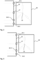
- Fig. 2 shows a possible connection by the switching device 10 according to an embodiment.
- the switching device 10 (in Fig. 2 not fully shown) each of the three connections 16-1, 16-2, 16-3 is connected to a corresponding current phase L1, L2, L3 of a 3-phase alternating current, while the star point 22 is connected to a neutral conductor N, or is connected directly to the output 17 of the switching device 10.
- the heating elements 21-i each have a heating resistor R1, R2, R2.
- no switch KN is required on the neutral conductor N and can therefore also be omitted on the switching device 10, i.e. the neutral conductor N can remain switchless. This is advantageous in areas where switching the neutral conductor N is prohibited.
- This connection enables four different heating levels, each corresponding to a different total heating output P.
- the individual setting options for the switches are listed in the first three columns (0 corresponds to "switch open", 1 corresponds to "switch closed”).
- the correspondingly set (or selected) total heating outputs P are given in the fourth column as a fraction of the maximum total heating output P max .
- the four different heating levels that can be implemented thus correspond, for example, to the total heating outputs 0, 1/3 P max , 2/3 P max and P max .
- Table 1 Available heating levels of variant S from Fig. 2 wiring according to Fig.
- the two middle heating levels corresponding to the total heating powers 1/3 P max and 2/3 P max , can be achieved in combination by three different switching combinations of the switches Ki.
- the control device 11 can be set up to periodically and/or with each new setting of one of these heating levels, successively select a different switching combination of the switches Ki in order to evenly load or wear the corresponding heating elements 21-i and the switches 16-i.
- This also applies to each of the embodiments discussed below. provided they have at least one heating level, which can be implemented using more than one switching combination. This means that switching between the switching combinations can take place periodically and/or cyclically.
- R1, R2, and R3 are all different, as in Fig. 2
- This connection enables seven different heating levels, each with a different total heating output P.
- Table 2 Available heating levels of variant A from Fig. 2 wiring according to Fig.
- R1 has the greatest ohmic resistance in the asymmetrical variants.
- the resistor designated R1 can also be connected to terminal 16-2 or 16-3, and so on in any permutation.
- Fig. 3 shows a connection through the switching device 10 according to a further embodiment.
- the The heating device 20 used is a 3-phase heating element, which, however, in contrast to the variants of Fig. 2 - is to be operated with a 1-phase power network. Accordingly, all three connections 16-i can be connected to the L1 current phase by the switching device 10.
- Fig. 4 shows a connection through the switching device 10 according to a further embodiment.
- the five heating levels correspond to the total heating outputs P of 0 (5 switching combinations), 1/3 P max (3 switching combinations), 1/2 P max (3 switching combinations), 2/3 P max (4 switching combinations), and P max (2 switching combinations).
- An asymmetrical variant would result in more heating levels.
- Even with the connection according to Fig. 4 The operation of a 1-phase heating element is possible by replacing L2 and L3 in Fig. 4 L1 is also set (not shown).
- Fig. 5 shows a connection through the switching device 10 according to a further embodiment.
- This embodiment differs from that according to Fig. 2 or 4 in that the switching device 10 here has the switch KN on the neutral conductor N, and that the output 16-2 can be switched via the switch K2 (toggle switch) between a connection with L2 or a connection with the neutral conductor N.
- the seven heating levels each correspond to the total heating output P of 0, 1/6 P max , 1/3 P max , 1/2 P max , 5/9 P max , 2/3 P max , and P max .
- the switching device 10 can have a switch (here: K2) which can be switched between one of the current phases L1, L2, L3, ie a current conductor on the one hand and the neutral conductor N on the other.
- K2 a switch
- the corresponding heating element 21-2 with its heating resistor R2 is alternatively coupled to the corresponding current phase L1, L2, L3 or the neutral conductor N.
- Table 5 Available heating levels of variant A from Fig. 5 wiring according to Fig.
- Fig. 6 shows a connection through the switching device 10 according to a further embodiment, which is a variant of the interconnection of Fig. 5 represents.
- the heating device 20 to be operated is again a 3-phase heating rod, which is to be operated with a 1-phase power supply. Accordingly, all three connections 16-i are connected to the L1 current phase by the switching device 10. This enables six heating stages to be implemented, which are listed in Table 6 below.
- Table 6 Available heating levels of variant S from Fig. 6 wiring according to Fig.
- the six heating levels each correspond to the total heating output P of 0, 1/6 P max , 1/3 P max , 2/3 P max , 2/9 P max , and P max .
- the diodes make it possible to realize additional heating stages by blocking half-waves.
- Fig. 7 shows a connection through the switching device 10 according to a further embodiment.
- a 1-phase heating device 20 is operated, which comprises a single heating element 21-i with a heating resistor R (or a sum of heating resistors, which can be represented with R as an equivalent resistor).
- the switching device 10 can be designed for such 1-phase heating devices 20 with only two connections 16-1, 17 for the L1 current conductor and the neutral conductor, or can be programmed to supply only these connections with power.
- the switching device 10 has a switch K1 that can be controlled by the control device 11 and a diode 14 connected in parallel to this switch K1.
- three heating stages can be realized, as listed in Table 7 below: 0, 1/2 P max , and P max .
- Table 7: Available heating levels of the variant from Fig. 7 wiring according to Fig. 7 : 3 heating levels K1 KN P R 26.45 ⁇ 0 0 0 0 0 1 1/2 P max 1000 W 1 0 0 0 1 1 P max 2000 W
- Fig. 8 shows a connection through the switching device 10 according to a further embodiment, which is a variant of the embodiment according to Fig. 7
- the switching device 10 has a series circuit connected in parallel with the switch K1, consisting of a further switch K1a, which can be controlled by the control device 11, and the diode 14.
- the switch K1a forms the diode 14 is connected in series.
- three heating stages can also be realized, as listed in Table 8 below: 0, 1/2 P max , and P max .
- the diode 14 (either alone in parallel with a switch K1, K2, K3 as in Fig. 7 , or in a series connection with another switch K1a, whereby this series connection is connected in parallel to a switch K1, K2, K3, as in Fig. 8 ) can also be advantageously combined with other variants, in particular with 3-phase heating devices 20.
- Fig. 9 shows a variant of the connection from Fig. 2 , which differs from this by a diode 14 connected in parallel with the switch K1 and the missing connection of the star point 22 to the neutral conductor N. Accordingly, the switching device 10 can also be designed without the connection 17 and thus, for example, have only exactly one connection 16-1, 16-2, 16-3 per current phase L1, L2, L3.
- the five heating levels that can be achieved in this way are: 0, 1/4 P max , 1/2 P max , 3/4 P max , and P max .
- Fig. 10 shows a 1-phase operated (or: 1-phase coupled) variant of the connection from Fig. 9
- the neutral conductor N can be connected to the switch K2 and the terminal 16-2 (shown) or to the switch K3 and the terminal 16-3 (not shown).
- the five heating levels that can be achieved in this way are: 0, 3/8 P max , 3/4 P max , 22/25 P max , and P max .
- Fig. 11 shows a variant of the connection from Fig. 9 , wherein the circuit or switching device 10 consists of Fig. 11 In contrast to the circuit or switching device 10 from Fig. 9 has a neutral conductor N connected to the terminal 17 of the switching device 10, which can be switched by a switch KN ("neutral conductor switch") of the switching device 10.
- the nine heating levels that can be achieved in this way are: 0, 1/6 P max , 1/4 P max , 1/3 P max , 1/2 P max , 2/3 P max , 3/4 P max , 5/6 P max and P max .
- Fig. 12 shows a 1-phase operated variant of the connection from Fig. 11 .
- the seven heating levels that can be achieved in this way are: 0, 1/6 P max , 1/3 P max , 1/2 P max , 2/3 P max , 5/6 P max , and P max .
- Fig. 13 shows a variant of the connection from Fig. 11 , which differs from this in that the diode 14 can be switched instead of the switch KN in the neutral conductor N; the symmetrical variant S is also shown.
- a further switch K1a is connected in series with the diode 14, by means of which the diode 14 (and preferably only the diode 14) can be switched in parallel to the switch K1 when the switch K1a is closed.
- the switch K1a is open, the diode plays no role in the connection.
- the seven heating levels that can be achieved in this way are: 0, 1/6 P max , 1/3 P max , 1/2 P max , 2/3 P max , 5/6 P max , and P max .
- the seven heating levels that can be achieved in this way are: 0, 1/6 P max , 1/3 P max , 1/2 P max , 2/3 P max , 5/6 P max , and P max .
- Fig. 14 shows a variant of the connection from Fig. 13 , with the two differences that it is a 1-phase connection and an asymmetrical variant A.
- the eleven heating levels that can be achieved in this way are: 0, 1/12 P max , 1/6 P max , 1/3 P max , 5/12 P max , 1/2 P max , 7/12 P max , 2/3 P max , 5/6 P max , 11/12 P max , and P max .
- Fig. 15 shows a variant of the connection from Fig. 13 , with the difference that a series circuit consisting of diode 14 and additional switch K1a, K2a, K3a is arranged on all current phases L1, L2, L3 in parallel to the respective switch K1, K2, K3 (and not only to the switch K1 as in Fig. 13 ).
- each heating level can be set in the variant from Fig. 15 with more different switching combinations.
- the heating device 20 can be set to a phase-accurate consumption.
- an unbalanced load occurs at the network connection point 31 and/or in the (in-house) power network 30, i.e. if one or more current phases L1, L2, L3 have a significantly different load than one or more of the other current phases L1, L2, L3, then the switching device 10 (e.g. by an energy management system 40) can be controlled (or control itself) in such a way that the unbalanced load is counteracted by selecting a suitable heating level and/or a suitable switching combination of the switches K1, K1a, K2, K2a, K3, K3a.
- the unbalanced load can be detected by the energy management system 40, which then either controls the switching device 10 directly accordingly, or transmits the necessary information to the switching device 10 so that the switching device 10 itself can carry out the necessary control.
- the variant from Fig. 15 is also useful in the event of an emergency power supply, for example when the public power grid 35 fails or is switched off.
- the inverter often sets up an emergency power supply in the local power grid 30 with a frequency of, for example, 53 Hz and detects this via a frequency measurement by the control unit 11, while in normal operation, for example, the 50 Hz of the public power grid 35 is present.
- Fig. 15 allows a user to manually activate a single (or several) of the power phases L1, L2, L3 of the heating device 20 via a user interface 12 (of the switching device 10, the energy management system 40 or the like), for example at the lowest heating level with a heating output greater than zero, in order not to overload the emergency power supply. If an overload or a breakdown of the emergency power supply does occur, the user can again select a different power phase L1, L2, L3 for a second or third attempt.
- this connection 16-i is connected to a heating element 21-i which has the lowest heating power or the highest heating resistance (in the examples usually R1). In this way, it is ensured that by using the diode 14 (and corresponding switching) a further heating stage is or can be provided.
- Fig. 16 shows a schematic flow chart for explaining a method according to an embodiment of the present invention, namely a method for operating a heating device 20 or for heating a medium, in particular a fluid F, by means of a heating device 20 with a plurality of heating elements 21-i, which are connected to one another in a star shape at a common star point 22 can be connected independently to an energy source.
- the method is carried out by means of the switching device 10 and/or the house system 100 according to an embodiment (in particular according to one of the Figures 1-6 and 9-15 ) of the present invention, but also independently thereof. Accordingly, the method can be adapted in accordance with all embodiments, variants, options and further developments described with reference to the switching device according to the invention or the house system according to the invention and vice versa.
- An energy management system 40 which carries out this method can, for example, also be integrated into a switching device 10 according to the invention.
- a desired total heating power P of the heating device 20 is detected, for example by a user interface 12, by an energy management system 40 or the like. Detecting the total heating power setpoint can include determining the total heating power setpoint, in particular calculating it.
- a heating level is determined (for example by the energy management system 40 or the control device 11 of the switching device 10) which corresponds as closely as possible to the detected total heating power setpoint, ie, is as close as possible. This makes it possible to advantageously keep a difference between the total heating power generated by the heating device 20 and the total heating power setpoint to a minimum. Alternatively, it can also be provided that (according to one option) the lower heating level closest to the total heating power setpoint is selected, or (according to another option) the next higher heating level to the total heating power setpoint is selected.
- heating elements 21-i of the heating device 20 are switched independently of one another via at least one associated switch Ki; K1a for (step-by-step) setting of the specific heating level. Examples of such and other switching actions as method steps can be found in the description of the Figures 1-6 and 9-15 and arise in particular from the tables listed therein.
- Fig. 17 shows a schematic flow chart to explain a method according to an embodiment of the present invention, namely a method for operating a heating device 20 or for heating a medium F by means of at least one heating element 21-i of a heating device 20.
- the method can be carried out by means of the switching device 10 and/or the domestic system 100 according to an embodiment of the present invention, but also independently thereof. Accordingly, the method can be adapted according to all embodiments, variants, options and further developments described with reference to the switching device according to the invention or the domestic system according to the invention and vice versa.
- a desired total heating power P of the heating device 20, i.e., a total heating power setpoint, is detected, for example from a user interface 12, from an energy management system 40, from a thermostat, or the like.
- a heating level is determined which corresponds as closely as possible (or exactly) to the recorded total heating output setpoint, i.e. in particular, which comes as close as possible to it.
- a step S600 for the (stepwise) setting of the specific heating level, at least one first switch K1 connected in series with at least one heating element 21-i is switched, which is connected in parallel with a diode 14, wherein the switch is arranged between a current phase L1 and the at least one heating element 21-i.
- a further switch K1a connected in series with the diode 14 and connected in parallel with the first switch K1 together with the diode 14 is also switched for the (step-by-step) setting of the specific heating level.
- This parallel connection is thus also arranged between a current phase L1 and the at least one heating element 21-i.
- Fig. 18 shows a schematic block diagram of a computer program product 200 according to an embodiment of the present invention.
- the computer program product 200 comprises executable program code 250 which, when executed, is configured to carry out the method according to an embodiment of the present invention, for example according to Fig. 16 or Fig. 17 .
- Fig. 19 shows a schematic block diagram of a non-transitory computer-readable data storage medium 300 according to an embodiment of the present invention.
- the data storage medium 300 comprises executable program code 350 which, when executed, is configured to carry out the method according to an embodiment of the present invention, for example according to Fig. 16 or Fig. 17 .
- the non-volatile computer-readable data storage medium 300 can be designed as a semiconductor memory, e.g. an SSD memory chip, or can have such a memory.
- the data storage medium 300 can also be a CD, DVD, Blu-Ray or comprise or include a magnetic storage device.
- the switching device 10 can advantageously be integrated into a house system 100 according to the invention and can be operated there. Accordingly, the methods according to Fig. 16 or Fig. 17 in all its variants and embodiments, in order to control the house system 100, and/or specifically the switching device 10.
- the home system 100 can have an energy management system 40, which can in particular control flows of electrical energy via the power grid 30, in particular between power sources and/or power consumers, such as the grid connection point 31, at least one consumer 32, a battery 60 of the home system 100, a renewable energy source 70 (for example a PV system) of the home system 100, an inverter 80 of the home system 100 and/or the like.
- an energy management system 40 can in particular control flows of electrical energy via the power grid 30, in particular between power sources and/or power consumers, such as the grid connection point 31, at least one consumer 32, a battery 60 of the home system 100, a renewable energy source 70 (for example a PV system) of the home system 100, an inverter 80 of the home system 100 and/or the like.
- Fig. 19 shows a schematic flow diagram illustrating a possible method for selecting heating levels, where the selected heating levels are represented by the various Embodiments of the present invention can be implemented. Accordingly, the switching device 10 and/or the house system 100 can be configured to carry out such a method, or the methods according to Fig. 16 or Fig. 17 be designed or modified to include such a process.
- start step S1 begins with a start step S1; however, it is understood that the described method is usually carried out cyclically, i.e. it always starts from the beginning, as shown by the arrows.
- a target temperature for the medium here (only as an example) a fluid F in a fluid tank 50, is first recorded.
- the target temperature can be specified directly by a user, for example via a user interface 12 in a smart home control application.
- the target temperature can also be specified by an algorithm which can take into account, for example, the time of day, the season and/or a user input.
- the recording S1 can also consist of maintaining an already specified target temperature.
- a current actual temperature of the fluid F in the fluid tank 50 is recorded, in particular measured.
- the actual temperature can be determined by means of a temperature sensor of the building system 100, which can be integrated into the fluid tank 50, for example.
- a step S3 it is checked whether an actual temperature of the fluid F in the fluid tank 50 is lower than a target temperature.
- tolerance range can be provided within which the process continues as if there were no difference. In this way, constant switching back and forth or other unstable control behavior can be prevented.
- the tolerance ranges can be arranged symmetrically or asymmetrically around the comparison or threshold value. The latter can be used, for example, to achieve a hysteresis effect, such that a larger deviation from the threshold value is required to revise a decision than was necessary to trigger the decision in the first place.
- corresponding tolerance ranges will not be mentioned explicitly every time in order to keep the explanations slim.
- step S4 checks whether there is excess power in the house system 100, initially from renewable energy sources 70, e.g. from a PV system. Preferably, only renewable energy sources 70 of the house system 100 are taken into account here. For the test, a current power value of at least one renewable energy source 70 can be obtained in step S4. Optionally, other power values, for example power consumed by consumers 32, etc., can also be received. From the received power values, it can be calculated in a known manner whether there is excess power from renewable energy sources 70 of the house system 100.
- a check is carried out in a step S5 to determine whether the charge level of the battery 60 is above a charge level threshold.
- This charge level threshold can, for example, indicate a charge level above which charge levels are generally undesirable, whether it is to charge the battery 60, or because such a high charge level is considered unnecessary or the like.
- the energy management system 40 controls the home system 100 in such a way that, in a step S6, an output power available on the battery 60 and released (e.g. by the customer) is added to the excess power.
- step S7 the next step in step S7 is to check whether the excess power now determined is sufficient to switch the heating device 20 to a higher heating level. Accordingly, bidirectional communication can be established between the switching device 10 and the energy management system 40, so that on the one hand the energy management system 40 knows the currently set heating level and/or the total heating output setpoint, and on the other hand it can specify a heating level to be set and/or the total heating output setpoint to the switching device 10.
- step S1 If a higher heating level is not possible (minus sign, "-" in the drawing), for example because the excess power is not sufficient, or because there is no higher heating level, the process continues at step S1. If a higher heating level is possible (plus sign, "+” in the drawing), a higher heating level is set in a step S8.
- the switching device 10 is instructed, for example by the energy management system 40 (or it decides itself) to set a higher heating level, and then by the The corresponding heating level is set by switching the switches Ki, KN, Kia in the switching device 10. The method is then continued again at step S1.
- step S4 If it is determined in step S4 that no excess power from renewable energy sources 70 is available (minus sign, "-", in the drawing), a check is carried out in step S9 as to whether electricity from the supply grid is currently being consumed, i.e. whether it is flowing into the building system 100 at the grid connection point 31. If this is not the case (minus sign, "-", in the drawing), the current heating level is maintained and the process continues at step S1.
- step S12 checks whether the actual temperature is less than a user-adjustable or predefined upper temperature threshold, which is greater than the target temperature.
- step S13 a check is made in step S13 to see whether excess power is available, initially from renewable energy sources. If this is not the case (minus sign, "-”, in the drawing), the process continues with step S9, as already explained. If excess power is available from renewable energy sources (plus sign, "+”, in the drawing under step S13), the process continues with step S7, i.e. by checking whether a higher heating level is possible.
- the procedure according to Fig. 20 thus makes it possible to use the heating of the medium F (e.g. in the fluid tank 50) to store thermal energy. However, this should not be done with electricity from the public power grid 35, but only with electrical power from renewable energy sources 70 of the house system 100, and only if the actual temperature does not exceed the upper temperature threshold.
- a charge state of the battery 60 of the house system 100 above the threshold can be used (step S5). It is understood that the person skilled in the art can adapt the method according to Fig. 20f in a variety of ways in order to carry out individual steps. add or omit in order to achieve a desired regulation or control.
- step S8 of increasing the heating level can alternatively be replaced or supplemented by a step of switching on at least one consumer 32, e.g. a heat pump.
- step S11 of reducing the heating level can alternatively be replaced or supplemented by a step of switching off at least one consumer 32, e.g. a heat pump. Switching on or switching off can also be replaced by increasing or reducing energy consumption.
Landscapes
- Engineering & Computer Science (AREA)
- Physics & Mathematics (AREA)
- Thermal Sciences (AREA)
- Chemical & Material Sciences (AREA)
- Combustion & Propulsion (AREA)
- Mechanical Engineering (AREA)
- General Engineering & Computer Science (AREA)
- Computer Hardware Design (AREA)
- Control Of Resistance Heating (AREA)
- Steam Or Hot-Water Central Heating Systems (AREA)
- Central Heating Systems (AREA)
Priority Applications (4)
| Application Number | Priority Date | Filing Date | Title |
|---|---|---|---|
| EP23189830.5A EP4502488A1 (fr) | 2023-08-04 | 2023-08-04 | Dispositif de commutation, installation domotique et procédé de fonctionnement d'un dispositif de chauffage |
| CN202480056074.9A CN121925531A (zh) | 2023-08-04 | 2024-08-02 | 开关装置、家庭系统以及用于操作加热设备的方法 |
| AU2024320996A AU2024320996A1 (en) | 2023-08-04 | 2024-08-02 | Switching device, household system and method for operating a heating apparatus |
| PCT/EP2024/072078 WO2025032017A1 (fr) | 2023-08-04 | 2024-08-02 | Dispositif de commutation, système domestique et procédé de fonctionnement d'un appareil de chauffage |
Applications Claiming Priority (1)
| Application Number | Priority Date | Filing Date | Title |
|---|---|---|---|
| EP23189830.5A EP4502488A1 (fr) | 2023-08-04 | 2023-08-04 | Dispositif de commutation, installation domotique et procédé de fonctionnement d'un dispositif de chauffage |
Publications (1)
| Publication Number | Publication Date |
|---|---|
| EP4502488A1 true EP4502488A1 (fr) | 2025-02-05 |
Family
ID=87557600
Family Applications (1)
| Application Number | Title | Priority Date | Filing Date |
|---|---|---|---|
| EP23189830.5A Withdrawn EP4502488A1 (fr) | 2023-08-04 | 2023-08-04 | Dispositif de commutation, installation domotique et procédé de fonctionnement d'un dispositif de chauffage |
Country Status (4)
| Country | Link |
|---|---|
| EP (1) | EP4502488A1 (fr) |
| CN (1) | CN121925531A (fr) |
| AU (1) | AU2024320996A1 (fr) |
| WO (1) | WO2025032017A1 (fr) |
Citations (7)
| Publication number | Priority date | Publication date | Assignee | Title |
|---|---|---|---|---|
| DE1261256B (de) * | 1958-03-27 | 1968-02-15 | Stefan Kummer | Heizflansch fuer elektrisch beheizte Heisswasserbereitungsgeraete |
| DE2928391A1 (de) * | 1979-07-13 | 1981-01-15 | Vaillant Joh Gmbh & Co | Heizflansch fuer ein elektrisch beheiztes heisswassergeraet |
| DE3021557A1 (de) * | 1980-06-07 | 1982-01-14 | Cloer Caspar Gmbh & Co Kg | Elektrisches backgeraet fuer waffeln o.ae. backerzeugnisse |
| DE3631226A1 (de) * | 1986-09-13 | 1988-03-24 | Stiebel Eltron Gmbh & Co Kg | Netzanschlussschaltung eines elektrischen warmwasserspeichers |
| DE19500522B4 (de) * | 1995-01-11 | 2004-03-25 | Eht Haustechnik Gmbh | Warmwasserbereiter mit drei elektrischen Heizelementen |
| US20060263073A1 (en) * | 2005-05-23 | 2006-11-23 | Jcs/Thg,Llp. | Multi-power multi-stage electric heater |
| EP2178337A1 (fr) * | 2008-10-17 | 2010-04-21 | DBK David + Baader GmbH | Appareil ménager doté d'un système de chauffage et procédé de commande de l'énergie de chauffage dans un appareil ménager |
-
2023
- 2023-08-04 EP EP23189830.5A patent/EP4502488A1/fr not_active Withdrawn
-
2024
- 2024-08-02 AU AU2024320996A patent/AU2024320996A1/en active Pending
- 2024-08-02 CN CN202480056074.9A patent/CN121925531A/zh active Pending
- 2024-08-02 WO PCT/EP2024/072078 patent/WO2025032017A1/fr active Pending
Patent Citations (7)
| Publication number | Priority date | Publication date | Assignee | Title |
|---|---|---|---|---|
| DE1261256B (de) * | 1958-03-27 | 1968-02-15 | Stefan Kummer | Heizflansch fuer elektrisch beheizte Heisswasserbereitungsgeraete |
| DE2928391A1 (de) * | 1979-07-13 | 1981-01-15 | Vaillant Joh Gmbh & Co | Heizflansch fuer ein elektrisch beheiztes heisswassergeraet |
| DE3021557A1 (de) * | 1980-06-07 | 1982-01-14 | Cloer Caspar Gmbh & Co Kg | Elektrisches backgeraet fuer waffeln o.ae. backerzeugnisse |
| DE3631226A1 (de) * | 1986-09-13 | 1988-03-24 | Stiebel Eltron Gmbh & Co Kg | Netzanschlussschaltung eines elektrischen warmwasserspeichers |
| DE19500522B4 (de) * | 1995-01-11 | 2004-03-25 | Eht Haustechnik Gmbh | Warmwasserbereiter mit drei elektrischen Heizelementen |
| US20060263073A1 (en) * | 2005-05-23 | 2006-11-23 | Jcs/Thg,Llp. | Multi-power multi-stage electric heater |
| EP2178337A1 (fr) * | 2008-10-17 | 2010-04-21 | DBK David + Baader GmbH | Appareil ménager doté d'un système de chauffage et procédé de commande de l'énergie de chauffage dans un appareil ménager |
Also Published As
| Publication number | Publication date |
|---|---|
| AU2024320996A1 (en) | 2026-03-12 |
| CN121925531A (zh) | 2026-04-24 |
| WO2025032017A1 (fr) | 2025-02-13 |
Similar Documents
| Publication | Publication Date | Title |
|---|---|---|
| EP2108101B1 (fr) | Four pour prothèses dentaires ou prothèses dentaires partielles | |
| DE112014001538B4 (de) | Verfahren zum Bestimmen von Strombegrenzungen für Kopplervorrichtungenund ein elektrischer Schaltkreis zum Durchführen des Verfahren | |
| DE19905074C1 (de) | Elektrische Heizvorrichtung, insbesondere PTC-Heizvorrichtung für ein Fahrzeug | |
| DE102015101738A1 (de) | Verfahren zum Betrieb einer Energieerzeugungsanlage und Energieerzeugungsanlage | |
| DE102018211633A1 (de) | Verfahren und Vorrichtung zum Aufladen elektrischer Energiespeicher | |
| EP2959492B1 (fr) | Procédé pour faire fonctionner un changeur de prises en charge avec des éléments de commutation à semi-conducteurs | |
| EP1638196A2 (fr) | Dispositif pour alimenter des charges variables | |
| EP2913734A2 (fr) | Dispositif de fonctionnement d'une installation ayant au moins un dispositif de réglage et/ou de commande de chauffage, dispositif de réglage et/ou de commande de chauffage et installation | |
| EP4502488A1 (fr) | Dispositif de commutation, installation domotique et procédé de fonctionnement d'un dispositif de chauffage | |
| DE2657784A1 (de) | Einrichtung zum abschalten einer phase einer mehrphasenversorgung | |
| EP0095479B1 (fr) | Chauffe-eau electrique | |
| DE102011122342A1 (de) | Anordnung mit zwei Fahrzeugbauteilen, insbesondere einer Lenksäule und einem Lenkrad, und Kraftfahrzeug mit einer Anordnung | |
| EP3363089B1 (fr) | Système de compensation de puissance réactive ainsi que procédé de fonctionnement d'un système de compensation de puissance réactive | |
| DE102007050341A1 (de) | Induktionsmodul, Anordnung mehrerer Induktionsmodule und Verfahren zur Einrichtung eines solchen Induktionsmoduls | |
| DE102005042560A1 (de) | PTC-Heizregister | |
| EP1067650B1 (fr) | Arrangement de commande de la distribution d'énergie électrique et procédé de fonctionnement | |
| WO2005124161A1 (fr) | Module bus permettant de commander des valves fluidiques | |
| AT503582B1 (de) | Verfahren zum betreiben mehrerer durchlauferhitzer | |
| DE59508258C5 (de) | Elektrisches Heizgerät und Verfahren zu dessen Betreiben | |
| DE19500522B4 (de) | Warmwasserbereiter mit drei elektrischen Heizelementen | |
| DE2228709B2 (de) | Verfahren und einrichtung zum betrieb einer aus mehreren elektro-heizgeraeten bestehenden heizungsanlage | |
| DE102012111046A1 (de) | Verfahren zum Begrenzen einer maximalen Leistungsaufnahme einer komplexen Produktionsmaschine, insbesondere einer Spritzgießmaschine | |
| AT402990B (de) | Vorrichtung zum steuern der auslauftemperatur eines elektrischen durchlauferhitzers | |
| DE102004005272A1 (de) | Verfahren zum Schalten von Heizeinrichtungen in einem Elektro-Kochgerät und Vorrichtung dafür | |
| EP2989646B1 (fr) | Transformateur de réseau local réglable |
Legal Events
| Date | Code | Title | Description |
|---|---|---|---|
| PUAI | Public reference made under article 153(3) epc to a published international application that has entered the european phase |
Free format text: ORIGINAL CODE: 0009012 |
|
| STAA | Information on the status of an ep patent application or granted ep patent |
Free format text: STATUS: THE APPLICATION HAS BEEN PUBLISHED |
|
| AK | Designated contracting states |
Kind code of ref document: A1 Designated state(s): AL AT BE BG CH CY CZ DE DK EE ES FI FR GB GR HR HU IE IS IT LI LT LU LV MC ME MK MT NL NO PL PT RO RS SE SI SK SM TR |
|
| STAA | Information on the status of an ep patent application or granted ep patent |
Free format text: STATUS: THE APPLICATION IS DEEMED TO BE WITHDRAWN |
|
| 18D | Application deemed to be withdrawn |
Effective date: 20250806 |