EP2178409B1 - Einsatz zur ausdehnung eines bekleidungsartikels - Google Patents
Einsatz zur ausdehnung eines bekleidungsartikels Download PDFInfo
- Publication number
- EP2178409B1 EP2178409B1 EP08796235.3A EP08796235A EP2178409B1 EP 2178409 B1 EP2178409 B1 EP 2178409B1 EP 08796235 A EP08796235 A EP 08796235A EP 2178409 B1 EP2178409 B1 EP 2178409B1
- Authority
- EP
- European Patent Office
- Prior art keywords
- zipper
- insert
- article
- clothing
- edge
- Prior art date
- Legal status (The legal status is an assumption and is not a legal conclusion. Google has not performed a legal analysis and makes no representation as to the accuracy of the status listed.)
- Not-in-force
Links
Images


Classifications
-
- A—HUMAN NECESSITIES
- A43—FOOTWEAR
- A43B—CHARACTERISTIC FEATURES OF FOOTWEAR; PARTS OF FOOTWEAR
- A43B3/00—Footwear characterised by the shape or the use
- A43B3/26—Footwear characterised by the shape or the use adjustable as to length or size
-
- A—HUMAN NECESSITIES
- A41—WEARING APPAREL
- A41D—OUTERWEAR; PROTECTIVE GARMENTS; ACCESSORIES
- A41D15/00—Convertible garments
-
- A—HUMAN NECESSITIES
- A43—FOOTWEAR
- A43B—CHARACTERISTIC FEATURES OF FOOTWEAR; PARTS OF FOOTWEAR
- A43B23/00—Uppers; Boot legs; Stiffeners; Other single parts of footwear
- A43B23/02—Uppers; Boot legs
- A43B23/04—Uppers made of one piece; Uppers with inserted gussets
- A43B23/045—Uppers with inserted gussets
- A43B23/047—Uppers with inserted gussets the gusset being elastic
-
- A—HUMAN NECESSITIES
- A43—FOOTWEAR
- A43B—CHARACTERISTIC FEATURES OF FOOTWEAR; PARTS OF FOOTWEAR
- A43B3/00—Footwear characterised by the shape or the use
- A43B3/02—Boots covering the lower leg
- A43B3/04—Boots covering the lower leg with rubber or elastic insertions or gussets
-
- A—HUMAN NECESSITIES
- A43—FOOTWEAR
- A43B—CHARACTERISTIC FEATURES OF FOOTWEAR; PARTS OF FOOTWEAR
- A43B3/00—Footwear characterised by the shape or the use
- A43B3/24—Collapsible or convertible
- A43B3/242—Collapsible or convertible characterised by the upper
-
- A—HUMAN NECESSITIES
- A41—WEARING APPAREL
- A41D—OUTERWEAR; PROTECTIVE GARMENTS; ACCESSORIES
- A41D2300/00—Details of garments
- A41D2300/20—Inserts
-
- A—HUMAN NECESSITIES
- A41—WEARING APPAREL
- A41D—OUTERWEAR; PROTECTIVE GARMENTS; ACCESSORIES
- A41D2300/00—Details of garments
- A41D2300/20—Inserts
- A41D2300/22—Elastic inserts
-
- Y—GENERAL TAGGING OF NEW TECHNOLOGICAL DEVELOPMENTS; GENERAL TAGGING OF CROSS-SECTIONAL TECHNOLOGIES SPANNING OVER SEVERAL SECTIONS OF THE IPC; TECHNICAL SUBJECTS COVERED BY FORMER USPC CROSS-REFERENCE ART COLLECTIONS [XRACs] AND DIGESTS
- Y10—TECHNICAL SUBJECTS COVERED BY FORMER USPC
- Y10T—TECHNICAL SUBJECTS COVERED BY FORMER US CLASSIFICATION
- Y10T24/00—Buckles, buttons, clasps, etc.
- Y10T24/25—Zipper or required component thereof
- Y10T24/2561—Slider having specific configuration, construction, adaptation, or material
- Y10T24/2563—Slider having specific configuration, construction, adaptation, or material including relatively movable spaced wings [i.e., restraining walls]
Definitions
- the invention generally relates to clothing and apparel and specifically to inserts for expanding an article of clothing and articles of clothing including such inserts.
- Articles of clothing are generally manufactured in different sizes. The various sizes allow people of various body sizes and shapes to wear the particular article of clothing. Some articles of clothing include a structure for fastening portions of the article of clothing together to secure a particular fit (e.g., a snug fit). Examples of these types of clothing include pants, shirts, jackets and boots.
- articles of footwear such as boots present a unique problem for wearers whose bodies are not sized in the same way the boot is designed.
- a person may have a foot size that is compatible with standard foot sizes, but the person may also have a larger calf than the leg-covering portion of the boot is designed to fit. More specifically, the circumference of the leg-covering portion of the boot, or opening, may be smaller than the circumference of the wearer's calf.
- the wearer may not be able to close the leg-covering portion of the boot to fit about the wearer's calf.
- a person would be required to forego wearing the boot or forcing the leg-covering portion to close about the calf.
- Forcing the leg-covering portion of the boot to close about the calf could lead to potential tightness in the wearer's leg from the leg-covering portion or pinched skin in the fastener. Stress on the fastener and potential ripping of the boot material or breakage of the fastener could also result from an overly tight leg-covering portion relative to the wearer's calf.
- the invention solves the problems described herein using an insert that expands a size or circumference of the article of clothing.
- the insert is designed and manufactured to employ the fastening structure of the article of clothing to facilitate expansion, therefore minimizing any structural changes to the article of clothing and reducing or eliminating the need for specific tailoring of the article of clothing.
- the insert can be sold with the article of clothing or as a separate item for use with the article of clothing.
- the insert can be removable, allowing the wearer to use different size insert as the wearer's needs change (e.g., the wearer can obtain larger inserts if the wearer's leg increases in size or smaller inserts if the wearer's leg decreases in size (until the inserts are no longer necessary)).
- the invention relates to an insert for an article of clothing, comprising the features of claim 1.
- the flexible material of the body portion includes at least one of nylon, nylon canvas, an elastic material, a leather material, a spandex material, a cotton material, a cotton blend material, a LYCRATM material, or any combination of these materials.
- the flexible material can also include a color, design or pattern selected to match, complement, correspond to, or coordinate with an article of clothing or an accessory.
- the first and second fasteners feature zippers.
- the body portion can include a second fastener structure disposed between the first and second edge of the insert. The second fastener structure and the fastener structure of the leg-covering portion of the article of footwear can be generally aligned when the insert is secured to the article of footwear.
- the body portion can include an extensive region disposed between the first and second edges, and the extensive region can cover at least a portion of the fastener structure of the leg-covering portion of the article of footwear (e.g., the zipper slider of a boot zipper).
- the insert includes an elongated portion coupled to the first edge and connectable to the second edge. The elongated portion is positioned about the outer circumference of the leg-covering portion when the first and second fasteners are secured to the fastener structure of the article of footwear.
- the body portion can define a leg-facing surface and an exterior-facing surface, which can comprise different materials.
- the exterior facing-surface of the insert can include a pocket.
- the body portion includes an adornment portion that includes a structure facilitating removable coupling of ornamental items to the insert.
- the body portion can, in some embodiments, include a concealable portion disposed between the first and second edges.
- the concealable portion extends vertically past the outer circumference of the article of footwear and is foldable to fit between a leg-facing surface of the body portion and the leg of the wearer.
- the body portion can also include a concealing portion disposed between the first and second edges that extends vertically past the outer circumference of the article of footwear and is foldable over an exterior surface of the insert, an exterior surface of the leg-covering portion of the article of footwear, or both.
- the concealing portion can be detachably coupled to the body portion.
- the perimeter includes, in some embodiments, a top edge region generally aligned with the outer circumference of the leg-covering portion when the insert is secured to the fastener structure.
- the perimeter includes a bottom region remote from the top edge region, and the first and second edges form a decreasing taper from the top edge towards the bottom region.
- the invention in another aspect, relates to an article of footwear comprising the features of claim 9.
- the invention in another aspect, relates to a method for manufacturing an insert for an article of footwear, comprising the features of claim 10.
- the body portion includes a vertical dimension and a horizontal dimension.
- the method involves associating the vertical dimension of the insert with a height of a leg-covering portion of the article of footwear and associating the horizontal dimension of the insert with a circumference of a leg of a wearer of the article of footwear.
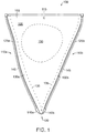
- FIG. 1 is a plan view of an insert 100 that embodies the invention.
- the insert 100 includes a body 105.
- the body 105 is formed of a flexible material or fabric.
- the flexible material is a stretchable material such as an elastic material, a spandex material, a LYCRATM material, or other stretchable materials.
- the flexible material can also be a non-stretchable material, for example, nylon, nylon canvas, leather, cotton, polyester, cotton blends, or other types of material apparent to those of skill.
- the type of material is selected based on the material of the article of clothing (not shown) with which the insert 100 will be used. For example, if the insert 100 is to be used with a leather boot, the insert 100 can be formed of a leather material.
- the body 105 includes a first edge 110a and a second edge 110b (collectively 110).
- the body 105 also includes a top edge 115.
- the top edge 115 defines a circumferential dimension C.
- the edges 110 taper away from the top edge 115 to a point 120.
- the point 120 is also a bottom edge (not shown).
- the bottom edge also includes a circumferential dimension (not shown) that can be substantially the same size as the top edge circumferential dimension C or a different size (e.g., larger or smaller than C).
- the edges 110, top edge 115, and point 120 form a perimeter of the body 105.
- the perimeter of the body 105 can be different values to facilitate different sizes for the insert 105 (e.g., in some embodiments, the edges 110 are longer than the circumferential dimension C of the top edge 115, or the length of the edges 110 can remain the same while the circumferential dimension C of the top edge 115 differs). Additionally, the circumferential dimension C can have different values depending on the amount of expansion that is preferred by the wearer.
- the length or size of the edges 110 can depend, for example, on the dimensions of the article of clothing (e.g., the edges 110 can be made a first length for a mid-calf boot and a second length for a full-calf boot). Other size and dimensional changes are within the scope of the invention.
- the insert 100 also includes a first fastener 125a disposed along the first edge 110a and a second fastener 125b disposed along the second edge 110b.
- the first fastener 125a is a zipper tape 130a
- the second fastener 125b is also a zipper tape 130b.
- the first fastener 125a and the second fastener 125b (collectively 125) are secured to the body 105 by stitching 135.
- Other ways to secure the fasteners 125 to the body 105 will be apparent, for example, gluing, bonding, or mechanical fasteners such as pins, staples, tacks, zippers or snaps.
- the first zipper tape 130a includes a first insert pin 140a and the second zipper tape 130b includes a second insert pin 140b.
- the first insert pin 140a and the second insert pin 140b (collectively 140) permit and facilitate coupling between the fasteners 125 and corresponding fasteners (not shown) on an article of clothing (not shown).
- the first zipper tape 130a and the second zipper tape 130b (collectively 130) also include zipper teeth 145.
- the zipper tape 130 can be made from a variety of materials such as, for example, nylon, metal, coil, mesh, or fabric material, or combinations of these.
- the zipper teeth 145 can similarly be made from a variety of materials such as metal, plastic, molded plastic, coil (e.g., nylon coil), or other materials suitable for a zipper. Examples of metals include brass, aluminum, antique brass, nickel, or steel.
- the fasteners 125 also each include a zipper slider (not shown) that slides along the zipper tape 130 and zipper teeth 145 from the point 120 to the top edge 115 and vice versa.
- An exemplary zipper slider is illustrated in FIG. 6A-6C .
- the zipper slider can be made from any of a variety of materials such as metal, plastic, or fabric-like materials and can have different sizes and shapes without departing from the scope of the invention.
- the zipper slider can open ( via a hinge or pivot structure), to facilitate attachment to the zipper tape 130 and zipper teeth 145 of the insert 100 as well as the zipper tape (not shown) and zipper teeth (not shown) of the corresponding article of clothing.
- zippers come in a variety of sizes, and the particular zipper teeth 145 and zipper slider are matched to the size of the corresponding fasteners (e.g., zipper) on the article of clothing.
- Exemplary zipper sizes for typical articles of clothing and footwear include YKK-sized zippers, including sizes from YKK #3 to YKK #4.5, YKK #5 and YKK #10.
- the first fastener 125a and the second fastener 125b are both two-way zippers that include two zipper sliders (not shown).
- Decorative elements such as, for example, rhinestones or sparkles can be attached to the zipper or zipper sliders.
- the circumferential dimension C serves to expand or augment a size of the article of clothing (e.g., an outer circumference of the article of clothing), while at the same time providing support to the article of clothing about the wearer's body (e.g., leg).
- any of the zipper tape 130, the zipper teeth 145, the body 105, the edges 110, the top edge 115 or the stitching 135 can be selected to be decorative (e.g., a decorative color, design, fabric type, or finish). Any of these components can be selected to match, complement, correspond, or coordinate with an article of clothing or accessory.
- the body 105 also includes an adornment region or adornment portion 150.
- the adornment region 150 can be any suitable shape or size, and the adornment region can include a material or structure that facilitates coupling ornamental features or items to the body 105.
- the adornment region 150 can be made from a VELCRO material.
- ornamental items such as, for example, charms, fabric swatches, buttons, rhinestones, sparkles, magnets, or dangly items can be attached to the adornment region 150.
- the adornment region 150 is positioned on the outward-facing surface 155 of the insert 100 (e.g., the surface not in contact with the body of the wearer).
- the inward-facing or body-facing surface (not shown) of the insert.
- the outward-facing surface 155 and the inward-facing surface are made from different materials.
- the inward-facing surface includes a material that is soft or comfortable to the touch because the inward-facing surface can come into contact with the skin of the wearer.
- the inward-facing surface can be made from a cotton material while the outward-facing surface 155 is made from a leather material.
- the inward-facing surface includes a pattern or design selected to match, complement, correspond to, or coordinate with another pattern or design (e.g., the pattern or design native to the article of clothing or an accessory, such as the lining of a purse or handbag).
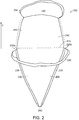
- FIG. 2 is a plan view of an insert 200 that does not comprise the first and second slider portions of claim 1.
- the insert 200 includes a first body portion 205 and a second body portion 210 that extends upwards along the y-axis from the first body portion 205.
- the first body portion 205 includes a top edge portion 215.
- the first body portion 205 and the second body portion 210 can be formed from flexible materials.
- the first body portion 205 and the second body portion 210 are formed from the same type of material or formed integrally (e.g., manufactured from the same piece of material).
- the first body portion 205 and the second body portion 210 can be formed from different types of materials.
- the second body portion 210 can be secured or fastened to the first body portion 205, for example, along the top edge 215.
- the second body portion 210 can be secured to the first body portion by bonding, gluing, or via mechanical fasteners such as buttons, snaps, clasps, VELCRO, zippers, or other types of securing mechanisms.
- the insert 200 also includes an elongated portion 220 that is connected to a first edge 225a and a second edge 225b (collectively 225) of the first body portion 205 or the second body portion 210. As illustrated, the first edge 225a and the second edge 225b are generally collinear along the extent of the first body portion 205 and the second body portion 210, but this is not necessarily required.
- the elongated portion 220 can be secured to the first edge 225a and removably securable to the second edge 225b or vice versa.
- the elongated portion 220 can be relatively permanently secured via stitching, bonding, gluing, or other permanent techniques.
- the elongated portion 220 can be removably coupled to the insert 200 via snaps, buttons, hooks, VELCRO, a zipper, clasps, or other mechanical means.
- the elongated portion can be a strap, a lace, or some other type of structure that wraps around the leg of a wearer to comfortably provide additional support or decoration for the insert 200.
- the elongated portion 220 is depicted in FIG. 2 as secured to the insert 200 at the intersection of the top edge portion 215 and the edges 225, other orientations and positions for the elongated portion 220 will be apparent and are within the scope of the invention.
- the elongated portion 220 is positioned near the inward-facing surface 230 of the insert 200.
- the insert also includes an outward-facing surface (not shown).
- the elongated portion 220 can be wrapped or tied around the body (e.g., the calf or shin) of the wearer to provide additional support and closure.
- the elongated portion 220 is decoupled from the first edge 225a or second edge 225b, wrapped around the leg of the wearer, and reattached to the edge 225 from which the elongated portion 220 was previously decoupled.
- the body portion 205 includes a zipper tape 235 along each edge 225 extending from the bottom portion 240 of the body portion 205 to the top edge portion 215.
- the zipper tape 235 extends from the bottom portion 240 to the outside edge 245 of the second body portion 210 along each edge 225.
- the first edge 225a and the second edge 225b are secured to the fastening structure (not shown) of the article of clothing, as discussed above with respect to Figure 1 (e.g., by securing the zipper tape 235 to the zipper structure of the article of clothing).
- the top edge portion 215 is generally aligned with an outside edge or perimeter (not shown) of the article of clothing (e.g., the top edge of the leg-covering portion of a boot).
- the second body portion 210 extends above or past the outside edge or perimeter of the article of clothing.
- the second body portion 210 defines an outward-facing surface 245 that can be folded over the outward-facing surface of the insert 200 upon installation, generally along the top edge portion 215. The second body portion 210 can thus be used to conceal certain features of the insert 200 as installed upon the article of clothing.
- the outward-facing surface 245 includes an adornment region (not shown) that includes a structure (not shown) that facilitates coupling ornamental or decorative features to the insert 200. Thus, the outward-facing surface 245 of the insert is visible on the outer surface of the article of clothing.
- the insert 200 includes a second elongated portion 250 coupled to the second body portion 210 at edge 240 .
- the second elongated portion 250 can be secured to the edge 240 and removably coupled to the edge 240 or vice versa, to facilitate securing the second elongated portion 250 and the second body portion 210 to the leg of a wearer (e.g., the mid-calf or ankle of the wearer) in a fashion similar to that described above for the elongated portion 220.
- the second elongated portion 250 is positioned at an intersection between edges 225 and edge 240.
- the second elongated portion 250 can also be positioned along edges 225 of the second body portion 210.
- the second elongated portion 250 is not required. Both the elongated portion 220 and the second elongated portion 250 can be made from a variety of materials, patterns or designs selected to match, complement, coordinate with or correspond to other portions of the insert 200, article of clothing, or accessories thereto.
- the second body portion 210 can also be positioned between the inward-facing surface 230 of the first body portion 205 and the leg of the wearer.
- the outward-facing surface 245 of the second body portion 210 is folded inwardly towards the inward-facing surface 230 of the first body portion 205 (e.g., between the leg of the wearer and the insert 200). After folding, the second body portion 210 is concealed within the article of clothing and not necessarily visible.
- the inward-facing surface 230 of the first body portion 210 and the outward-facing surface 245 of the second body portion 205 are in contact within the article of clothing.
- the insert 200 may not include the second elongated portion 250 in such an embodiment.
- FIG. 3 is an elevational view of a boot 300 including an insert 305.
- the boot includes a fastener structure 310.
- the fastener structure 310 is a zipper with a first zipper structure 320a (including zipper tape and zipper teeth) and a second zipper structure 320b (including zipper tape and zipper teeth) (collectively 320) and a zipper slider 325.
- the fastener structure 310 can include other types of securing or fastening mechanisms, such as, for example, buttons, snaps, hooks, clasps, VELCRO, or any combination of this, either in combination with the zipper structure 320 or as a substitute for the zipper structure 320.
- the zipper slider 325 operates to fasten the first zipper structure 320a to the second zipper structure 320b, thereby securing the leg-covering portion 330 of the boot about a leg of a wearer (not shown).
- the leg-covering portion 330 defines an outer circumference C 1 when the boot 300 is worn without the insert 305.
- the shape of the boot 300 without the insert 305 illustrated by dotted lines 300'.
- the insert 305 includes a top edge 335 that defines a circumferential portion C 2 .
- the circumferential extent C 3 of the boot 300 expands, facilitating securing the leg-covering portion 330 about the leg of the wearer.
- the shape of the boot 300 with the insert 305 in use is illustrated by lines 340. As can be seen in FIG. 3 , the insert 305 expands the size of the wearer's leg that the boot 300 can accommodate.
- the insert 305 is secured to the boot 300 by a first zipper slider 345a and a second zipper slider 345b (collectively 345).
- the zipper sliders 345 can be, for example, the zipper slider illustrated in Figure 6 that "opens" about a hinged structure to facilitate securing the zipper slider 345 to the zipper structure 320 of the boot 300.
- the insert 305 includes a first zipper structure 350a and a second zipper structure 350b. When the zipper slider 345a is in the open position, the first zipper structure 350a of the insert is positioned near the zipper structure 320a of the boot 300. The zipper slider 345a is moved to the closed position with teeth from the zipper structure 320a and zipper structure 350a therein.
- the zipper slider 345a can then be moved towards the top edge 335 of the insert 305 to fasten the zipper structure 320a to the zipper structure 350a (and to fasten the insert 305 to the leg-covering portion 330 of the boot 300).
- the zipper slider 345b couples the zipper structure 320b of the leg-covering portion 330 of the boot 300 to the zipper structure 350b of the insert 305 similarly to secure the leg-covering portion 330 about the leg of the wearer.
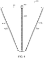
- FIG. 4 is a plan view of an insert 400 that includes a fastening structure 405 disposed relative to a flexible body 410.
- the body 410 includes a first edge 415a that includes a second fastening structure 420a and a second edge 415b that includes a second fastening structure 420b.
- the first fastening structure 420a and the second fastening structure 420b are used to attach the insert 400 to an article of clothing such as a boot (not shown).
- the fastening structure 405 positioned between the first edge 415a and the second edge 415b is illustrated as a zipper structure, but other fasteners are within the scope of the invention, e.g., snaps, hooks, clasps, laces, VELCRO, buttons, or any combination of these.
- the fastening structure 405 aligns with the fastening structure of the article of clothing, for example, the fastening structure 310 of the boot 300 of FIG. 3 .
- the fastening structure 405 can thus give the appearance of a continuous fastening structure (e.g., fastening structure 310 of the boot 300 and fastening structure 405 of the insert 400) on the article of clothing.
- the fastening structure 405 is not necessarily aligned with the fastening structure of the article of clothing.
- the body 410 can be made from any of a variety of materials and/or designs that are selected for functional or decorative purposes.
- the fastening structure 405 includes a zipper slider 425 that is used to open and close the fastening structure 405.
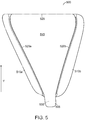
- FIG. 5 is a plan view of an insert 500 that includes both a bottom portion 505 to conceal a portion of a fastening structure of a boot and portions 510a-510b to conceal the structures that fasten the insert 500 to the boot.
- the insert 500 includes an inward-facing surface 515 that faces an interior (not shown) of a boot when the insert 500 is attached to the boot (e.g., facing and/or contacting the leg of the wearer).
- the insert 500 includes a first fastening structure 520a and a second fastening structure 520b (e.g., zippers) that secure the insert 500 to the boot, for example, as described above.
- the first fastening structure 520a is positioned near the portion 510a
- the second fastening structure 520b is positioned near the portion 500b.
- the portions 510a-510b are generally parallel to the inward-facing surface 515 and are designed to conceal the first and second fastening structures 520a-520b when the insert 500 is attached to the boot (e.g., when the first and second fastening structures 520a-520b are coupled to the corresponding fastening structures (not shown) on the leg-covering portion (not shown) of the boot.
- the fastening structures 520a-520b of the insert 500 and the fastening structure of the boot are disposed between the exterior surface (not shown) of the boot and the inward-facing portions 510a-510b.
- the portions 510a-510b include a securing structure (not shown) to secure the portions 510a-510b of the boot.
- the portions 510a-510b can include snaps, hooks, buttons, VELCRO or some other structure to couple to a corresponding structure of the boot (provided the boot includes such a structure).
- the portions 510a-510b can also be made from a relatively stiff material to ensure that the portions 510a-510b remain positioned to conceal the portions 520a-520b of the insert and corresponding fastening structure on the boot.
- the insert 500 also includes the bottom portion 505 that extends downwardly along the y-axis away from the top edge 525 of the insert 500.
- the bottom portion 505 can be used to conceal a zipper slider (not shown) on the fastening structure of the boot (e.g., the zipper slider 325 of the boot 300 in FIG. 3 ).
- the zipper slider can be concealed (e.g., tucked) between the exterior surface of the boot's fastening structure and the inward-facing surface 530 of the portion 505.
- the bottom portion 505 can include a securing structure (not shown) to couple to a corresponding securing structure of the boot (e.g., if the boot includes such a structure) to secure the bottom portion 505 in position.
- the bottom portion 505 includes a relatively stiff material that positions the bottom portion 505 relative to the zipper slider of the boot. In some embodiments, the bottom portion 505 includes a magnet for magnetic coupling to the zipper slider of the boot to keep the bottom portion 505 and/or the boot's zipper slider in position.
- the insert 500 includes either the concealing portions 510a-510b or the bottom portion 505 but not both.
- FIG. 6A is a perspective view of a zipper slider 600 for use in an insert in a closed position.
- the zipper slider 600 includes a zipper pull 605 that is coupled to a top component 610.
- the zipper pull 605 can rotate about a pivot point 615.
- the zipper pull 605 can rotate from a first position generally parallel to Line A to a second position generally parallel to Line B, or any position therebetween.
- the zipper slider 600 also includes a bottom component 620.
- the bottom component 620 is spaced from the top component 610 by a gap G in the closed position of FIG. 6A .
- the gap G allows a portion of a zipper (not shown), such as a zipper tape and zipper teeth to pass through the zipper slider 600 for fastening (e.g., or allows the zipper slider 600 to pass over the zipper for fastening).
- the bottom component 620 is coupled to the top component 610 via a pivot structure 625.
- the pivot structure 625 allows the zipper slider 600 to be moved from the closed position of FIG. 6A to the open position of FIG. 6B .
- FIG. 6B is a perspective view of a zipper slider for use in an insert in an open position.
- the top component 610 is rotated or pivoted about the pivot structure 625 away from the bottom component, thus increasing a size of the gap G between the top component 610 and the bottom component 620.
- the larger size of the gap G in the open position allows the zipper (e.g., two zipper tapes and/or zipper teeth) to be decoupled from the zipper slider 600.
- the zipper slider 600 can be removed by moving the zipper slider 600 in the direction of the uncoupled zipper (e.g., towards the unfastened portions of the zipper and away from the fastened or coupled portion of the zipper).
- the zipper slider 600 is moved to the open position of FIG. 6B by positioning the zipper pull 605 near the Line B and applying a pressure to the zipper pull 605 in the direction indicated as 630' while at the same time applying a pressure to the bottom component 620 in the direction indicated as 630" to move the top component 610 about the pivot structure 625 and increasing the size of the gap G.
- the zipper slider 600 can also be positioned relative to two uncoupled zipper structures or fasteners and moved into the closed position of FIG. 6A to facilitate coupling of the zipper structures.
- the zipper slider 600 can be used to couple a fastener (not shown) of an insert (not shown) to a corresponding fastener (not shown) of an article of clothing (not shown).
- the detailed operation of the zipper slider 600 to couple an insert to an article of clothing can be seen with reference to FIG. 3 .
- the wearer inserts a foot into the boot 300 and moves the zipper slider 325 towards the top edge 335, thereby fastening the first zipper structure 320a to the second zipper structure 320b of the boot 300 to form the coupled fastener structure 310.
- the insert 305 is positioned between the first and second zipper structures 320a-320b.
- the zipper slider 600 (depicted as 345a in FIG. 3 ), in the open position of FIG. 6B is positioned such that the first zipper structure 320a of the boot 300 and the zipper structure 350a of the insert 305 are inside the zipper slider 600.
- the zipper structure 600 is then moved to the closed position of FIG.
- FIG. 6C is an exploded perspective view of the zipper slider 600 of FIGS. 6A-6B .
- the top component 610 includes a portion 635 of the pivot structure 625 of FIGS. 6A-6B .
- the portion 635 includes a first plate 640a and a second plate 640b.
- the first plate 640a includes a pivot point 645a and the second plate 640b includes a second pivot point 645b.
- the first pivot point 645a is disposed in a facing relation to the second pivot point 645b and is spaced therefrom to facilitate coupling to the corresponding plate 650 of the bottom component 620.
- the plate 650 of the bottom component 620 includes a bore 655 therethrough configured to accept the first pivot point 645a and the second pivot point 645b and allow rotational movement of the first and second pivot points 645a-645b about the bore 655. Rotation movement of the first and second pivot points 645a-645b facilitates rotational movement of the top component 610 relative to the bottom component 620, thereby facilitating movement of the zipper structure from the open position to the closed position, and vice versa.
- first and second plates 640a-640b could be formed as a part of the bottom component 620 and the corresponding plate 650 could be formed as part of the top component 610 with departing from the scope of the invention.
- An advantage realized by the zipper slider 600 of FIG. 6C derives from the use of pivot points 645a-645b to couple the top component 610 to the bottom component 620.
- Previous designs involved a bore (not shown) through the first and second plates 640a-640b to align with the bore 655 through the corresponding plate 650, and a pin (not shown) to be positioned through the aligned bores.
- the implementation illustrated in FIG. 6C removes the need for a separate pin component, which reduces the amount of material required and amount of assembly time required for the zipper slider 600.
- the top component 610 includes an outer guide 660 for guiding a zipper structure (not shown) through the zipper slider 600.
- the bottom component includes an inner guide 665.
- the space between the outer guide 660 and the inner guide 665 when the zipper slider 600 is assembled defines a first opening (disposed on either side of the plate 650 and plates 640a-640b).
- Zipper structures are passed along lines 670a and 670b through the zipper slider 600 as the zipper slider 600 is moved in a direction generally parallel to 675. Moving the zipper slider 600 in a direction generally parallel to 675 facilitates coupling of the zipper structures as they pass through the first opening on either side of plates 640a-640b, 650 through a second, smaller opening near the back area 680 of the zipper slider 600. Moving the zipper slider 600 in a generally antiparallel to 675 facilitates de-coupling of the zipper structures as they pass from the smaller, second opening towards the larger first opening on either side of plates 640a-640b, 650.
- the top component 610, the bottom component 620, the zipper pull 605, or any other part of the zipper slider can be selected to be decorative or to match, complement, correspond, or coordinate with an article of clothing or an accessory.
- FIG. 7 is a plan view of an insert 700 for an article of clothing, such as a jacket 705.
- the jacket 705 includes a first zipper structure 710a that includes a retaining box 715 and a zipper slider 720.
- the zipper slider 720 can be the zipper slider with which the jacket 705 was manufactured.
- the jacket 705 includes a second zipper structure 710b that includes an insert pin 725.
- the insert pin 725 slides through the zipper slider 720 and into the retaining box 715.
- the zipper slider 720 is then moved away from the retaining box 715 along the first and second zipper structures 710a-710b to facilitate coupling therebetween and sealing of the jacket 705.
- the insert 700 includes a first zipper structure 730a that includes an insert pin 735.
- the insert 700 includes a second zipper structure 730b that includes a retaining box 740 and a zipper slider 745.
- the insert 700 is fastened to the jacket in the following, exemplary way.
- the insert pin 735 of the first zipper structure 730a of the insert 700 slides (or is slid) through the zipper slider 720 and retaining box 715 of the jacket 700.
- the zipper slider 720 is then moved away from the retaining box 715 along the first zipper structure 710a of the jacket 705 and the first zipper structure 730a of the insert 700 to facilitate coupling therebetween.
- the insert pin 725 of the second zipper structure 710b of the jacket 705 slides (or is slid) through the zipper slider 745 and retaining box 740 of the second zipper structure 730b of the insert 705.
- the second zipper slider 745 is moved away from the retaining box 740 along the second zipper structure 730b of the insert 705 and the second zipper structure 710b of the jacket 705 to facilitate coupling therebetween.
- the size (e.g., circumference) of the jacket can be increased without requiring tailoring or additional structural changes to the jacket.
- the insert 700 can be decorative or include a variety of materials.
- the pattern or design can be selected to match, complement, correspond to or coordinate with accessories or articles of clothing.
- the insert 700 can include an adornment portion (not shown) that includes a structure for coupling decorative items to the insert 700.
- FIG. 7 has been described in the context of a jacket 705, it will be apparent that the insert 700 can be used with other articles of clothing that include other types of fastener structures.
- any of the elements described herein can be selected based on the user's preference, including the material, size, color, pattern, design, or adornment features to add to various components. While not specifically set out for every possible combination above, components of disclosed structures (e.g., stitching attaching zipper structures to flexible bodies) can also be selected based on visual appearance or pleasing nature to the eye.
Landscapes
- Engineering & Computer Science (AREA)
- Textile Engineering (AREA)
- Footwear And Its Accessory, Manufacturing Method And Apparatuses (AREA)
- Slide Fasteners (AREA)
Claims (11)
- Ein Einsatz für einen Bekleidungsartikel, der einen körperbedeckenden Teil und einen verschließbaren Teil mit einer Reißverschlussstruktur einschließt, die den körperbedeckenden Teil um den Körper eines Trägers befestigt, der körperbedeckenden Teil definiert dabei einen Außenumfang, wenn der verschließbare Teil geschlossen ist, der Einsatz weist dabei Folgendes auf:einen Körper-Teil, der ein flexibles Material aufweist, der Körper-Teil definiert dabei einen Umfang, der einen ersten Rand und einen zweiten Rand einschließt;einen ersten Reißverschluss, der entlang des ersten Rands angebracht ist und an einem ersten Teil der Reißverschlussstruktur des körperbedeckenden Teils des Bekleidungsartikels befestigt werden kann; undeinen zweiten Reißverschluss, der entlang des zweiten Rands angebracht ist und an einem zweiten Teil der Reißverschlussstruktur des körperbedeckenden Teils des Bekleidungsartikels befestigt werden kann;wobei der Umfang des Körper-Teils eine Größe des Außenumfangs des körperbedeckenden Teils erhöhen soll, wenn der erste und der zweite Reißverschluss an der Reißverschlussstruktur befestigt werden;wobei die Reißverschlussstruktur des körperbedeckenden Teils des Bekleidungsartikels eine erste Schiene und eine zweite Schiene einschließt, der erste Reißverschluss weist dabei eine dritte Reißverschlussschiene und einen ersten Schieber-Teil auf, der die erste und dritte Reißverschlussschiene verbindet, und der zweite Reißverschluss weist eine vierte Reißverschlussschiene und einen zweiten Schieber-Teil auf, der die zweite und vierte Reißverschlussschiene verbindet; undwobei der erste und zweite Schieber-Teil jeweils eine obere Komponente einschließen, die mit einer unteren Komponente über eine Gelenk- oder Drehstruktur verbunden wird und wobei die Gelenk- oder Drehstruktur ermöglicht, dass der erste Schieber-Teil geöffnet wird und eine Verbindung zwischen der ersten und dritten Reißverschlussschiene hergestellt wird, und wobei die zweite Gelenk- oder Drehstruktur ermöglicht, dass der zweite Schieber-Teil geöffnet wird und eine Verbindung zwischen der zweiten und vierten Reißverschlussschiene hergestellt wird.
- Der Einsatz gemäß Anspruch 1, wobei der Bekleidungsartikel ein Schuhartikel und der körperbedeckende Teil ein beinbedeckender Teil ist.
- Der Einsatz gemäß Anspruch 1, wobei die dritte Reißverschlussschiene einen ersten Einsatzstift und die vierte Reißverschlussschiene einen zweiten Einsatzstift einschließt.
- Der Einsatz gemäß Anspruch 1, wobei entweder:i) das flexible Material mindestens entweder Nylon, Nylon-Kanevas, ein elastisches Material, ein Leder-Material, ein Elasthan-Material, ein Baumwoll-Material, ein Baumwoll-Mischmaterial, ein LYCRA(TM)-Material oder eine Kombination daraus aufweist,ii) das flexible Material eine Farbe oder ein Design aufweist, die so gewählt sind, dass sie zu einem Bekleidungsartikel oder einem Zubehörteil passen, diese ergänzen oder einem Bekleidungsartikel oder einem Zubehörteil entsprechen,iii) der Körper-Teil einen extensiven Bereich einschließt, der sich zwischen dem ersten und dem zweiten Rand befindet, der extensive Bereich deckt dabei mindestens einen Teil der Reißverschlussstruktur des körperbedeckenden Teils des Bekleidungsartikels ab,iv) und weist darüberhinaus einen länglichen Teil auf, der mit dem ersten Rand verbunden ist und mit dem zweiten Rand verbunden werden kann, der längliche Teil ist dabei um den Außenumfang des körperbedeckenden Teils positioniert, wenn der erste und der zweite Reißverschluss an der Reißverschlussstruktur des Bekleidungsartikels befestigt sind,v) wobei der Körper-Teil darüberhinaus einen Verzierungs-Teil aufweist, der eine Struktur einschließt, die die lösbare Verbindung der Zierelemente am Einsatz ermöglicht,vi) der Körper-Teil weist darüberhinaus einen verdeckbaren Teil auf, der zwischen dem ersten und zweiten Rand angebracht ist, der verdeckbare Teil erstreckt sich vertikal am Außenumfang des Bekleidungsartikels vorbei und ist faltbar, um zwischen eine zum Körper zeigende Fläche des Körper-Teils und den Körper des Trägers zu passen,vii) wobei der Umfang einen oberen Randbereich einschließt, der im Allgemeinen am Außenumfang des körperbedeckenden Teils ausgerichtet ist, wenn der Einsatz an der Reißverschlussstruktur befestigt ist, und einen unteren Bereich, der entfernt vom oberen Randbereich liegt, der erste Rand und der zweite Rand bilden dabei einen kleiner werdenden Konus vom oberen Rand zum unteren Bereich.
- Der Einsatz gemäß Anspruch 1, wobei der Körper-Teil darüberhinaus eine zweite Reißverschlussstruktur aufweist, die zwischen dem ersten Rand und dem zweiten Rand angebracht ist, und optional oder vorzugsweise, wobei die zweite Reißverschlussstruktur und die Reißverschlussstruktur des körperbedeckenden Teils des Bekleidungsartikels im Allgemeinen bündig ausgerichtet sind, wenn der Einsatz am Bekleidungsartikel befestigt wird.
- Der Einsatz gemäß Anspruch 1, wobei der Körper-Teil eine zum Körper gerichtete Fläche und eine nach außen gerichtete Fläche definiert.
- Der Einsatz gemäß Anspruch 6, wobei entweder:i) die zum Körper gerichtete Fläche und die nach außen gerichtete Fläche verschiedene Materialien aufweisen,ii) die nach außen gerichtete Fläche eine Tasche aufweist, oderiii) die zum Bein gerichtete Fläche ein Elasthan-Material, ein Baumwoll-Material, ein LYCRA(TM)-Material, ein elastisches Material oder eine Kombination daraus aufweist,
- Der Einsatz gemäß Anspruch 1, wobei der Körper-Teil darüberhinaus einen verdeckbaren Teil aufweist, der zwischen dem ersten und zweiten Rand angebracht ist, der verdeckbare Teil erstreckt sich vertikal am Außenumfang des Bekleidungsartikels vorbei und ist faltbar über einer Außenfläche des Einsatzes, einer Außenfläche des beinbedeckenden Teils des Bekleidungsartikels oder über beidem, und
optional oder vorzugsweise ist der bedeckende Teil abnehmbar mit dem Körper-Teil verbunden. - Ein Schuhartikel, der Folgendes aufweist:einen beinbedeckenden Teil und einen schließbaren Teil mit einer Reißverschlussstruktur, die einen ersten Teil und einen zweiten Teil einschließt, die zusammengefügt werden, um das beinbedeckende Teil um ein Bein des Trägers zu befestigen, das beinbedeckende Teil definiert dabei einen Außenumfang, wenn die Reißverschlussstruktur geschlossen ist; undeinen Einsatz gemäß Anspruch 2.
- Ein Verfahren zur Herstellung eines Einsatzes für einen Schuhartikel, das Verfahren weist dabei Folgendes auf:die Bildung eines Körper-Teils aus einem flexiblen Material, der Körper-Teil definiert dabei einen Umfang, der einen ersten Rand und einen zweiten Rand einschließt;die Auswahl eines ersten Reißverschlusses, der mit einer ersten entsprechenden Reißverschlussstruktur des Bekleidungsartikels verbunden wird;die Befestigung des ersten Reißverschlusses entlang des ersten Randes;die Auswahl eines zweiten Reißverschlusses, der mit einer zweiten entsprechenden Reißverschlussstruktur des Bekleidungsartikels verbunden wird;die Befestigung des zweiten Reißverschlusses entlang des zweiten Randes; unddie Bereitstellung eines ersten Schieber-Teils für die Verbindung des ersten Reißverschlusses mit der ersten entsprechenden Reißverschlussstruktur des Schuhartikels und einen zweiten Schieber-Teil für die Verbindung des zweiten Reißverschlusses mit der zweiten entsprechenden Reißverschlussstruktur des Schuhartikels;wobei der erste und zweite Schieber-Teil jeweils eine obere Komponente einschließen, die mit einer unteren Komponente über eine Gelenk- oder Drehstruktur verbunden wird und wobei die erste Gelenk- oder Drehstruktur ermöglicht, dass der erste Schieber-Teil geöffnet und eine Verbindung zwischen dem ersten Reißverschluss und der ersten entsprechenden Reißverschlussstruktur hergestellt wird, und wobei die zweite Gelenk- oder Drehstruktur ermöglicht, dass der zweite Schieber-Teil geöffnet und eine Verbindung zwischen dem zweiten Reißverschluss und der zweiten entsprechenden Reißverschlussstruktur hergestellt wird.
- Das Verfahren gemäß Anspruch 10, wobei der Körper-Teil eine vertikale Dimension und eine horizontale Dimension einschließt, das Verfahen weist darüberhinaus Folgendes auf:die Verbindung der vertikalen Dimension des Einsatzes mit einer Höhe eines beinbedeckenden Teils des Schuhartikels; unddie Verbindung der horizontalen Dimension des Einsatzes mit einem Umfang eines Beins des Trägers des Schuhartikels.
Applications Claiming Priority (2)
| Application Number | Priority Date | Filing Date | Title |
|---|---|---|---|
| US96115007P | 2007-07-18 | 2007-07-18 | |
| PCT/US2008/070326 WO2009012383A2 (en) | 2007-07-18 | 2008-07-17 | Insert for expanding an article of clothing |
Publications (2)
| Publication Number | Publication Date |
|---|---|
| EP2178409A2 EP2178409A2 (de) | 2010-04-28 |
| EP2178409B1 true EP2178409B1 (de) | 2016-04-06 |
Family
ID=39791700
Family Applications (1)
| Application Number | Title | Priority Date | Filing Date |
|---|---|---|---|
| EP08796235.3A Not-in-force EP2178409B1 (de) | 2007-07-18 | 2008-07-17 | Einsatz zur ausdehnung eines bekleidungsartikels |
Country Status (4)
| Country | Link |
|---|---|
| US (1) | US8136267B2 (de) |
| EP (1) | EP2178409B1 (de) |
| CA (2) | CA2898208C (de) |
| WO (1) | WO2009012383A2 (de) |
Families Citing this family (18)
| Publication number | Priority date | Publication date | Assignee | Title |
|---|---|---|---|---|
| US7913427B2 (en) * | 2007-09-27 | 2011-03-29 | Nike, Inc. | Article of footwear for riding |
| FR2954896A1 (fr) * | 2010-01-05 | 2011-07-08 | Corinne Michelle Ministrini | L'invention concerne un article chaussant de ville qui est a l'origine une paire de bottes que l'on peut transformer en chaussures ou bottines |
| AU2011276482A1 (en) * | 2010-06-29 | 2013-02-21 | Jennifer Digrazia | Wound and bandage protection system and method |
| US20120216333A1 (en) * | 2011-02-25 | 2012-08-30 | Dewese Charles D | Fashion or sports accessory using fabric and attachment mechanism to fasten around a person's neck |
| US9254015B2 (en) * | 2011-11-25 | 2016-02-09 | Samantha Nugent | Non-gaiter bootleg cover |
| US10299532B2 (en) * | 2012-11-14 | 2019-05-28 | David Cherosky | Water-proof protective shoe covering |
| US9254017B2 (en) * | 2013-01-10 | 2016-02-09 | DM3, Inc. | Expandable footwear for children |
| WO2015002640A1 (en) * | 2013-07-02 | 2015-01-08 | Hampton Tammy Rice | Zipper repairer and extender |
| CA2973004A1 (en) * | 2015-01-03 | 2016-07-07 | Extendher Llc | Extender for an outerwear |
| EP3340818A1 (de) * | 2015-08-25 | 2018-07-04 | Williams, Paul, H. | Kleidungsstück mit einem abnehmbaren und austauschbaren modestreifen |
| US11013290B2 (en) * | 2016-08-18 | 2021-05-25 | Cabela's Llc | Manufacturing process and design for a waterproof boot |
| US11330867B2 (en) * | 2017-01-17 | 2022-05-17 | William I. Craven, Sr. | Removable shoe lace replacement overlay and method of using same |
| USD1006427S1 (en) | 2017-12-29 | 2023-12-05 | William I. CRAVEN | Removable shoe lace replacement overlay |
| US11253402B2 (en) * | 2018-03-03 | 2022-02-22 | Fastform Research Ltd. | Orthosis apparatus and method of use |
| US11684124B2 (en) * | 2020-09-24 | 2023-06-27 | Charles H. Brown, III | Accessory wearable around a boot shaft |
| US20230103052A1 (en) * | 2021-09-24 | 2023-03-30 | Filip Postolek | Footwear with dual rear closure arrangement |
| EP4586843A1 (de) * | 2022-09-16 | 2025-07-23 | DuPont Safety & Construction, Inc. | Schutzkleidung mit verschlussklappe |
| US20250288048A1 (en) * | 2024-03-15 | 2025-09-18 | Honeywell Safety Products Usa, Inc. | Calf adjustable boot |
Citations (1)
| Publication number | Priority date | Publication date | Assignee | Title |
|---|---|---|---|---|
| GB2023402A (en) * | 1978-06-22 | 1980-01-03 | Drew J A | Orthopaedic shoe |
Family Cites Families (36)
| Publication number | Priority date | Publication date | Assignee | Title |
|---|---|---|---|---|
| US587483A (en) * | 1897-08-03 | Boot or shoe | ||
| US343410A (en) * | 1886-06-08 | Geoege a | ||
| US664044A (en) * | 1900-04-23 | 1900-12-18 | Rudolf Hoermann | Boot or shoe. |
| US1200388A (en) * | 1914-12-29 | 1916-10-03 | Charles E Mason | Shoe. |
| US1349572A (en) * | 1919-11-07 | 1920-08-17 | Goodyear S India Rubber Glove | Boot |
| US1642737A (en) * | 1923-02-27 | 1927-09-20 | Goodrich Co B F | Shoe |
| US1684660A (en) * | 1924-03-15 | 1928-09-18 | Mishawaka Rubber & Woolen Mfg | Shoe |
| US1777137A (en) * | 1925-05-21 | 1930-09-30 | Mishawaka Rubber & Woolen Mfg | Flexible reenforcing |
| US1632390A (en) * | 1926-12-06 | 1927-06-14 | Joseph M Dietz | Arctic |
| US1771004A (en) * | 1927-12-12 | 1930-07-22 | Mishawaka Rubber & Woolen Mfg | Form-fitting boot |
| US1765096A (en) * | 1929-05-21 | 1930-06-17 | Reingold Meyer | Waterproof overalls |
| US2108650A (en) * | 1936-02-28 | 1938-02-15 | Converse Rubber Company | Overshoe |
| US2159816A (en) * | 1936-12-04 | 1939-05-23 | James T Murphy | Boot and the like |
| US2178885A (en) | 1936-12-08 | 1939-11-07 | Buff | Double closure, jointly operated, for flexible articles |
| US2287877A (en) * | 1940-08-02 | 1942-06-30 | Goodyear Footwear Corp | Rubber shoe |
| US2437765A (en) * | 1945-03-17 | 1948-03-16 | Statham Noel | Adjustable fastening device |
| US2495176A (en) | 1946-02-01 | 1950-01-17 | Zip Clip Zipper Corp | Reversible slider for slide fasteners |
| US2666996A (en) * | 1951-07-18 | 1954-01-26 | Inv Dev Corp | Overshoe with gusset and tongue |
| US2973589A (en) * | 1959-02-09 | 1961-03-07 | Rowena N Rigsby | Adjustable baby shoe |
| US2986824A (en) * | 1960-03-31 | 1961-06-06 | Cambridge Rubber Co | Overshoe having bellows tongue and slide fastener |
| US3059352A (en) * | 1960-05-02 | 1962-10-23 | Scovill Manufacturing Co | Closures for front openings in footwear |
| US3763579A (en) | 1972-03-13 | 1973-10-09 | R Dexter | Extensible zippered closure for boots |
| US3855715A (en) | 1973-10-05 | 1974-12-24 | Raymond Lee Organization Inc | Boot zipper |
| US4512089A (en) * | 1982-09-07 | 1985-04-23 | Anthony Carrier | Winter boot |
| US4689902A (en) * | 1984-12-03 | 1987-09-01 | Anthony E. Deprima | Breakaway riding boot |
| FR2593356A1 (fr) | 1985-12-10 | 1987-07-31 | Preixens Catherine | Systeme de camouflage pour rendre invisible les liaisons additionnelles de vetements composes de pieces interchangeables et amovibles |
| JPS6373310U (de) * | 1986-10-31 | 1988-05-16 | ||
| CA2104496A1 (en) | 1993-08-20 | 1995-02-21 | Glen Ronald | Modular panel for fabricating clothing and accessories |
| DE19624553A1 (de) * | 1996-06-20 | 1998-01-02 | Schabsky Atlas Schuhfab | Stiefel |
| US6604477B1 (en) * | 2001-06-11 | 2003-08-12 | Oltea Hozan | Method of manufacture for a boot for the physically impaired |
| DE20212408U1 (de) | 2002-08-13 | 2002-11-14 | Zessler, Silke, 37081 Göttingen | Zusammensetzbare Kleidungsstücke oder Accessoires |
| DE10240785B4 (de) | 2002-08-30 | 2004-09-16 | Ewald Haimerl | Stiefel mit einem teilbaren Reißverschluß |
| US20050034329A1 (en) * | 2003-08-12 | 2005-02-17 | Eddie Chen | Shoe with adjustment pad unit |
| US7231671B2 (en) * | 2005-02-18 | 2007-06-19 | Bradley Allen | Adjustable leg width trousers |
| GB0516023D0 (en) | 2005-08-04 | 2005-09-14 | Clark C & J Int Ltd | An article of footwear |
| SE530254C2 (sv) | 2006-11-01 | 2008-04-08 | Jens Leveau | Zlide On |
-
2008
- 2008-07-17 WO PCT/US2008/070326 patent/WO2009012383A2/en not_active Ceased
- 2008-07-17 CA CA2898208A patent/CA2898208C/en active Active
- 2008-07-17 EP EP08796235.3A patent/EP2178409B1/de not_active Not-in-force
- 2008-07-17 CA CA2694763A patent/CA2694763C/en active Active
- 2008-07-17 US US12/175,169 patent/US8136267B2/en active Active
Patent Citations (1)
| Publication number | Priority date | Publication date | Assignee | Title |
|---|---|---|---|---|
| GB2023402A (en) * | 1978-06-22 | 1980-01-03 | Drew J A | Orthopaedic shoe |
Also Published As
| Publication number | Publication date |
|---|---|
| WO2009012383A2 (en) | 2009-01-22 |
| WO2009012383A3 (en) | 2009-02-26 |
| CA2898208A1 (en) | 2009-01-22 |
| EP2178409A2 (de) | 2010-04-28 |
| CA2694763C (en) | 2016-06-07 |
| WO2009012383A4 (en) | 2009-04-09 |
| US20090049710A1 (en) | 2009-02-26 |
| CA2694763A1 (en) | 2009-01-22 |
| WO2009012383A9 (en) | 2009-11-26 |
| US8136267B2 (en) | 2012-03-20 |
| CA2898208C (en) | 2017-07-11 |
Similar Documents
| Publication | Publication Date | Title |
|---|---|---|
| EP2178409B1 (de) | Einsatz zur ausdehnung eines bekleidungsartikels | |
| US20090070914A1 (en) | Garment having a combination jacket and vest | |
| US9693620B2 (en) | Customizable backpack and methods of use | |
| US6367086B1 (en) | Garment with a lower abdominal support and an insert therefor | |
| CN204218162U (zh) | 身体环带式囊袋 | |
| US7201629B2 (en) | Washable costume system and method of manufacture | |
| US20090158502A1 (en) | Garment with removable panel for forming a pocket | |
| US8955165B1 (en) | Article of clothing for storing and deploying a scarf | |
| US20090065110A1 (en) | Expandable and contractible interchangeable handbag lining system | |
| US20110185470A1 (en) | Reversible garment | |
| US20110289646A1 (en) | Swimwear with interchangeable components | |
| WO2007067574A2 (en) | Convertible luggage and a reversible panel therefor | |
| EP2395867A1 (de) | Schuhe und sandalen mit einsatzanordnung und abnehmbare darstellungsanordnungen | |
| US20210037896A1 (en) | Activewear and methods of use and manufacture thereof | |
| US20190231002A1 (en) | Bathing suit | |
| CN100591230C (zh) | 多款式服装 | |
| US20070089818A1 (en) | Accessory bags with removable liners | |
| US20040211798A1 (en) | Fashion closed pocket wearable cuff and method for carrying items | |
| US20030074720A1 (en) | Alterable belt kit and method of altering the appearance of a belt | |
| US20230270184A1 (en) | Activewear and methods of use and manufacture thereof | |
| US6829786B2 (en) | Belt concealing device | |
| US12041976B2 (en) | Brassiere for securing removable pouch | |
| US20220240607A1 (en) | Articles of clothing with interchangeable panels | |
| US20210204625A1 (en) | Reversible garment with shoulder pads and reversible shoulder pads | |
| JP3201732U (ja) | ライナー付き女性用ジャケット |
Legal Events
| Date | Code | Title | Description |
|---|---|---|---|
| PUAI | Public reference made under article 153(3) epc to a published international application that has entered the european phase |
Free format text: ORIGINAL CODE: 0009012 |
|
| 17P | Request for examination filed |
Effective date: 20100215 |
|
| AK | Designated contracting states |
Kind code of ref document: A2 Designated state(s): AT BE BG CH CY CZ DE DK EE ES FI FR GB GR HR HU IE IS IT LI LT LU LV MC MT NL NO PL PT RO SE SI SK TR |
|
| AX | Request for extension of the european patent |
Extension state: AL BA MK RS |
|
| RAP1 | Party data changed (applicant data changed or rights of an application transferred) |
Owner name: BOOT BAND LLC |
|
| DAX | Request for extension of the european patent (deleted) | ||
| 17Q | First examination report despatched |
Effective date: 20140425 |
|
| REG | Reference to a national code |
Ref country code: DE Ref legal event code: R079 Ref document number: 602008043358 Country of ref document: DE Free format text: PREVIOUS MAIN CLASS: A43B0003260000 Ipc: A43B0003040000 |
|
| RIC1 | Information provided on ipc code assigned before grant |
Ipc: A43B 23/02 20060101ALI20150904BHEP Ipc: A43B 3/24 20060101ALI20150904BHEP Ipc: A43B 3/04 20060101AFI20150904BHEP Ipc: A43B 3/26 20060101ALI20150904BHEP Ipc: A41D 15/00 20060101ALI20150904BHEP Ipc: A43B 23/04 20060101ALI20150904BHEP |
|
| GRAP | Despatch of communication of intention to grant a patent |
Free format text: ORIGINAL CODE: EPIDOSNIGR1 |
|
| INTG | Intention to grant announced |
Effective date: 20151020 |
|
| GRAS | Grant fee paid |
Free format text: ORIGINAL CODE: EPIDOSNIGR3 |
|
| GRAA | (expected) grant |
Free format text: ORIGINAL CODE: 0009210 |
|
| AK | Designated contracting states |
Kind code of ref document: B1 Designated state(s): AT BE BG CH CY CZ DE DK EE ES FI FR GB GR HR HU IE IS IT LI LT LU LV MC MT NL NO PL PT RO SE SI SK TR |
|
| REG | Reference to a national code |
Ref country code: GB Ref legal event code: FG4D |
|
| REG | Reference to a national code |
Ref country code: AT Ref legal event code: REF Ref document number: 786730 Country of ref document: AT Kind code of ref document: T Effective date: 20160415 Ref country code: CH Ref legal event code: EP |
|
| REG | Reference to a national code |
Ref country code: IE Ref legal event code: FG4D |
|
| REG | Reference to a national code |
Ref country code: DE Ref legal event code: R096 Ref document number: 602008043358 Country of ref document: DE |
|
| REG | Reference to a national code |
Ref country code: SE Ref legal event code: TRGR |
|
| REG | Reference to a national code |
Ref country code: FR Ref legal event code: PLFP Year of fee payment: 9 |
|
| REG | Reference to a national code |
Ref country code: LT Ref legal event code: MG4D Ref country code: NL Ref legal event code: MP Effective date: 20160406 |
|
| REG | Reference to a national code |
Ref country code: AT Ref legal event code: MK05 Ref document number: 786730 Country of ref document: AT Kind code of ref document: T Effective date: 20160406 |
|
| PG25 | Lapsed in a contracting state [announced via postgrant information from national office to epo] |
Ref country code: NL Free format text: LAPSE BECAUSE OF FAILURE TO SUBMIT A TRANSLATION OF THE DESCRIPTION OR TO PAY THE FEE WITHIN THE PRESCRIBED TIME-LIMIT Effective date: 20160406 |
|
| PG25 | Lapsed in a contracting state [announced via postgrant information from national office to epo] |
Ref country code: LT Free format text: LAPSE BECAUSE OF FAILURE TO SUBMIT A TRANSLATION OF THE DESCRIPTION OR TO PAY THE FEE WITHIN THE PRESCRIBED TIME-LIMIT Effective date: 20160406 Ref country code: NO Free format text: LAPSE BECAUSE OF FAILURE TO SUBMIT A TRANSLATION OF THE DESCRIPTION OR TO PAY THE FEE WITHIN THE PRESCRIBED TIME-LIMIT Effective date: 20160706 Ref country code: PL Free format text: LAPSE BECAUSE OF FAILURE TO SUBMIT A TRANSLATION OF THE DESCRIPTION OR TO PAY THE FEE WITHIN THE PRESCRIBED TIME-LIMIT Effective date: 20160406 Ref country code: IS Free format text: LAPSE BECAUSE OF FAILURE TO SUBMIT A TRANSLATION OF THE DESCRIPTION OR TO PAY THE FEE WITHIN THE PRESCRIBED TIME-LIMIT Effective date: 20160806 Ref country code: FI Free format text: LAPSE BECAUSE OF FAILURE TO SUBMIT A TRANSLATION OF THE DESCRIPTION OR TO PAY THE FEE WITHIN THE PRESCRIBED TIME-LIMIT Effective date: 20160406 |
|
| PG25 | Lapsed in a contracting state [announced via postgrant information from national office to epo] |
Ref country code: GR Free format text: LAPSE BECAUSE OF FAILURE TO SUBMIT A TRANSLATION OF THE DESCRIPTION OR TO PAY THE FEE WITHIN THE PRESCRIBED TIME-LIMIT Effective date: 20160707 Ref country code: AT Free format text: LAPSE BECAUSE OF FAILURE TO SUBMIT A TRANSLATION OF THE DESCRIPTION OR TO PAY THE FEE WITHIN THE PRESCRIBED TIME-LIMIT Effective date: 20160406 Ref country code: PT Free format text: LAPSE BECAUSE OF FAILURE TO SUBMIT A TRANSLATION OF THE DESCRIPTION OR TO PAY THE FEE WITHIN THE PRESCRIBED TIME-LIMIT Effective date: 20160808 Ref country code: LV Free format text: LAPSE BECAUSE OF FAILURE TO SUBMIT A TRANSLATION OF THE DESCRIPTION OR TO PAY THE FEE WITHIN THE PRESCRIBED TIME-LIMIT Effective date: 20160406 Ref country code: HR Free format text: LAPSE BECAUSE OF FAILURE TO SUBMIT A TRANSLATION OF THE DESCRIPTION OR TO PAY THE FEE WITHIN THE PRESCRIBED TIME-LIMIT Effective date: 20160406 Ref country code: ES Free format text: LAPSE BECAUSE OF FAILURE TO SUBMIT A TRANSLATION OF THE DESCRIPTION OR TO PAY THE FEE WITHIN THE PRESCRIBED TIME-LIMIT Effective date: 20160406 |
|
| PG25 | Lapsed in a contracting state [announced via postgrant information from national office to epo] |
Ref country code: BE Free format text: LAPSE BECAUSE OF FAILURE TO SUBMIT A TRANSLATION OF THE DESCRIPTION OR TO PAY THE FEE WITHIN THE PRESCRIBED TIME-LIMIT Effective date: 20160406 |
|
| REG | Reference to a national code |
Ref country code: DE Ref legal event code: R097 Ref document number: 602008043358 Country of ref document: DE |
|
| PG25 | Lapsed in a contracting state [announced via postgrant information from national office to epo] |
Ref country code: EE Free format text: LAPSE BECAUSE OF FAILURE TO SUBMIT A TRANSLATION OF THE DESCRIPTION OR TO PAY THE FEE WITHIN THE PRESCRIBED TIME-LIMIT Effective date: 20160406 Ref country code: DK Free format text: LAPSE BECAUSE OF FAILURE TO SUBMIT A TRANSLATION OF THE DESCRIPTION OR TO PAY THE FEE WITHIN THE PRESCRIBED TIME-LIMIT Effective date: 20160406 Ref country code: SK Free format text: LAPSE BECAUSE OF FAILURE TO SUBMIT A TRANSLATION OF THE DESCRIPTION OR TO PAY THE FEE WITHIN THE PRESCRIBED TIME-LIMIT Effective date: 20160406 Ref country code: CZ Free format text: LAPSE BECAUSE OF FAILURE TO SUBMIT A TRANSLATION OF THE DESCRIPTION OR TO PAY THE FEE WITHIN THE PRESCRIBED TIME-LIMIT Effective date: 20160406 Ref country code: RO Free format text: LAPSE BECAUSE OF FAILURE TO SUBMIT A TRANSLATION OF THE DESCRIPTION OR TO PAY THE FEE WITHIN THE PRESCRIBED TIME-LIMIT Effective date: 20160406 |
|
| REG | Reference to a national code |
Ref country code: DE Ref legal event code: R119 Ref document number: 602008043358 Country of ref document: DE |
|
| PLBE | No opposition filed within time limit |
Free format text: ORIGINAL CODE: 0009261 |
|
| STAA | Information on the status of an ep patent application or granted ep patent |
Free format text: STATUS: NO OPPOSITION FILED WITHIN TIME LIMIT |
|
| REG | Reference to a national code |
Ref country code: CH Ref legal event code: PL |
|
| 26N | No opposition filed |
Effective date: 20170110 |
|
| PG25 | Lapsed in a contracting state [announced via postgrant information from national office to epo] |
Ref country code: MC Free format text: LAPSE BECAUSE OF FAILURE TO SUBMIT A TRANSLATION OF THE DESCRIPTION OR TO PAY THE FEE WITHIN THE PRESCRIBED TIME-LIMIT Effective date: 20160406 |
|
| PG25 | Lapsed in a contracting state [announced via postgrant information from national office to epo] |
Ref country code: DE Free format text: LAPSE BECAUSE OF NON-PAYMENT OF DUE FEES Effective date: 20170201 Ref country code: LI Free format text: LAPSE BECAUSE OF NON-PAYMENT OF DUE FEES Effective date: 20160731 Ref country code: CH Free format text: LAPSE BECAUSE OF NON-PAYMENT OF DUE FEES Effective date: 20160731 |
|
| PG25 | Lapsed in a contracting state [announced via postgrant information from national office to epo] |
Ref country code: SI Free format text: LAPSE BECAUSE OF FAILURE TO SUBMIT A TRANSLATION OF THE DESCRIPTION OR TO PAY THE FEE WITHIN THE PRESCRIBED TIME-LIMIT Effective date: 20160406 |
|
| REG | Reference to a national code |
Ref country code: FR Ref legal event code: PLFP Year of fee payment: 10 |
|
| PG25 | Lapsed in a contracting state [announced via postgrant information from national office to epo] |
Ref country code: LU Free format text: LAPSE BECAUSE OF NON-PAYMENT OF DUE FEES Effective date: 20160717 |
|
| PG25 | Lapsed in a contracting state [announced via postgrant information from national office to epo] |
Ref country code: CY Free format text: LAPSE BECAUSE OF FAILURE TO SUBMIT A TRANSLATION OF THE DESCRIPTION OR TO PAY THE FEE WITHIN THE PRESCRIBED TIME-LIMIT Effective date: 20160406 Ref country code: HU Free format text: LAPSE BECAUSE OF FAILURE TO SUBMIT A TRANSLATION OF THE DESCRIPTION OR TO PAY THE FEE WITHIN THE PRESCRIBED TIME-LIMIT; INVALID AB INITIO Effective date: 20080717 |
|
| REG | Reference to a national code |
Ref country code: FR Ref legal event code: PLFP Year of fee payment: 11 |
|
| PG25 | Lapsed in a contracting state [announced via postgrant information from national office to epo] |
Ref country code: MT Free format text: LAPSE BECAUSE OF NON-PAYMENT OF DUE FEES Effective date: 20160731 Ref country code: TR Free format text: LAPSE BECAUSE OF FAILURE TO SUBMIT A TRANSLATION OF THE DESCRIPTION OR TO PAY THE FEE WITHIN THE PRESCRIBED TIME-LIMIT Effective date: 20160406 |
|
| PG25 | Lapsed in a contracting state [announced via postgrant information from national office to epo] |
Ref country code: BG Free format text: LAPSE BECAUSE OF FAILURE TO SUBMIT A TRANSLATION OF THE DESCRIPTION OR TO PAY THE FEE WITHIN THE PRESCRIBED TIME-LIMIT Effective date: 20160406 |
|
| PGFP | Annual fee paid to national office [announced via postgrant information from national office to epo] |
Ref country code: IE Payment date: 20180625 Year of fee payment: 11 |
|
| PGFP | Annual fee paid to national office [announced via postgrant information from national office to epo] |
Ref country code: FR Payment date: 20180620 Year of fee payment: 11 |
|
| PGFP | Annual fee paid to national office [announced via postgrant information from national office to epo] |
Ref country code: IT Payment date: 20180711 Year of fee payment: 11 |
|
| PGFP | Annual fee paid to national office [announced via postgrant information from national office to epo] |
Ref country code: SE Payment date: 20180710 Year of fee payment: 11 |
|
| REG | Reference to a national code |
Ref country code: SE Ref legal event code: EUG |
|
| PG25 | Lapsed in a contracting state [announced via postgrant information from national office to epo] |
Ref country code: SE Free format text: LAPSE BECAUSE OF NON-PAYMENT OF DUE FEES Effective date: 20190718 |
|
| PG25 | Lapsed in a contracting state [announced via postgrant information from national office to epo] |
Ref country code: FR Free format text: LAPSE BECAUSE OF NON-PAYMENT OF DUE FEES Effective date: 20190731 |
|
| PG25 | Lapsed in a contracting state [announced via postgrant information from national office to epo] |
Ref country code: IE Free format text: LAPSE BECAUSE OF NON-PAYMENT OF DUE FEES Effective date: 20190717 |
|
| PG25 | Lapsed in a contracting state [announced via postgrant information from national office to epo] |
Ref country code: IT Free format text: LAPSE BECAUSE OF NON-PAYMENT OF DUE FEES Effective date: 20190717 |
|
| PGFP | Annual fee paid to national office [announced via postgrant information from national office to epo] |
Ref country code: GB Payment date: 20240702 Year of fee payment: 17 |
|
| GBPC | Gb: european patent ceased through non-payment of renewal fee |
Effective date: 20250717 |
|
| PG25 | Lapsed in a contracting state [announced via postgrant information from national office to epo] |
Ref country code: GB Free format text: LAPSE BECAUSE OF NON-PAYMENT OF DUE FEES Effective date: 20250717 |