EP2178483B1 - Support électrique de patient et système de fixation dote d'un système d'alimentation par induction - Google Patents
Support électrique de patient et système de fixation dote d'un système d'alimentation par induction Download PDFInfo
- Publication number
- EP2178483B1 EP2178483B1 EP08771893.8A EP08771893A EP2178483B1 EP 2178483 B1 EP2178483 B1 EP 2178483B1 EP 08771893 A EP08771893 A EP 08771893A EP 2178483 B1 EP2178483 B1 EP 2178483B1
- Authority
- EP
- European Patent Office
- Prior art keywords
- patient support
- vehicle
- power supply
- loading
- carriage
- Prior art date
- Legal status (The legal status is an assumption and is not a legal conclusion. Google has not performed a legal analysis and makes no representation as to the accuracy of the status listed.)
- Active
Links
Images


Classifications
-
- A—HUMAN NECESSITIES
- A61—MEDICAL OR VETERINARY SCIENCE; HYGIENE
- A61G—TRANSPORT, PERSONAL CONVEYANCES, OR ACCOMMODATION SPECIALLY ADAPTED FOR PATIENTS OR DISABLED PERSONS; OPERATING TABLES OR CHAIRS; CHAIRS FOR DENTISTRY; FUNERAL DEVICES
- A61G3/00—Ambulance aspects of vehicles; Vehicles with special provisions for transporting patients or disabled persons, or their personal conveyances, e.g. for facilitating access of, or for loading, wheelchairs
- A61G3/02—Loading or unloading personal conveyances; Facilitating access of patients or disabled persons to, or exit from, vehicles
- A61G3/0218—Loading or unloading stretchers
- A61G3/0245—Loading or unloading stretchers by translating the support
-
- A—HUMAN NECESSITIES
- A61—MEDICAL OR VETERINARY SCIENCE; HYGIENE
- A61G—TRANSPORT, PERSONAL CONVEYANCES, OR ACCOMMODATION SPECIALLY ADAPTED FOR PATIENTS OR DISABLED PERSONS; OPERATING TABLES OR CHAIRS; CHAIRS FOR DENTISTRY; FUNERAL DEVICES
- A61G1/00—Stretchers
- A61G1/02—Stretchers with wheels
- A61G1/0206—Stretchers with wheels characterised by the number of supporting wheels if stretcher is extended
- A61G1/0212—2 pairs having wheels within a pair on the same position in longitudinal direction, e.g. on the same axis
-
- A—HUMAN NECESSITIES
- A61—MEDICAL OR VETERINARY SCIENCE; HYGIENE
- A61G—TRANSPORT, PERSONAL CONVEYANCES, OR ACCOMMODATION SPECIALLY ADAPTED FOR PATIENTS OR DISABLED PERSONS; OPERATING TABLES OR CHAIRS; CHAIRS FOR DENTISTRY; FUNERAL DEVICES
- A61G1/00—Stretchers
- A61G1/02—Stretchers with wheels
- A61G1/0206—Stretchers with wheels characterised by the number of supporting wheels if stretcher is extended
- A61G1/0225—Stretchers with wheels characterised by the number of supporting wheels if stretcher is extended other configuration, e.g. odd number of wheels
-
- A—HUMAN NECESSITIES
- A61—MEDICAL OR VETERINARY SCIENCE; HYGIENE
- A61G—TRANSPORT, PERSONAL CONVEYANCES, OR ACCOMMODATION SPECIALLY ADAPTED FOR PATIENTS OR DISABLED PERSONS; OPERATING TABLES OR CHAIRS; CHAIRS FOR DENTISTRY; FUNERAL DEVICES
- A61G1/00—Stretchers
- A61G1/02—Stretchers with wheels
- A61G1/0237—Stretchers with wheels having at least one swivelling wheel, e.g. castors
-
- A—HUMAN NECESSITIES
- A61—MEDICAL OR VETERINARY SCIENCE; HYGIENE
- A61G—TRANSPORT, PERSONAL CONVEYANCES, OR ACCOMMODATION SPECIALLY ADAPTED FOR PATIENTS OR DISABLED PERSONS; OPERATING TABLES OR CHAIRS; CHAIRS FOR DENTISTRY; FUNERAL DEVICES
- A61G1/00—Stretchers
- A61G1/02—Stretchers with wheels
- A61G1/025—Stretchers with wheels having auxiliary wheels, e.g. wheels not touching the ground in extended position
- A61G1/0262—Stretchers with wheels having auxiliary wheels, e.g. wheels not touching the ground in extended position having loading wheels situated in the front during loading
-
- A—HUMAN NECESSITIES
- A61—MEDICAL OR VETERINARY SCIENCE; HYGIENE
- A61G—TRANSPORT, PERSONAL CONVEYANCES, OR ACCOMMODATION SPECIALLY ADAPTED FOR PATIENTS OR DISABLED PERSONS; OPERATING TABLES OR CHAIRS; CHAIRS FOR DENTISTRY; FUNERAL DEVICES
- A61G1/00—Stretchers
- A61G1/02—Stretchers with wheels
- A61G1/0275—Stretchers with wheels having driven wheels, e.g. motorised
-
- A—HUMAN NECESSITIES
- A61—MEDICAL OR VETERINARY SCIENCE; HYGIENE
- A61G—TRANSPORT, PERSONAL CONVEYANCES, OR ACCOMMODATION SPECIALLY ADAPTED FOR PATIENTS OR DISABLED PERSONS; OPERATING TABLES OR CHAIRS; CHAIRS FOR DENTISTRY; FUNERAL DEVICES
- A61G1/00—Stretchers
- A61G1/02—Stretchers with wheels
- A61G1/0293—Stretchers with wheels stretcher supports with wheels, e.g. used for stretchers without wheels
-
- A—HUMAN NECESSITIES
- A61—MEDICAL OR VETERINARY SCIENCE; HYGIENE
- A61G—TRANSPORT, PERSONAL CONVEYANCES, OR ACCOMMODATION SPECIALLY ADAPTED FOR PATIENTS OR DISABLED PERSONS; OPERATING TABLES OR CHAIRS; CHAIRS FOR DENTISTRY; FUNERAL DEVICES
- A61G1/00—Stretchers
- A61G1/04—Parts, details or accessories, e.g. head-, foot-, or like rests specially adapted for stretchers
- A61G1/052—Struts, spars or legs
- A61G1/056—Swivelling legs
- A61G1/0565—Swivelling legs simultaneously folding, e.g. parallelogram structures
- A61G1/0567—Swivelling legs simultaneously folding, e.g. parallelogram structures folding in x-shape
-
- A—HUMAN NECESSITIES
- A61—MEDICAL OR VETERINARY SCIENCE; HYGIENE
- A61G—TRANSPORT, PERSONAL CONVEYANCES, OR ACCOMMODATION SPECIALLY ADAPTED FOR PATIENTS OR DISABLED PERSONS; OPERATING TABLES OR CHAIRS; CHAIRS FOR DENTISTRY; FUNERAL DEVICES
- A61G3/00—Ambulance aspects of vehicles; Vehicles with special provisions for transporting patients or disabled persons, or their personal conveyances, e.g. for facilitating access of, or for loading, wheelchairs
- A61G3/02—Loading or unloading personal conveyances; Facilitating access of patients or disabled persons to, or exit from, vehicles
- A61G3/0218—Loading or unloading stretchers
- A61G3/0272—Loading or unloading stretchers by support protruding from the vehicle
-
- A—HUMAN NECESSITIES
- A61—MEDICAL OR VETERINARY SCIENCE; HYGIENE
- A61G—TRANSPORT, PERSONAL CONVEYANCES, OR ACCOMMODATION SPECIALLY ADAPTED FOR PATIENTS OR DISABLED PERSONS; OPERATING TABLES OR CHAIRS; CHAIRS FOR DENTISTRY; FUNERAL DEVICES
- A61G3/00—Ambulance aspects of vehicles; Vehicles with special provisions for transporting patients or disabled persons, or their personal conveyances, e.g. for facilitating access of, or for loading, wheelchairs
- A61G3/02—Loading or unloading personal conveyances; Facilitating access of patients or disabled persons to, or exit from, vehicles
- A61G3/0218—Loading or unloading stretchers
- A61G3/029—Loading or unloading stretchers by powered support
-
- A—HUMAN NECESSITIES
- A61—MEDICAL OR VETERINARY SCIENCE; HYGIENE
- A61G—TRANSPORT, PERSONAL CONVEYANCES, OR ACCOMMODATION SPECIALLY ADAPTED FOR PATIENTS OR DISABLED PERSONS; OPERATING TABLES OR CHAIRS; CHAIRS FOR DENTISTRY; FUNERAL DEVICES
- A61G3/00—Ambulance aspects of vehicles; Vehicles with special provisions for transporting patients or disabled persons, or their personal conveyances, e.g. for facilitating access of, or for loading, wheelchairs
- A61G3/08—Accommodating or securing wheelchairs or stretchers
- A61G3/0816—Accommodating or securing stretchers
- A61G3/0875—Securing stretchers, e.g. fastening means
- A61G3/0891—Securing stretchers, e.g. fastening means by preventing longitudinal movement
-
- Y—GENERAL TAGGING OF NEW TECHNOLOGICAL DEVELOPMENTS; GENERAL TAGGING OF CROSS-SECTIONAL TECHNOLOGIES SPANNING OVER SEVERAL SECTIONS OF THE IPC; TECHNICAL SUBJECTS COVERED BY FORMER USPC CROSS-REFERENCE ART COLLECTIONS [XRACs] AND DIGESTS
- Y02—TECHNOLOGIES OR APPLICATIONS FOR MITIGATION OR ADAPTATION AGAINST CLIMATE CHANGE
- Y02T—CLIMATE CHANGE MITIGATION TECHNOLOGIES RELATED TO TRANSPORTATION
- Y02T10/00—Road transport of goods or passengers
- Y02T10/60—Other road transportation technologies with climate change mitigation effect
- Y02T10/70—Energy storage systems for electromobility, e.g. batteries
-
- Y—GENERAL TAGGING OF NEW TECHNOLOGICAL DEVELOPMENTS; GENERAL TAGGING OF CROSS-SECTIONAL TECHNOLOGIES SPANNING OVER SEVERAL SECTIONS OF THE IPC; TECHNICAL SUBJECTS COVERED BY FORMER USPC CROSS-REFERENCE ART COLLECTIONS [XRACs] AND DIGESTS
- Y02—TECHNOLOGIES OR APPLICATIONS FOR MITIGATION OR ADAPTATION AGAINST CLIMATE CHANGE
- Y02T—CLIMATE CHANGE MITIGATION TECHNOLOGIES RELATED TO TRANSPORTATION
- Y02T90/00—Enabling technologies or technologies with a potential or indirect contribution to GHG emissions mitigation
- Y02T90/10—Technologies relating to charging of electric vehicles
- Y02T90/14—Plug-in electric vehicles
Definitions
- the present invention relates to a method of powering a patient support and, more particularly, to a method for a powered patient support, such as a powered ambulance cot, and a powered loading and unloading method for loading or unloading the patient support into an emergency vehicle, such as an ambulance.
- WO 2008/003027 discloses a patient support apparatus, such as a bed, stretcher, or cot, includeing a patient support deck that is directly coupled to elevation adjustment mechanisms without the need for an intervening frame.
- the elevation adjustment mechanisms may be placed outside the perimeter of the support deck to allow the support deck to be lowered to a greater extent and provide room for attaching side rails to the support deck.
- the width of the patient support deck may be adjusted by way of extenders, and the sleep surface may also be adjusted by way of foldable strips.
- a jack type of actuator may be used to pivot the different sections of the support deck with respect to each other.
- the elevation adjustment mechanisms may include vertical threaded shafts that rotatingly engage threaded collars and raise or lower the collars when the shaft and the collar rotate with respect to each other.
- a method of powering a patient support in a vehicle includes providing a patient support, mounting a rechargeable power supply at the patient support, providing a recharging circuit, and electrically coupling the recharging circuit to the rechargeable power supply. Further, the method includes wirelessly transmitting power to the recharging circuit to thereby recharge the rechargeable power supply at the patient support.
- the method further includes providing a vehicle with a power supply, loading the patient support in the vehicle, and wirelessly transmitting power to the recharging circuit from the power supply of the vehicle when the patient support is loaded in the vehicle to thereby recharge the rechargeable power supply at the patient support.
- the patient support is loaded into the vehicle and is secured in the vehicle with a loading and unloading device, which has a rechargeable power supply electrically coupled to a recharging circuit.
- Power may also be wirelessly transmitted to the recharging circuit of the loading and unloading device from the power supply of the vehicle when the loading and unloading device is in a preselected configuration to thereby recharge the rechargeable power supply at the loading and unloading device.
- the power supply of the vehicle includes a transmitting circuit and, further, a circuit for adjusting the resonant frequency of the transmitting circuit.
- the resonant frequency of the transmitting circuit is adjusted to at least closely match the resonant frequency of the recharging circuit.
- data may be inductively transmitting between the patient support or cot and the vehicle, for example between a data storage device on the patient support or cot and a data storage device on the vehicle. Further, data may be inductively transmitted to a data storage device in a handheld device or a data storage device in a hospital from the patient support or cot data storage device. Alternately, once transmitted to the vehicle data storage device, the data may then be transmitted to a data storage device at a hospital or to a data storage device on a handheld device.
- patient support 10 generally designates a patient support of the present invention.
- patient support 10 comprises a cot, such as an ambulance cot or emergency stretcher.
- a cot such as an ambulance cot or emergency stretcher.
- patient support 10 is secured in an emergency vehicle 12 by a cot or patient support fastening system.
- each of the patient support 10 and the fastening system may include a rechargeable power supply, such as a rechargeable battery, that can be recharged by a power supply at the vehicle, including the vehicle's battery.
- the cot fastening system comprises a loading and unloading device 14 that loads patient support 10 into and unloads patient support 10 from the emergency vehicle, as well as fastens patient support 10 in the vehicle when patient support 10 is loaded into the vehicle.
- an arresting device used in a cot fastening system such as disclosed in U.S. Pat. No. 7,287,794 , can be used to fasten the patient support in the vehicle.
- the vehicle based power supply will recharge the rechargeable power supply of the patient support 10.
- the loading and unloading device (14) is in a preselected position in the vehicle, its rechargeable power supply will be recharged by the vehicle based power supply.
- the vehicle incorporates an induction based power supply system 16.
- an induction based power supply system 16 Although described in reference to an ambulance and an ambulance cot, it should be understood that the present invention has broader application, including to other patient supports, such as beds, infant incubators, or the like, and to other vehicles, including a helicopter. Further as previously noted, the vehicle based power supply may be the vehicle battery or another power supply provided in the vehicle.
- induction based power supply system 16 includes a conventional DC power supply or source 16a, such as a battery, which is connected to two power supply circuits 18 and 20 for recharging the rechargeable power supplies on patient support 10 and on the loading and unloading device 14 through wireless power transmission, namely by inductive coupling.
- patient support 10 includes a rechargeable power supply or source 22 that is mounted to patient support 10 and, further, a power receiving or recharging circuit 24 that is electrically coupled to rechargeable power supply 22 for recharging power supply 22.
- recharging circuit 24 wirelessly receives power from power supply circuit 18 to thereby recharge supply 22.
- power supply circuit 18 is coupled to vehicle based power supply 16a and includes a primary or transmitting coil 18a, which transmits power wirelessly to a secondary or receiving coil 24a of recharging circuit 24.
- coil 18a will generate a magnetic field.
- the magnetic field in coil 18a will in turn induce a magnetic field in coil 24a when coil 24a is in close proximity to coil 18a, which will induce current flow in coil 24a and in turn in circuit 24, which is coupled to rechargeable power supply 22 to thereby recharge power supply 22.
- rechargeable power supply 22 and recharging circuit 24 are provided at the foot end 26 of patient support 10 and, further, such that receiving coil 24a is aligned with transmitting coil 18a when the patient support 10 is fully inserted or positioned in vehicle 12 by loading and unloading system 14.
- the location of the patient support in the vehicle can be controlled such that its location when fully inserted is repeatable and, further, done in a manner to allow the transmitting and receiving coils to be closely aligned and/or in registry with each other to ensure the proper physical positioning of the respective coils, which will reduce the power loss in the wireless transfer of power and optimize the inductive coupling efficiency.
- loading and unloading device 14 includes a rechargeable power supply 28, such as a battery, and a receiving or recharging circuit 30 that is electrically coupled to rechargeable power supply 28, which similarly receives power from power supply 16a through power supply circuit 20.
- Receiving circuit 30 also includes a receiving coil 30a, which receives power from transmitting coil 20a of power supply circuit 20 when the loading and unloading device is positioned in its fully retracted or inserted position within the vehicle and coil 30a is aligned with coil 20a.
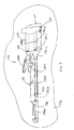
- loading and unloading device 14 includes a carriage or trolley 34, which is mounted on one or more tracks or rails 36, which are in turn mounted to the deck 38 of vehicle 12.
- Carriage 34 is movably mounted to tracks or rails 36 by a pair of guides (not shown).
- guides 36 may comprise sleeves, such as described in PCT/US2004/001070 published under WO 2004/064698 .
- carriage 34 is configured to engage and releasably couple to the head end of patient support 10 so that patient support 10 may be guided into vehicle 10 by loading and unloading device 14 either manually or pulled into the vehicle by a driver, noted below.
- Arm 40 is adapted to lift the head end of the patient support to allow an attendant to guide patient support 10 onto carriage 34 to couple the patient support to carriage 34 so that when carriage 34 is pushed or retracted into the vehicle, patient support 10 will be guided into the vehicle.
- Arm 40 comprises a generally U-shaped member with two arm portions and a transverse member, with the two arm portions pivotally mounted at their distal or proximate their distal ends to carriage 34.
- arm 40 is pivotally mounted to carriage 34 by an axle or pin 42, which extends through the respective ends of the arm portions and carriage 34 to permit arm 40 to move between a generally horizontal position, such as shown in FIG. 3 , and a downwardly angled or lowered position, such as shown in FIG. 1 , so that patient support 10 can be guided onto arm 40.
- Pin 42 may be extended through bushings mounted in carriage 34 and held in place by conventional mechanisms, such as retaining rings or cotter pins or the like.
- Arm 40 is moved between its generally horizontal position and lowered position by driver 44, such as a linear actuator, including a hydraulic cylinder, which is mounted at one end in carriage 34 and at its opposed end to arm 40.
- driver 44 such as a linear actuator, including a hydraulic cylinder, which is mounted at one end in carriage 34 and at its opposed end to arm 40.
- driver 44 is electrically coupled to and powered by rechargeable power supply 28, which as noted above is recharged when loading and unloading device 14 is fully retracted into the vehicle.
- receiving coil 30a is mounted to the leading end of carriage 34, while transmitting coil 20a is located at or near the proximate end of track 36 so that receiving coil 30a will align with and be in close proximity to coil 20a when carriage 34 is fully retracted on the tracks into the vehicle.
- transmitting coil 20a is located at or near the proximate end of track 36 so that receiving coil 30a will align with and be in close proximity to coil 20a when carriage 34 is fully retracted on the tracks into the vehicle.
- coil 20a when carriage 34 is fully retracted into the vehicle and coil 20a is energized, its magnetic field will generate a magnetic field in coil 30a to thereby wirelessly transmit power to recharging circuit 30 and, hence, can recharge rechargeable power supply 28.
- patient support 10 includes an electrically powered device 46 that is powered by rechargeable power supply 22.
- the electrically powered device is a driver, namely an elevation mechanism, for raising the base 48 of patient support 10 relative to the patient support surface 50, which in a cot is referred to as a litter, so that patient support 10 can be configured in a more compact configuration when being loaded into vehicle 12.
- carriage 34 include a releasable latch 52 which is configured to engage the guide wheel support 54 of patient support 10, which is mounted to the head end of patient support 10.
- a suitable latching device is described in U.S. Pat. No. 6,796,757 , which is commonly assigned to Stryker Corporation of Kalamazoo, Mich.
- Guide wheel support 54 supports a wheel or bearing 56 that supports the head end of the patient support 10 on the vehicle deck when patient support 10 is inserted into the vehicle, as would be understood by those skilled in the art.
- arm 40 may include a guide wheel 58, which rides on deck 38 to support arm 40 when arm 40 is in its horizontal orientation. Further, to facilitate manual removal or retraction of the patient support from the vehicle, arm 40 may also include a handle 60 at or proximate its distal end.
- coil 24a is located beneath patient support surface 50a of patient support 10 and, as previously noted, at the foot end 26 of patient support 10. Further, coil 24a is positioned so that when patient support 10 is fully inserted into the vehicle and carriage 34 is fully retracted in the vehicle along track or tracks 36, coil 24a will align and be in registry and/or close proximity to coil 18a, which is supported adjacent track 36 on deck 38. In this manner, when the patient support is fully inserted in the vehicle both receiving coils (24a and 30a) will align and be in registry and/or close proximity to the respective transmitting coils (18a and 20a).
- either circuit 20 or 30 and 18 or 24 may include an impedance matching circuit to improve the resonant frequency match between the respective circuits, which will improve transmission and hence efficiency of the power transmission, as known to those skilled in the art.
- the impedance matching circuit may include feedback loops that check the resonance of the power supply circuit (18, 20) and of the receiving circuit (24, 30) so the impedance of the power supply circuit can be adjusted.
- the feedback loop(s) may provide a dynamic circuit that seeks resonance between the two circuits.
- the power circuit can automatically adjust the frequency of the applied current to the transmitting coil to maintain the frequency resonant with the frequency of the receiving circuit, such as described in EP0700574B1 .
- coil 24a may be used to wirelessly transmit data from patient support 10 to vehicle 12 through induction.
- modulated data signals may be transmitted to coil 24a, which can then wirelessly transmit the data signal to the receiving coil using induction, in this case coil 18a, which generates a reception signal.
- the reception signal is then demodulated by a demodulator.
- the demodulator then may transmit the signal to a processor or storage device, where it can be processed or stored for later use.
- power management data may be transmitted from patient support 10 to vehicle 12.
- Patient support 10 may include a storage device, for example, for storing data relative to the charging and using of rechargeable power supply 22. This data may be stored on the power supply or battery or on the charger.
- Power management data may include, for example, the number of times the battery is charged and the length of use of the battery, which data may be processed for evaluation or stored for later evaluation. Therefore, in this application, the receiving coil at the patient support becomes a transmitting coil for transmitting the data to a receiving coil, for example coil 18a, which then becomes a receiving coil.
- Other data that may be transmitted includes the identification of the patient support or data related to the patient.
- the patient support may incorporate an RFID tag, which identifies the type of patient support, and an RFID reader may be provided on the loading and unloading device so that the loader will recognize the patient support and, for example, know when to actuate the linear actuator to lift the head end of the patient support and how high, for example.
- the identification of the patient support may be transmitted to the vehicle using data transmission by induction rather than RF transmission in a similar manner noted above.
- Patient data that may be transmitted may include patient weight.
- patient support 10 may incorporate load cells, which are coupled to an onboard processor that determines the weight of the patient based in the signals from the load cells.
- This data may be displayed at the patient support, for example, by a LCD display or other types of displays, so that the EMS personnel can determine the correct dosage of a medicine or treatment for example.
- This data similarly can be transmitted from patient support 10 to the storage device on the vehicle, which data can then be stored or processed for later use.
- the data may be inductively transmitted to a storage device on a handheld device (e.g. for an EMT or for EMS services) that includes a receiving coil that is in communication with the data storage device in the handheld device.
- a handheld device e.g. for an EMT or for EMS services
- a receiving coil that is in communication with the data storage device in the handheld device.
- the data in the storage device in either the vehicle or the handheld device may be transmitted, for example, wirelessly to a hospital storage device, including to a patient database.
- the transmission of the data may be made directly between the patient support coil (24a) and a hospital receiving coil when the patient support is delivered to the hospital, with the hospital receiving coil in communication with the hospital storage device.
- frequency-shift keying techniques may be used to minimize the disturbance on the power transmission, such as described in EP0700574B1 .
- driver 44 and 46 other drivers and/or other electrically power devices may be powered by rechargeable power supplies 22 and 28.
- loading and unloading device 14 may incorporate a driver to move carriage relative to the tracks under power to thereby pull or push the patient support relative to the deck.
- patient support 10 may include a fifth wheel to power the patient support, which may also be powered by rechargeable power supply 22 when patient support 10 is being maneuvered through a hospital or at an accident site or the like.
- electrically powered accessories mounted at patient support 10 may also be powered by rechargeable power supply 22.
- the power demand on the rechargeable power supply 22 can be significant; hence, the inductive recharging system of the present invention may significantly prolong the life of the power supply 22, as well as, power supply 28.
- the inductive recharging system of the present invention may significantly prolong the life of the power supply 22, as well as, power supply 28.
- no direct physical contact between the two electrical circuits occurs, which reduces the risk of electrical shock to the patient or the caregiver.
- electrical connectors repetitive coupling and decoupling can cause wear and tear on the connections.
- electrical connections require greater precision in the alignment between the connectors.
- patient support 10 may be secured in the vehicle using other fastening systems.
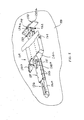
- FIGS. 4-9 another embodiment of a patient support or cot fastening system is illustrated, which comprises a loading and unloading device 114 that is of similar construction to loading and unloading device 14 of the first embodiment and may incorporate a rechargeable power supply and recharging circuit described in reference to the first embodiment.
- a rechargeable power supply and recharging circuit described in reference to the first embodiment.
- Device 114 includes a carriage or trolley 134 that is mounted on track 136, which is in turn mounted to the deck 138 of a vehicle.
- track 136 comprises a rectangular tubular track with opposed guide surfaces 136a for guiding carriage 134.
- Carriage 134 is movably mounted on track 136 for linear movement along track 136 by an intermediate elongate member 135, such as an inverted, generally channel-shaped member.
- Intermediate member 135 includes a plurality of bearing assemblies 135a, for example a plurality of vertically oriented rollers, that engage sides 136a of track 136 and guide member 135, as well as carriage 134, along track 136.
- rollers or bearings are mounted in member 135 between upper and lower inwardly extending flanges by fasteners 135b.
- Intermediate elongate member 135 also includes a second plurality of bearings 135c, such as wheels or rollers, mounted in the channel-shaped member for engaging deck 138 to thereby provide vertical support to member 135 and carriage 134 as they moves along track 136.
- Carriage 134 similarly comprises an inverted, generally channel-shaped member and also includes a plurality of bearing assemblies 134a, which are similarly secured between inwardly extending flanges by fasteners 134b and that engage opposed sides 135d of member 135 so that carriage 134 is movably mounted to member 135.
- carriage 134 and member 135 form a nested rail arrangement in which member 135 can be extended from track 136, and carriage 134 can be extended from member 135 beyond the end of track 136 to extend carriage 134 further from the vehicle, for example, than the first embodiment.
- device 114 includes a pair of pivotal arms 140a and 140b, which are pivotally mounted to carriage 134 and which are moved between a raised or inclined position, shown for example in FIG. 7 , and a lowered position shown in FIG. 4 when carriage 134 is fully extended from the vehicle for loading or unloading patient support 10 into or from the vehicle.
- arms 140a and 140b are commonly mounted to or formed on a base 140c, which is pivotally mounted to carriage 134 by a pair of hinges 142.
- Base 140c optionally includes one or more bearings or rollers 140d, which support base 140a on deck 138 when carriage 134 is retracted into the vehicle.
- arms 140a and 140b also optionally include handles 141 similar to the previous embodiment.
- Arms 140a and 140b are pivoted by at least one actuator housed in carriage 134, which is mounted on one end to base 140c and mounted at its other end to carriage 134.
- actuator housed in carriage 134
- arms 140a and 140b will be lowered relative to carriage 134, and when the actuator is extended the arms will be raised back to their raised or inclined position illustrated in FIG. 7 .
- loading and unloading device 114 operates in a similar manner as device 14 but has an extended range of motion.
- stop assembly 150 is secured to deck 138 at the terminal end of track 136 and extends transversely relative to track 136 so that when carriage 134 is fully retracted into the vehicle, carriage 134 will be in close proximity if not abut stop assembly 150.
- stop assembly 150 may comprise a housing 150a formed from a member having a similar cross-section to carriage 134, e.g.
- stop assembly 150 may house the transmitting circuit described in reference to the previous embodiment in housing 150a.
- stop assembly 150 optionally includes a projecting stop member 152, which is aligned with member 135 so that member 135 will be spaced from stop assembly 150 when fully retracted along track 136, though carriage 134 will be in close proximity if not abut housing 150a.
- stop assembly 150 also may include a locking mechanism 154 that includes a spring biased latch 154a with a switch, which is located such that carriage 134 will initially compress the latch and close the switch, when carriage 134 is retracted and moved toward the stop assembly housing 150a, but once fully retracted will allow the latch to return to its pre-compressed position and engage carriage 134.
- latch 154a will engage carriage 134 to thereby locking the carriage 134 and arms 140 in their fully retracted position.
- the switch may be used to trigger the recharging of the rechargeable power supply located in carriage 134 and/or provide a signal of when the loading device is in its retracted position in the vehicle.
- carriage 134 may be used to power the actuator that raises or lowers arms 140a and 140b.
- carriage 134 may include a driver to move carriage 134 relative to member 135 and/or relative to track 136, which may also be powered by the carriage's on board rechargeable power supply.
- loading and unloading device 114 similarly includes at least one latch 160 for fastening the patient support 10 to carriage 134.
- latches 160 are mounted to the opposed sides of carriage 134, which are adapted to releasably engage the head end wheel or bearing supports, described in reference to the first embodiment, which are mounted to the head end of the patient support 10 to facilitate loading of the patient support into the vehicle.
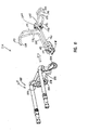
- Cot fastening system 214 comprises an "antler" system with a center yoke 278 and a forward yoke 280. Both yokes 278, 280 are mounted to the ambulance cargo area floor, with a centerline of the antler system 214 aligned in the foreaft direction of the ambulance.
- the center yoke 278 is formed from two rods 282, 283 arranged as mirror images about the centerline of the antler system 276.
- Each rod 282, 283 includes a longitudinal segment 284, 285 and an outwardly divergent segment 286, 287, each outwardly divergent segment 286, 287 rising to a rearwardly directed hook or "ear" 288, 289.
- the forward yoke 280 includes a central segment 290 secured to the ambulance cargo floor and two outwardly divergent arms 291, 292. The arms each terminate in an "ear" 293, 294 that is joined with a respective ear 288, 289 of the center yoke 278.
- a transmitting circuit and transmitting coil 218a Positioned at central segment 290 is a transmitting circuit and transmitting coil 218a, which are electrically coupled to a power supply, such as a battery on the vehicle, for wirelessly transmitting power to a rechargeable power supply on support 210.
- support 210 optionally includes a rechargeable power supply and a recharging circuit that is electrically coupled to the rechargeable power supply.
- the rechargeable power supply and recharging circuit are located at the head end of the patient support 210 so that when patient support 210 is fully loaded into the vehicle, the recharging circuit receiving coil will be aligned with central segment 290 and further with transmitting coil 218a of the transmitting circuit.
- the present invention provides a power system that eliminates the need for direct electrical connectors and reduces the concern for battery management, while enhancing safety.
- the loading and unloading device of the present invention may provide a greater range of motion and extension from the vehicle than heretofore known to further facilitate the loading and unloading of the patient support from a vehicle equipped with the loading and unloading device.
Landscapes
- Health & Medical Sciences (AREA)
- Public Health (AREA)
- Life Sciences & Earth Sciences (AREA)
- Animal Behavior & Ethology (AREA)
- General Health & Medical Sciences (AREA)
- Veterinary Medicine (AREA)
- Charge And Discharge Circuits For Batteries Or The Like (AREA)
- Accommodation For Nursing Or Treatment Tables (AREA)
- Electrotherapy Devices (AREA)
Claims (9)
- Procédé d'alimentation électrique d'un support de patient (10) dans un véhicule comportant :l'étape consistant à mettre en oeuvre un support de patient (10) ;l'étape consistant à monter un bloc d'alimentation électrique rechargeable (22) placé sur le support de patient au niveau du support de patient (10) ;l'étape consistant à mettre en oeuvre un circuit de recharge (24) placé sur le support de patient ;l'étape consistant à effectuer le couplage électrique du circuit de recharge (24) placé sur le support de patient sur le bloc d'alimentation électrique rechargeable (22) placé sur le support de patient ; etl'étape consistant à transmettre sans fil une alimentation électrique au circuit de recharge (24) placé sur le support de patient pour de ce fait recharger le bloc d'alimentation électrique rechargeable (22) placé sur le support de patient au niveau du support de patient (10).
- Procédé d'alimentation électrique d'un support de patient (10) selon la revendication 1, comportant par ailleurs l'étape consistant à mettre en oeuvre un véhicule comportant un bloc d'alimentation électrique (16a) embarqué dans le véhicule, l'étape consistant à charger le support de patient (10) dans le véhicule, et l'étape consistant à transmettre sans fil une alimentation électrique au circuit de recharge (24) placé sur le support de patient en provenance du bloc d'alimentation électrique du véhicule quand le support de patient (10) est chargé dans le véhicule pour de ce fait recharger le bloc d'alimentation électrique rechargeable (22) placé sur le support de patient au niveau du support de patient (10).
- Procédé d'alimentation électrique d'un support de patient (10) selon la revendication 2, comportant par ailleurs l'étape consistant à charger le support de patient (10) dans le véhicule au moyen d'un dispositif de chargement et de déchargement (14), le dispositif de chargement et de déchargement (14) ayant un bloc d'alimentation électrique rechargeable (28) couplé électriquement sur un circuit de recharge (30), et par ailleurs l'étape consistant à transmettre sans fil une alimentation électrique au circuit de recharge (30) du dispositif de chargement et de déchargement (14) en provenance du bloc d'alimentation électrique du véhicule quand le dispositif de chargement et de déchargement (14) est dans une configuration présélectionnée pour de ce fait recharger le bloc d'alimentation électrique rechargeable (28) au niveau du dispositif de chargement et de déchargement (14).
- Procédé selon l'une quelconque des revendications de procédé précédentes, comportant par ailleurs l'étape consistant à générer des données au niveau du support de patient (10), et l'étape consistant à transmettre par induction les données en provenance du support de patient (10).
- Procédé selon la revendication 4, dans lequel les données sont transmises par induction en provenance du support de patient (10) à destination d'un dispositif portatif ou du véhicule.
- Procédé selon la revendication 1, ledit procédé comportant :l'étape consistant à mettre en oeuvre un système d'attache de support de patient ;l'étape consistant à monter un circuit de transmission embarqué dans le véhicule dans un véhicule ; etl'étape consistant à transmettre sans fil une alimentation électrique au circuit de recharge (24) placé sur le support de patient en provenance du circuit de transmission embarqué dans le véhicule pour de ce fait recharger le bloc d'alimentation électrique rechargeable (22) placé sur le support de patient au niveau du support de patient (10).
- Procédé selon la revendication 6, comportant par ailleurs l'étape consistant à mettre en oeuvre un véhicule comportant un bloc d'alimentation électrique (16a) embarqué dans le véhicule, l'étape consistant à positionner le système d'attache de support de patient dans le véhicule, et l'étape consistant à transmettre sans fil une alimentation électrique au circuit de recharge (24) placé sur le support de patient en provenance du bloc d'alimentation électrique (16a) embarqué dans le véhicule du véhicule par le biais du circuit de transmission embarqué dans le véhicule quand le support de patient (10) est dans une position sélectionnée dans le véhicule pour de ce fait recharger le bloc d'alimentation électrique rechargeable (22) placé sur le support de patient au niveau du support de patient (10).
- Procédé selon l'une ou l'autre des revendications 6 ou 7, comportant par ailleurs l'étape consistant à transmettre sans fil une alimentation électrique au circuit de recharge (24) placé sur le support de patient quand le support de patient (10) est assujetti dans le véhicule au moyen du système d'attache de support de patient.
- Procédé selon l'une ou l'autre des revendications 6 ou 7, comportant par ailleurs l'étape consistant à charger ou décharger de manière sélective le support de patient (10) au moyen du système d'attache de support de patient.
Priority Applications (3)
| Application Number | Priority Date | Filing Date | Title |
|---|---|---|---|
| EP18183575.2A EP3453369B1 (fr) | 2007-07-11 | 2008-06-25 | Système de fixation et support de patient alimenté en énergie avec un système d'alimentation par induction |
| EP14189274.5A EP2839819B1 (fr) | 2007-07-11 | 2008-06-25 | Système de fixation et support de patient alimenté en énergie avec un système d'alimentation par induction |
| EP21166823.1A EP3865104B1 (fr) | 2007-07-11 | 2008-06-25 | Système de fixation et support de patient alimenté en énergie avec un système d'alimentation par induction |
Applications Claiming Priority (3)
| Application Number | Priority Date | Filing Date | Title |
|---|---|---|---|
| US94900507P | 2007-07-11 | 2007-07-11 | |
| US12/145,037 US7887113B2 (en) | 2007-07-11 | 2008-06-24 | Powered patient support and fastening system with inductive based power system |
| PCT/US2008/068138 WO2009009296A2 (fr) | 2007-07-11 | 2008-06-25 | Support électrique de patient et système de fixation dote d'un système d'alimentation par induction |
Related Child Applications (3)
| Application Number | Title | Priority Date | Filing Date |
|---|---|---|---|
| EP18183575.2A Division EP3453369B1 (fr) | 2007-07-11 | 2008-06-25 | Système de fixation et support de patient alimenté en énergie avec un système d'alimentation par induction |
| EP21166823.1A Division EP3865104B1 (fr) | 2007-07-11 | 2008-06-25 | Système de fixation et support de patient alimenté en énergie avec un système d'alimentation par induction |
| EP14189274.5A Division EP2839819B1 (fr) | 2007-07-11 | 2008-06-25 | Système de fixation et support de patient alimenté en énergie avec un système d'alimentation par induction |
Publications (3)
| Publication Number | Publication Date |
|---|---|
| EP2178483A2 EP2178483A2 (fr) | 2010-04-28 |
| EP2178483A4 EP2178483A4 (fr) | 2013-01-09 |
| EP2178483B1 true EP2178483B1 (fr) | 2014-10-22 |
Family
ID=40229404
Family Applications (4)
| Application Number | Title | Priority Date | Filing Date |
|---|---|---|---|
| EP18183575.2A Active EP3453369B1 (fr) | 2007-07-11 | 2008-06-25 | Système de fixation et support de patient alimenté en énergie avec un système d'alimentation par induction |
| EP21166823.1A Active EP3865104B1 (fr) | 2007-07-11 | 2008-06-25 | Système de fixation et support de patient alimenté en énergie avec un système d'alimentation par induction |
| EP14189274.5A Active EP2839819B1 (fr) | 2007-07-11 | 2008-06-25 | Système de fixation et support de patient alimenté en énergie avec un système d'alimentation par induction |
| EP08771893.8A Active EP2178483B1 (fr) | 2007-07-11 | 2008-06-25 | Support électrique de patient et système de fixation dote d'un système d'alimentation par induction |
Family Applications Before (3)
| Application Number | Title | Priority Date | Filing Date |
|---|---|---|---|
| EP18183575.2A Active EP3453369B1 (fr) | 2007-07-11 | 2008-06-25 | Système de fixation et support de patient alimenté en énergie avec un système d'alimentation par induction |
| EP21166823.1A Active EP3865104B1 (fr) | 2007-07-11 | 2008-06-25 | Système de fixation et support de patient alimenté en énergie avec un système d'alimentation par induction |
| EP14189274.5A Active EP2839819B1 (fr) | 2007-07-11 | 2008-06-25 | Système de fixation et support de patient alimenté en énergie avec un système d'alimentation par induction |
Country Status (6)
| Country | Link |
|---|---|
| US (1) | US7887113B2 (fr) |
| EP (4) | EP3453369B1 (fr) |
| AU (1) | AU2008275416B2 (fr) |
| CA (1) | CA2693661A1 (fr) |
| DK (2) | DK3453369T3 (fr) |
| WO (1) | WO2009009296A2 (fr) |
Cited By (1)
| Publication number | Priority date | Publication date | Assignee | Title |
|---|---|---|---|---|
| US11957632B2 (en) | 2020-10-02 | 2024-04-16 | Hill-Rom Services, Inc. | Wirelessly charged patient support apparatus system |
Families Citing this family (58)
| Publication number | Priority date | Publication date | Assignee | Title |
|---|---|---|---|---|
| EP2384728B1 (fr) * | 2004-06-30 | 2012-08-22 | Ferno-Washington, Inc. | Système de chargement et de fixation de civière |
| ITBO20050770A1 (it) * | 2005-12-16 | 2007-06-17 | Ferno Washington Italia Srl | Dispositivo di caricamento assistito per una barella |
| US8555433B2 (en) * | 2005-12-16 | 2013-10-15 | Ferno-Washington, Inc. | Devices for the assisted loading of a stretcher |
| US8539624B2 (en) | 2006-05-31 | 2013-09-24 | Gentherm Incorporated | Structure based fluid distribution system |
| US8864205B2 (en) | 2006-06-28 | 2014-10-21 | Stryker Corporation | Patient support with wireless data and/or energy transfer |
| AU2008216990C1 (en) * | 2007-10-16 | 2015-02-19 | Dhs Pty Ltd | Stretcher loading assembly |
| US20090211026A1 (en) * | 2008-02-26 | 2009-08-27 | Robert Schoff | Medical transport safety apparatus with lighting system |
| US20090272953A1 (en) * | 2008-04-30 | 2009-11-05 | Roland Wolf | Lift apparatus |
| JP5258521B2 (ja) * | 2008-11-14 | 2013-08-07 | トヨタ自動車株式会社 | 給電システム |
| AU2013204300A1 (en) * | 2009-10-02 | 2013-05-09 | Stryker Corporation | Ambulance Cot and Loading and Unloading System |
| WO2011041170A2 (fr) * | 2009-10-02 | 2011-04-07 | Stryker Corporation | Civière d'ambulance et système de chargement et de déchargement |
| ES2412012B1 (es) * | 2010-02-22 | 2015-05-04 | Am General Llc | Dispositivo de carga para un vehículo |
| US9375374B2 (en) | 2010-04-09 | 2016-06-28 | Hill-Rom Services, Inc. | Siderail power communication interface |
| FR2959661B1 (fr) * | 2010-05-07 | 2013-04-12 | Decide Life Internat Sa | Chariot de soins medicalise |
| DE102011005646A1 (de) * | 2011-03-16 | 2012-09-20 | Hilti Aktiengesellschaft | Mobiles Ladegerät |
| US8499384B2 (en) | 2011-03-17 | 2013-08-06 | Hill-Rom Services, Inc. | Pendant assembly with removable tether |
| IL219498A0 (en) * | 2012-04-30 | 2012-07-31 | Bar Buzaglo Hana | Infant inflatable seat |
| US9451723B2 (en) | 2012-07-06 | 2016-09-20 | Gentherm Incorporated | System and method for thermoelectrically cooling inductive charging assemblies |
| US10504132B2 (en) | 2012-11-27 | 2019-12-10 | American Express Travel Related Services Company, Inc. | Dynamic rewards program |
| US9510981B2 (en) | 2013-03-14 | 2016-12-06 | Stryker Corporation | Reconfigurable transport apparatus |
| US9486373B2 (en) | 2013-03-14 | 2016-11-08 | Stryker Corporation | Reconfigurable patient support |
| CA2865739C (fr) | 2013-09-30 | 2018-12-04 | Norman R. Byrne | Energie sans fil pour objets portatifs |
| CA2865457C (fr) | 2013-09-30 | 2019-01-22 | Norman R. Byrne | Articles avec surfaces de charge electriques |
| DE112014005563T5 (de) | 2013-12-05 | 2016-11-24 | Gentherm Incorporated | Systeme und Verfahren für klimatisierte Sitze |
| US9463126B2 (en) | 2014-03-11 | 2016-10-11 | Hill-Rom Services, Inc. | Caregiver universal remote cart for patient bed control |
| WO2015191819A1 (fr) * | 2014-06-11 | 2015-12-17 | Gentherm Incorporated | Système et procédé de régulation de climatisation de bureau |
| US9943453B2 (en) | 2014-06-20 | 2018-04-17 | Stryker Corporation | Overhead loading device |
| US10028868B2 (en) * | 2014-07-08 | 2018-07-24 | Stryker Corporation | Loading and unloading apparatus |
| BR112017003146A2 (pt) * | 2014-08-19 | 2017-11-28 | Ferno Washington | sistema de fixação de berço, e, método para fixar e reter um berço de emergência que tem rodas, um primeiro dispositivo de fixação e um segundo dispositivo de fixação. |
| US10181735B2 (en) | 2015-03-11 | 2019-01-15 | Norman R. Byrne | Portable electrical power unit |
| US10058464B2 (en) | 2015-10-23 | 2018-08-28 | Stryker Corporation | Cot fastening system |
| FR3043322A1 (fr) * | 2015-11-10 | 2017-05-12 | Groupe Gifa | Vehicule d'intervention connectee dotee d'un moyen de communication embarque |
| MX383881B (es) | 2016-03-11 | 2025-03-14 | Norman R Byrne | Estación de carga para montar en muebles. |
| US10358268B2 (en) | 2016-04-08 | 2019-07-23 | Stryker Corporation | Opening cover |
| US10245192B2 (en) * | 2016-04-13 | 2019-04-02 | Bobby Allan Burkeen | Extendable and retractable gurney |
| CA2969439C (fr) | 2016-06-03 | 2022-11-01 | Norman R. Byrne | Resonateurs installes en surface destines a une alimentation sans fil |
| ES2620954B2 (es) * | 2016-12-23 | 2018-04-18 | Universidad De Alicante | Bancada inteligente para ambulancias |
| AU2017100274A4 (en) * | 2017-03-08 | 2017-04-27 | Helimods Pty Ltd | The Powered Aero Loader lifts, at a press of a button, Stryker Power Pro XT and Stryker Performance Pro (with adaption) stretchers and allows these stretchers to be secured into the aircraft. The Powered Aero Loaders aircraft interface specifically distributes loads generated by the stretcher systems during loading, unloading and inflight to allow for safe carriage in aircraft. |
| US10980689B2 (en) | 2017-07-14 | 2021-04-20 | Stryker Corporation | Patient support apparatuses with personal electronic device charging |
| MX387762B (es) | 2017-07-24 | 2025-03-18 | Norman R Byrne | Estacion de carga electrica montada en muebles |
| US11529272B2 (en) * | 2017-08-01 | 2022-12-20 | Uriah S. Akers, Jr. | Power lift |
| US10797524B2 (en) | 2017-10-24 | 2020-10-06 | Stryker Corporation | Techniques for power transfer through wheels of a patient support apparatus |
| US11139666B2 (en) | 2017-10-24 | 2021-10-05 | Stryker Corporation | Energy harvesting and propulsion assistance techniques for a patient support apparatus |
| US10910888B2 (en) | 2017-10-24 | 2021-02-02 | Stryker Corporation | Power transfer system with patient transport apparatus and power transfer device to transfer power to the patient transport apparatus |
| US11389357B2 (en) | 2017-10-24 | 2022-07-19 | Stryker Corporation | Energy storage device management for a patient support apparatus |
| US11394252B2 (en) | 2017-10-24 | 2022-07-19 | Stryker Corporation | Power transfer system with patient support apparatus and power transfer device to transfer power to the patient support apparatus |
| US10940068B2 (en) * | 2017-12-21 | 2021-03-09 | Stryker Corporation | Patient support apparatus with portable charging device |
| US11896535B1 (en) | 2018-04-23 | 2024-02-13 | Uriah S. Akers, Jr. | Power lift |
| US10912687B2 (en) * | 2018-09-24 | 2021-02-09 | Valeda Company, Llc | Gurney restraint system |
| AU2019275614B2 (en) * | 2018-12-18 | 2025-08-21 | Stryker Corporation | Track assembly |
| FR3100710B1 (fr) | 2019-09-13 | 2021-08-06 | Cdc Group | Recepteur de chargement et d’extraction motorises d’un chariot portant un brancard et ambulance associee |
| AU2020102735B4 (en) * | 2019-10-15 | 2021-09-30 | Five Rings Aerospace Pty Ltd | Stretcher |
| EP3827799A1 (fr) * | 2019-11-29 | 2021-06-02 | Siemens Healthcare GmbH | Véhicule ambulance et procédé de fourniture d'un véhicule ambulance |
| US11890234B2 (en) | 2019-12-30 | 2024-02-06 | Stryker Corporation | Patient transport apparatus with crash detection |
| US12325333B2 (en) * | 2020-05-06 | 2025-06-10 | Demers, Ambulance Manufacturer Inc./Demers, Manufacturier D'ambulances Inc. | Multi-pivot seat base assembly |
| EP4391982B1 (fr) | 2021-08-26 | 2025-07-02 | Stryker Corporation | Systèmes de support de patient avec architecture de transfert d'énergie |
| IT202100032378A1 (it) * | 2021-12-23 | 2023-06-23 | Spencer Italia Srl | Supporto barella da installare in vani sanitari di autoambulanze |
| US12060148B2 (en) | 2022-08-16 | 2024-08-13 | Honeywell International Inc. | Ground resonance detection and warning system and method |
Family Cites Families (29)
| Publication number | Priority date | Publication date | Assignee | Title |
|---|---|---|---|---|
| US2456024A (en) * | 1945-03-05 | 1948-12-14 | Du Pont | Foldable stretcher carrier for ambulances |
| DE1566422C3 (de) * | 1967-03-25 | 1974-01-31 | Binz & Co, 7073 Lorch | In drei Längsstellungen einstellbare Tragenbühne |
| US4052097A (en) * | 1976-04-19 | 1977-10-04 | Burt Weil | Cart for high deck ambulances |
| US4097941A (en) * | 1977-05-17 | 1978-07-04 | Merkel Jerome L | Emergency cot with spring-biased retractable wheel carriage |
| US4273374A (en) * | 1979-01-03 | 1981-06-16 | Portman Stanley J | Anchoring device for intravenous bottle holder |
| US4584989A (en) * | 1984-12-20 | 1986-04-29 | Rosemarie Stith | Life support stretcher bed |
| GB2203999A (en) * | 1987-03-11 | 1988-11-02 | Macclesfield Motor Bodies | Vehicle loading platform |
| DE4138319A1 (de) * | 1991-11-21 | 1993-05-27 | Stierlen Maquet Ag | Operationstisch mit abnehmbar gehaltener patientenlagerflaeche |
| GB9310545D0 (en) | 1993-05-21 | 1993-07-07 | Era Patents Ltd | Power coupling |
| IT1261133B (it) * | 1993-12-23 | 1996-05-09 | Gf Gestioni Ind Srl | Elicottero per interventi di pronto soccorso e trasporto feriti |
| US5537700A (en) | 1994-04-19 | 1996-07-23 | Stryker Corporation | Emergency stretcher with X-frame support |
| US5755479A (en) * | 1995-03-02 | 1998-05-26 | Theradynamics Corporation | Umbilicus system for delivering medical services |
| US5697110A (en) * | 1995-12-01 | 1997-12-16 | Patient Easy Care Products, Inc. | Control panel for a patient transporter |
| WO1998004228A1 (fr) * | 1996-07-26 | 1998-02-05 | Huntleigh Technology Plc | Plate-forme de chargement pour civiere |
| US6125485A (en) | 1998-06-22 | 2000-10-03 | Stryker Corporation | Ambulance cot |
| JP2000108770A (ja) * | 1998-10-02 | 2000-04-18 | Central Motor Co Ltd | 自動車用車椅子収納装置 |
| IT248244Y1 (it) * | 1999-03-05 | 2002-12-16 | Stem Srl | Attrezzo per il carico delle barelle su ambulanze. |
| EP1698314B1 (fr) | 2000-03-17 | 2010-04-21 | Stryker Corporation | Civière |
| US6796757B1 (en) | 2000-10-27 | 2004-09-28 | Stryker Corporation | Ambulance cot lock |
| JP4015805B2 (ja) * | 2000-11-17 | 2007-11-28 | 新明和リビテック株式会社 | 救急車両におけるストレッチャの移載装置 |
| AU2003248014B2 (en) * | 2002-09-26 | 2008-11-06 | Ferno Australia Pty Ltd | Roll-in Cot |
| JP4676954B2 (ja) * | 2003-01-15 | 2011-04-27 | ストライカー コーポレイション ア コーポレイション オブ ザ ステート オブ ミシガン | 救急用簡易ベッドの積み降ろし装置 |
| US20060225203A1 (en) * | 2003-03-31 | 2006-10-12 | Shinmaywa Industries, Ltd | Stretcher, stretcher system and method for using the system |
| US20040202533A1 (en) * | 2003-04-08 | 2004-10-14 | Haire A. Ralph | Bed containment system for vehicles |
| US7100224B2 (en) | 2004-03-19 | 2006-09-05 | Stryker Corporation | Ambulance cot load wheel assisting device |
| EP2384728B1 (fr) * | 2004-06-30 | 2012-08-22 | Ferno-Washington, Inc. | Système de chargement et de fixation de civière |
| US7287794B2 (en) | 2004-08-23 | 2007-10-30 | Ferno-Washington, Inc. | Arresting device of a cot fastening system |
| US7398571B2 (en) * | 2004-09-24 | 2008-07-15 | Stryker Corporation | Ambulance cot and hydraulic elevating mechanism therefor |
| WO2008003027A2 (fr) * | 2006-06-28 | 2008-01-03 | Stryker Corporation | Support de patient |
-
2008
- 2008-06-24 US US12/145,037 patent/US7887113B2/en active Active
- 2008-06-25 EP EP18183575.2A patent/EP3453369B1/fr active Active
- 2008-06-25 WO PCT/US2008/068138 patent/WO2009009296A2/fr not_active Ceased
- 2008-06-25 CA CA2693661A patent/CA2693661A1/fr not_active Abandoned
- 2008-06-25 EP EP21166823.1A patent/EP3865104B1/fr active Active
- 2008-06-25 EP EP14189274.5A patent/EP2839819B1/fr active Active
- 2008-06-25 DK DK18183575.2T patent/DK3453369T3/da active
- 2008-06-25 EP EP08771893.8A patent/EP2178483B1/fr active Active
- 2008-06-25 AU AU2008275416A patent/AU2008275416B2/en not_active Ceased
- 2008-06-25 DK DK21166823.1T patent/DK3865104T3/da active
Cited By (1)
| Publication number | Priority date | Publication date | Assignee | Title |
|---|---|---|---|---|
| US11957632B2 (en) | 2020-10-02 | 2024-04-16 | Hill-Rom Services, Inc. | Wirelessly charged patient support apparatus system |
Also Published As
| Publication number | Publication date |
|---|---|
| AU2008275416B2 (en) | 2014-05-22 |
| EP2178483A2 (fr) | 2010-04-28 |
| DK3453369T3 (da) | 2021-04-26 |
| EP3453369B1 (fr) | 2021-04-07 |
| WO2009009296A3 (fr) | 2009-03-12 |
| EP2178483A4 (fr) | 2013-01-09 |
| EP3865104B1 (fr) | 2023-07-19 |
| EP2839819A1 (fr) | 2015-02-25 |
| EP3453369A2 (fr) | 2019-03-13 |
| CA2693661A1 (fr) | 2009-01-15 |
| EP3453369A3 (fr) | 2019-05-22 |
| WO2009009296A2 (fr) | 2009-01-15 |
| EP3865104A1 (fr) | 2021-08-18 |
| AU2008275416A1 (en) | 2009-01-15 |
| DK3865104T3 (da) | 2023-10-09 |
| EP2839819B1 (fr) | 2018-07-18 |
| US20090015027A1 (en) | 2009-01-15 |
| US7887113B2 (en) | 2011-02-15 |
Similar Documents
| Publication | Publication Date | Title |
|---|---|---|
| EP2178483B1 (fr) | Support électrique de patient et système de fixation dote d'un système d'alimentation par induction | |
| US20200155393A1 (en) | Patient support with energy transfer | |
| AU2020277119B2 (en) | Reconfigurable transport apparatus | |
| EP0651619B1 (fr) | Lit d'hopital et materiel medical sur roues et a emboitement | |
| EP1089672B1 (fr) | Appareil utile pour transporter un animal et son procede d'utilisation | |
| EP2228045B1 (fr) | Dispositif de chargement et de déchargement de civière d'ambulance | |
| EP3362020B1 (fr) | Système d'imagerie comprennant un chariot-brancard pour patient compatible avec une irm | |
| WO1990003157A1 (fr) | Systeme de transport d'appareils portatifs de soins aux malades | |
| AU2014203039B2 (en) | Powered patient support and fastening system with induction based power system | |
| CN222075443U (zh) | 一种患者转运车 | |
| AU2020102735B4 (en) | Stretcher | |
| EP2033610A2 (fr) | Système de transport incluant une unité de commande | |
| CN215385246U (zh) | 一种用于急救的病人转运平车 | |
| US20260090937A1 (en) | Medical bed apparatuses, medical systems and medical methods | |
| CN117838447A (zh) | 一种患者转运车及患者转运方法 | |
| TR2023001103U5 (tr) | Hastanin yatağina alinmasini sağlayan sedye tasarimi |
Legal Events
| Date | Code | Title | Description |
|---|---|---|---|
| PUAI | Public reference made under article 153(3) epc to a published international application that has entered the european phase |
Free format text: ORIGINAL CODE: 0009012 |
|
| 17P | Request for examination filed |
Effective date: 20100211 |
|
| AK | Designated contracting states |
Kind code of ref document: A2 Designated state(s): AT BE BG CH CY CZ DE DK EE ES FI FR GB GR HR HU IE IS IT LI LT LU LV MC MT NL NO PL PT RO SE SI SK TR |
|
| AX | Request for extension of the european patent |
Extension state: AL BA MK RS |
|
| DAX | Request for extension of the european patent (deleted) | ||
| A4 | Supplementary search report drawn up and despatched |
Effective date: 20121212 |
|
| RIC1 | Information provided on ipc code assigned before grant |
Ipc: A61G 3/02 20060101AFI20121206BHEP Ipc: A61G 1/06 20060101ALI20121206BHEP Ipc: A61G 3/08 20060101ALI20121206BHEP Ipc: A61G 1/02 20060101ALI20121206BHEP |
|
| GRAP | Despatch of communication of intention to grant a patent |
Free format text: ORIGINAL CODE: EPIDOSNIGR1 |
|
| INTG | Intention to grant announced |
Effective date: 20140429 |
|
| GRAS | Grant fee paid |
Free format text: ORIGINAL CODE: EPIDOSNIGR3 |
|
| GRAA | (expected) grant |
Free format text: ORIGINAL CODE: 0009210 |
|
| AK | Designated contracting states |
Kind code of ref document: B1 Designated state(s): AT BE BG CH CY CZ DE DK EE ES FI FR GB GR HR HU IE IS IT LI LT LU LV MC MT NL NO PL PT RO SE SI SK TR |
|
| REG | Reference to a national code |
Ref country code: GB Ref legal event code: FG4D |
|
| REG | Reference to a national code |
Ref country code: CH Ref legal event code: EP |
|
| REG | Reference to a national code |
Ref country code: AT Ref legal event code: REF Ref document number: 692247 Country of ref document: AT Kind code of ref document: T Effective date: 20141115 |
|
| REG | Reference to a national code |
Ref country code: IE Ref legal event code: FG4D |
|
| REG | Reference to a national code |
Ref country code: DE Ref legal event code: R096 Ref document number: 602008035011 Country of ref document: DE Effective date: 20141204 |
|
| REG | Reference to a national code |
Ref country code: NL Ref legal event code: VDEP Effective date: 20141022 |
|
| REG | Reference to a national code |
Ref country code: AT Ref legal event code: MK05 Ref document number: 692247 Country of ref document: AT Kind code of ref document: T Effective date: 20141022 |
|
| REG | Reference to a national code |
Ref country code: LT Ref legal event code: MG4D |
|
| PG25 | Lapsed in a contracting state [announced via postgrant information from national office to epo] |
Ref country code: FI Free format text: LAPSE BECAUSE OF FAILURE TO SUBMIT A TRANSLATION OF THE DESCRIPTION OR TO PAY THE FEE WITHIN THE PRESCRIBED TIME-LIMIT Effective date: 20141022 Ref country code: LT Free format text: LAPSE BECAUSE OF FAILURE TO SUBMIT A TRANSLATION OF THE DESCRIPTION OR TO PAY THE FEE WITHIN THE PRESCRIBED TIME-LIMIT Effective date: 20141022 Ref country code: IS Free format text: LAPSE BECAUSE OF FAILURE TO SUBMIT A TRANSLATION OF THE DESCRIPTION OR TO PAY THE FEE WITHIN THE PRESCRIBED TIME-LIMIT Effective date: 20150222 Ref country code: NO Free format text: LAPSE BECAUSE OF FAILURE TO SUBMIT A TRANSLATION OF THE DESCRIPTION OR TO PAY THE FEE WITHIN THE PRESCRIBED TIME-LIMIT Effective date: 20150122 Ref country code: NL Free format text: LAPSE BECAUSE OF FAILURE TO SUBMIT A TRANSLATION OF THE DESCRIPTION OR TO PAY THE FEE WITHIN THE PRESCRIBED TIME-LIMIT Effective date: 20141022 Ref country code: ES Free format text: LAPSE BECAUSE OF FAILURE TO SUBMIT A TRANSLATION OF THE DESCRIPTION OR TO PAY THE FEE WITHIN THE PRESCRIBED TIME-LIMIT Effective date: 20141022 Ref country code: PT Free format text: LAPSE BECAUSE OF FAILURE TO SUBMIT A TRANSLATION OF THE DESCRIPTION OR TO PAY THE FEE WITHIN THE PRESCRIBED TIME-LIMIT Effective date: 20150223 |
|
| PG25 | Lapsed in a contracting state [announced via postgrant information from national office to epo] |
Ref country code: PL Free format text: LAPSE BECAUSE OF FAILURE TO SUBMIT A TRANSLATION OF THE DESCRIPTION OR TO PAY THE FEE WITHIN THE PRESCRIBED TIME-LIMIT Effective date: 20141022 Ref country code: AT Free format text: LAPSE BECAUSE OF FAILURE TO SUBMIT A TRANSLATION OF THE DESCRIPTION OR TO PAY THE FEE WITHIN THE PRESCRIBED TIME-LIMIT Effective date: 20141022 Ref country code: CY Free format text: LAPSE BECAUSE OF FAILURE TO SUBMIT A TRANSLATION OF THE DESCRIPTION OR TO PAY THE FEE WITHIN THE PRESCRIBED TIME-LIMIT Effective date: 20141022 Ref country code: LV Free format text: LAPSE BECAUSE OF FAILURE TO SUBMIT A TRANSLATION OF THE DESCRIPTION OR TO PAY THE FEE WITHIN THE PRESCRIBED TIME-LIMIT Effective date: 20141022 Ref country code: GR Free format text: LAPSE BECAUSE OF FAILURE TO SUBMIT A TRANSLATION OF THE DESCRIPTION OR TO PAY THE FEE WITHIN THE PRESCRIBED TIME-LIMIT Effective date: 20150123 Ref country code: SE Free format text: LAPSE BECAUSE OF FAILURE TO SUBMIT A TRANSLATION OF THE DESCRIPTION OR TO PAY THE FEE WITHIN THE PRESCRIBED TIME-LIMIT Effective date: 20141022 Ref country code: HR Free format text: LAPSE BECAUSE OF FAILURE TO SUBMIT A TRANSLATION OF THE DESCRIPTION OR TO PAY THE FEE WITHIN THE PRESCRIBED TIME-LIMIT Effective date: 20141022 |
|
| REG | Reference to a national code |
Ref country code: DE Ref legal event code: R097 Ref document number: 602008035011 Country of ref document: DE |
|
| PG25 | Lapsed in a contracting state [announced via postgrant information from national office to epo] |
Ref country code: RO Free format text: LAPSE BECAUSE OF FAILURE TO SUBMIT A TRANSLATION OF THE DESCRIPTION OR TO PAY THE FEE WITHIN THE PRESCRIBED TIME-LIMIT Effective date: 20141022 Ref country code: SK Free format text: LAPSE BECAUSE OF FAILURE TO SUBMIT A TRANSLATION OF THE DESCRIPTION OR TO PAY THE FEE WITHIN THE PRESCRIBED TIME-LIMIT Effective date: 20141022 Ref country code: CZ Free format text: LAPSE BECAUSE OF FAILURE TO SUBMIT A TRANSLATION OF THE DESCRIPTION OR TO PAY THE FEE WITHIN THE PRESCRIBED TIME-LIMIT Effective date: 20141022 Ref country code: EE Free format text: LAPSE BECAUSE OF FAILURE TO SUBMIT A TRANSLATION OF THE DESCRIPTION OR TO PAY THE FEE WITHIN THE PRESCRIBED TIME-LIMIT Effective date: 20141022 Ref country code: DK Free format text: LAPSE BECAUSE OF FAILURE TO SUBMIT A TRANSLATION OF THE DESCRIPTION OR TO PAY THE FEE WITHIN THE PRESCRIBED TIME-LIMIT Effective date: 20141022 |
|
| PLBE | No opposition filed within time limit |
Free format text: ORIGINAL CODE: 0009261 |
|
| STAA | Information on the status of an ep patent application or granted ep patent |
Free format text: STATUS: NO OPPOSITION FILED WITHIN TIME LIMIT |
|
| PG25 | Lapsed in a contracting state [announced via postgrant information from national office to epo] |
Ref country code: IT Free format text: LAPSE BECAUSE OF FAILURE TO SUBMIT A TRANSLATION OF THE DESCRIPTION OR TO PAY THE FEE WITHIN THE PRESCRIBED TIME-LIMIT Effective date: 20141022 |
|
| 26N | No opposition filed |
Effective date: 20150723 |
|
| PG25 | Lapsed in a contracting state [announced via postgrant information from national office to epo] |
Ref country code: MC Free format text: LAPSE BECAUSE OF FAILURE TO SUBMIT A TRANSLATION OF THE DESCRIPTION OR TO PAY THE FEE WITHIN THE PRESCRIBED TIME-LIMIT Effective date: 20141022 |
|
| REG | Reference to a national code |
Ref country code: CH Ref legal event code: PL |
|
| PG25 | Lapsed in a contracting state [announced via postgrant information from national office to epo] |
Ref country code: SI Free format text: LAPSE BECAUSE OF FAILURE TO SUBMIT A TRANSLATION OF THE DESCRIPTION OR TO PAY THE FEE WITHIN THE PRESCRIBED TIME-LIMIT Effective date: 20141022 Ref country code: LU Free format text: LAPSE BECAUSE OF FAILURE TO SUBMIT A TRANSLATION OF THE DESCRIPTION OR TO PAY THE FEE WITHIN THE PRESCRIBED TIME-LIMIT Effective date: 20150625 |
|
| REG | Reference to a national code |
Ref country code: IE Ref legal event code: MM4A |
|
| PG25 | Lapsed in a contracting state [announced via postgrant information from national office to epo] |
Ref country code: IE Free format text: LAPSE BECAUSE OF NON-PAYMENT OF DUE FEES Effective date: 20150625 Ref country code: LI Free format text: LAPSE BECAUSE OF NON-PAYMENT OF DUE FEES Effective date: 20150630 Ref country code: CH Free format text: LAPSE BECAUSE OF NON-PAYMENT OF DUE FEES Effective date: 20150630 |
|
| REG | Reference to a national code |
Ref country code: FR Ref legal event code: PLFP Year of fee payment: 9 |
|
| PG25 | Lapsed in a contracting state [announced via postgrant information from national office to epo] |
Ref country code: MT Free format text: LAPSE BECAUSE OF FAILURE TO SUBMIT A TRANSLATION OF THE DESCRIPTION OR TO PAY THE FEE WITHIN THE PRESCRIBED TIME-LIMIT Effective date: 20141022 |
|
| REG | Reference to a national code |
Ref country code: FR Ref legal event code: PLFP Year of fee payment: 10 |
|
| PG25 | Lapsed in a contracting state [announced via postgrant information from national office to epo] |
Ref country code: HU Free format text: LAPSE BECAUSE OF FAILURE TO SUBMIT A TRANSLATION OF THE DESCRIPTION OR TO PAY THE FEE WITHIN THE PRESCRIBED TIME-LIMIT; INVALID AB INITIO Effective date: 20080625 Ref country code: BG Free format text: LAPSE BECAUSE OF FAILURE TO SUBMIT A TRANSLATION OF THE DESCRIPTION OR TO PAY THE FEE WITHIN THE PRESCRIBED TIME-LIMIT Effective date: 20141022 |
|
| PG25 | Lapsed in a contracting state [announced via postgrant information from national office to epo] |
Ref country code: TR Free format text: LAPSE BECAUSE OF FAILURE TO SUBMIT A TRANSLATION OF THE DESCRIPTION OR TO PAY THE FEE WITHIN THE PRESCRIBED TIME-LIMIT Effective date: 20141022 |
|
| PG25 | Lapsed in a contracting state [announced via postgrant information from national office to epo] |
Ref country code: BE Free format text: LAPSE BECAUSE OF FAILURE TO SUBMIT A TRANSLATION OF THE DESCRIPTION OR TO PAY THE FEE WITHIN THE PRESCRIBED TIME-LIMIT Effective date: 20141022 |
|
| REG | Reference to a national code |
Ref country code: FR Ref legal event code: PLFP Year of fee payment: 11 |
|
| P01 | Opt-out of the competence of the unified patent court (upc) registered |
Effective date: 20230522 |
|
| PGFP | Annual fee paid to national office [announced via postgrant information from national office to epo] |
Ref country code: DE Payment date: 20250402 Year of fee payment: 18 |
|
| PGFP | Annual fee paid to national office [announced via postgrant information from national office to epo] |
Ref country code: GB Payment date: 20250401 Year of fee payment: 18 |
|
| PGFP | Annual fee paid to national office [announced via postgrant information from national office to epo] |
Ref country code: FR Payment date: 20250508 Year of fee payment: 18 |