EP2179217B1 - Dispositif d'éclairage - Google Patents
Dispositif d'éclairage Download PDFInfo
- Publication number
- EP2179217B1 EP2179217B1 EP08785463.4A EP08785463A EP2179217B1 EP 2179217 B1 EP2179217 B1 EP 2179217B1 EP 08785463 A EP08785463 A EP 08785463A EP 2179217 B1 EP2179217 B1 EP 2179217B1
- Authority
- EP
- European Patent Office
- Prior art keywords
- lighting apparatus
- housing
- reflector
- electrically conductive
- electromagnetic radiation
- Prior art date
- Legal status (The legal status is an assumption and is not a legal conclusion. Google has not performed a legal analysis and makes no representation as to the accuracy of the status listed.)
- Active
Links
Images


Classifications
-
- F—MECHANICAL ENGINEERING; LIGHTING; HEATING; WEAPONS; BLASTING
- F21—LIGHTING
- F21V—FUNCTIONAL FEATURES OR DETAILS OF LIGHTING DEVICES OR SYSTEMS THEREOF; STRUCTURAL COMBINATIONS OF LIGHTING DEVICES WITH OTHER ARTICLES, NOT OTHERWISE PROVIDED FOR
- F21V3/00—Globes; Bowls; Cover glasses
- F21V3/04—Globes; Bowls; Cover glasses characterised by materials, surface treatments or coatings
-
- F—MECHANICAL ENGINEERING; LIGHTING; HEATING; WEAPONS; BLASTING
- F21—LIGHTING
- F21S—NON-PORTABLE LIGHTING DEVICES; SYSTEMS THEREOF; VEHICLE LIGHTING DEVICES SPECIALLY ADAPTED FOR VEHICLE EXTERIORS
- F21S41/00—Illuminating devices specially adapted for vehicle exteriors, e.g. headlamps
- F21S41/10—Illuminating devices specially adapted for vehicle exteriors, e.g. headlamps characterised by the light source
- F21S41/14—Illuminating devices specially adapted for vehicle exteriors, e.g. headlamps characterised by the light source characterised by the type of light source
- F21S41/141—Light emitting diodes [LED]
- F21S41/143—Light emitting diodes [LED] the main emission direction of the LED being parallel to the optical axis of the illuminating device
-
- F—MECHANICAL ENGINEERING; LIGHTING; HEATING; WEAPONS; BLASTING
- F21—LIGHTING
- F21S—NON-PORTABLE LIGHTING DEVICES; SYSTEMS THEREOF; VEHICLE LIGHTING DEVICES SPECIALLY ADAPTED FOR VEHICLE EXTERIORS
- F21S41/00—Illuminating devices specially adapted for vehicle exteriors, e.g. headlamps
- F21S41/20—Illuminating devices specially adapted for vehicle exteriors, e.g. headlamps characterised by refractors, transparent cover plates, light guides or filters
- F21S41/25—Projection lenses
- F21S41/275—Lens surfaces, e.g. coatings or surface structures
-
- F—MECHANICAL ENGINEERING; LIGHTING; HEATING; WEAPONS; BLASTING
- F21—LIGHTING
- F21S—NON-PORTABLE LIGHTING DEVICES; SYSTEMS THEREOF; VEHICLE LIGHTING DEVICES SPECIALLY ADAPTED FOR VEHICLE EXTERIORS
- F21S41/00—Illuminating devices specially adapted for vehicle exteriors, e.g. headlamps
- F21S41/30—Illuminating devices specially adapted for vehicle exteriors, e.g. headlamps characterised by reflectors
- F21S41/37—Illuminating devices specially adapted for vehicle exteriors, e.g. headlamps characterised by reflectors characterised by their material, surface treatment or coatings
-
- F—MECHANICAL ENGINEERING; LIGHTING; HEATING; WEAPONS; BLASTING
- F21—LIGHTING
- F21S—NON-PORTABLE LIGHTING DEVICES; SYSTEMS THEREOF; VEHICLE LIGHTING DEVICES SPECIALLY ADAPTED FOR VEHICLE EXTERIORS
- F21S43/00—Signalling devices specially adapted for vehicle exteriors, e.g. brake lamps, direction indicator lights or reversing lights
- F21S43/10—Signalling devices specially adapted for vehicle exteriors, e.g. brake lamps, direction indicator lights or reversing lights characterised by the light source
- F21S43/13—Signalling devices specially adapted for vehicle exteriors, e.g. brake lamps, direction indicator lights or reversing lights characterised by the light source characterised by the type of light source
- F21S43/14—Light emitting diodes [LED]
-
- F—MECHANICAL ENGINEERING; LIGHTING; HEATING; WEAPONS; BLASTING
- F21—LIGHTING
- F21S—NON-PORTABLE LIGHTING DEVICES; SYSTEMS THEREOF; VEHICLE LIGHTING DEVICES SPECIALLY ADAPTED FOR VEHICLE EXTERIORS
- F21S43/00—Signalling devices specially adapted for vehicle exteriors, e.g. brake lamps, direction indicator lights or reversing lights
- F21S43/20—Signalling devices specially adapted for vehicle exteriors, e.g. brake lamps, direction indicator lights or reversing lights characterised by refractors, transparent cover plates, light guides or filters
-
- F—MECHANICAL ENGINEERING; LIGHTING; HEATING; WEAPONS; BLASTING
- F21—LIGHTING
- F21S—NON-PORTABLE LIGHTING DEVICES; SYSTEMS THEREOF; VEHICLE LIGHTING DEVICES SPECIALLY ADAPTED FOR VEHICLE EXTERIORS
- F21S43/00—Signalling devices specially adapted for vehicle exteriors, e.g. brake lamps, direction indicator lights or reversing lights
- F21S43/30—Signalling devices specially adapted for vehicle exteriors, e.g. brake lamps, direction indicator lights or reversing lights characterised by reflectors
- F21S43/33—Signalling devices specially adapted for vehicle exteriors, e.g. brake lamps, direction indicator lights or reversing lights characterised by reflectors characterised by their material, surface treatment or coatings
-
- F—MECHANICAL ENGINEERING; LIGHTING; HEATING; WEAPONS; BLASTING
- F21—LIGHTING
- F21S—NON-PORTABLE LIGHTING DEVICES; SYSTEMS THEREOF; VEHICLE LIGHTING DEVICES SPECIALLY ADAPTED FOR VEHICLE EXTERIORS
- F21S45/00—Arrangements within vehicle lighting devices specially adapted for vehicle exteriors, for purposes other than emission or distribution of light
- F21S45/10—Protection of lighting devices
-
- F—MECHANICAL ENGINEERING; LIGHTING; HEATING; WEAPONS; BLASTING
- F21—LIGHTING
- F21V—FUNCTIONAL FEATURES OR DETAILS OF LIGHTING DEVICES OR SYSTEMS THEREOF; STRUCTURAL COMBINATIONS OF LIGHTING DEVICES WITH OTHER ARTICLES, NOT OTHERWISE PROVIDED FOR
- F21V15/00—Protecting lighting devices from damage
- F21V15/01—Housings, e.g. material or assembling of housing parts
-
- F—MECHANICAL ENGINEERING; LIGHTING; HEATING; WEAPONS; BLASTING
- F21—LIGHTING
- F21V—FUNCTIONAL FEATURES OR DETAILS OF LIGHTING DEVICES OR SYSTEMS THEREOF; STRUCTURAL COMBINATIONS OF LIGHTING DEVICES WITH OTHER ARTICLES, NOT OTHERWISE PROVIDED FOR
- F21V23/00—Arrangement of electric circuit elements in or on lighting devices
- F21V23/02—Arrangement of electric circuit elements in or on lighting devices the elements being transformers, impedances or power supply units, e.g. a transformer with a rectifier
-
- F—MECHANICAL ENGINEERING; LIGHTING; HEATING; WEAPONS; BLASTING
- F21—LIGHTING
- F21V—FUNCTIONAL FEATURES OR DETAILS OF LIGHTING DEVICES OR SYSTEMS THEREOF; STRUCTURAL COMBINATIONS OF LIGHTING DEVICES WITH OTHER ARTICLES, NOT OTHERWISE PROVIDED FOR
- F21V25/00—Safety devices structurally associated with lighting devices
-
- F—MECHANICAL ENGINEERING; LIGHTING; HEATING; WEAPONS; BLASTING
- F21—LIGHTING
- F21V—FUNCTIONAL FEATURES OR DETAILS OF LIGHTING DEVICES OR SYSTEMS THEREOF; STRUCTURAL COMBINATIONS OF LIGHTING DEVICES WITH OTHER ARTICLES, NOT OTHERWISE PROVIDED FOR
- F21V7/00—Reflectors for light sources
- F21V7/22—Reflectors for light sources characterised by materials, surface treatments or coatings, e.g. dichroic reflectors
- F21V7/24—Reflectors for light sources characterised by materials, surface treatments or coatings, e.g. dichroic reflectors characterised by the material
-
- H—ELECTRICITY
- H05—ELECTRIC TECHNIQUES NOT OTHERWISE PROVIDED FOR
- H05B—ELECTRIC HEATING; ELECTRIC LIGHT SOURCES NOT OTHERWISE PROVIDED FOR; CIRCUIT ARRANGEMENTS FOR ELECTRIC LIGHT SOURCES, IN GENERAL
- H05B45/00—Circuit arrangements for operating light-emitting diodes [LED]
- H05B45/30—Driver circuits
- H05B45/37—Converter circuits
- H05B45/3725—Switched mode power supply [SMPS]
-
- F—MECHANICAL ENGINEERING; LIGHTING; HEATING; WEAPONS; BLASTING
- F21—LIGHTING
- F21Y—INDEXING SCHEME ASSOCIATED WITH SUBCLASSES F21K, F21L, F21S and F21V, RELATING TO THE FORM OR THE KIND OF THE LIGHT SOURCES OR OF THE COLOUR OF THE LIGHT EMITTED
- F21Y2115/00—Light-generating elements of semiconductor light sources
- F21Y2115/10—Light-emitting diodes [LED]
Definitions
- the invention relates to a lighting device with electromagnetic radiation emitting components, in particular using light emitting diodes (LEDs), as well as a vehicle lighting.
- LEDs light emitting diodes
- the switched-mode power supply When using a switched-mode power supply to drive an LED, the switched-mode power supply typically emits high-frequency electromagnetic radiation in the range of more than 100 kHz, which can lead to EMC problems with other electronic components. This is a problem, especially in the automotive sector, where a large number of electronic components are gathered in the smallest of spaces.
- switching power supplies are usually operated in an independent, completely shielded housing. This is elaborate and voluminous and heavy.
- US 5,006,763 discloses a lighting device with an electrically conductive housing, in the interior of which at least one electrodeless HID lamp is arranged, and with an electrically conductive cover, wherein the cover and the housing are electrically connected to each other, wherein the cover comprises an optical element.
- the lighting device has an at least partially electrically conductive housing, in the interior of which at least a light source, in particular LED, and at least one electromagnetic radiation emitting circuit component for operating the at least one light source are arranged. Furthermore, the lighting device has an electrically conductive cover for covering at least part of the circuit components, wherein the cover and the housing are electrically connected to each other.
- the cover and the usually grounded housing thereby form a Faraday cage which shields electromagnetic radiation.
- the interior of the Faraday cage forms a shielded receiving space for receiving the circuit components.
- the housing only needs to be electrically conductive insofar as it can form the shielded receiving space.
- the housing may have an open side through which light emitted by the at least one light source is emitted to the outside.
- the light source accommodating housing also for accommodating the radiating components can be dispensed with a separate, complete housing for shielding the radiating components. This results in compact dimensions and weight and cost savings.
- the board on which the radiating components are mounted need not be carried out particularly. It is the use of a single-sided board with a minimum number of layers possible, which for example, a cost savings over using multi-layer, double-sided boards with ground plate allows, which could possibly also be used for shielding.
- the lighting device is particularly well suited for shielding components whose electromagnetic radiation has a frequency of about 100 KHz or more.
- the cover comprises an optical element for the beam guidance of the light emitted by the at least one light source in the form of a reflector, wherein the light source is guided through the central opening of the reflector.
- the reflector preferably has a metallization, for. B. on a non-conductive basic form.
- the reflector is made of metal, for. B. in the deep drawing process.
- the reflector is preferably supported electrically conductive on the housing, for. B. without further fasteners.
- the reflector is preferably connected to the housing by means of an electrically conductive adhesive.
- the reflector is preferably connected by means of an electrically conductive mechanical connecting element with the housing, for. B. a metal clip.
- the optical element preferably has a light-transmitting, electrically conductive coating, wherein the coating is particularly preferably electrically connected to the housing.
- the coating is electrically connected to the housing by means of an electrically conductive adhesive connected is.
- any other suitable electrically conductive compound may be used, e.g. B. a solder joint.
- the cover comprises a light-transmitting, non-jet-forming closing element, in particular a cover disk.
- the terminating element has a light-transmitting, electrically conductive coating which is electrically connected to the housing, in particular if the coating is electrically connected to the housing by means of an electrically conductive adhesive.
- Preferred is a lighting device in which the housing is made of metal.
- a lighting device may be preferred in which the housing is made of conductive, in particular metallized, plastic.
- a lighting device in which the housing is formed as a heat sink, for. B. by providing cooling fins, but also without cooling fins.
- a lighting device in which the at least one electromagnetic radiation-emitting circuit component is connected to at least one electronic filter element for reducing electromagnetic radiation of electrical supply lines is preferred.
- Such a lighting device in a vehicle, for. B. as a headlight, turn signal, tail light, brake light, side light, low beam, and so on.
- the at least one LED may be a single LED or comprise multiple LEDs.
- the multiple LEDs can be arranged in groups, so-called LED clusters.
- the LEDs can be monochrome or different colors.
- the LED cluster can have a plurality of differently colored LEDs, preferably suitable for white additive color mixing, for. B. the type RGB, RRGB, RGGB, etc.
- the LEDs can spectrally pure or mixed radiate. Also includes LEDs that emit IR or UV light. Also included are LEDs with wavelength-converting material, e.g. B. based on phosphorus, z. B. to convert from blue to yellow light.
- FIG. 1 shows an inventive lighting device 1 with an electrically conductive, about an optical axis O rotationally symmetrical housing 2, the interior 3 has a single-sided opening 4.
- a one-sided populated, non-shielding board 5 is mounted, which is equipped on one side with an LED 6 and components 7 of a switching power supply for driving the LED 6 on its upper side.
- the components 7 are fed by supply lines, not shown, which are led through the housing 2.
- an electrically conductive reflector 8 is placed, which has a central opening (without reference numeral), through which the LED 6 is guided.
- the reflector 8 covers the components 7 of the switched-mode power supply and thereby provides, together with the housing 2, a receiving space 9 for these components 7.
- the reflector 8 and the housing 2 are electrically connected to one another by an electrically conductive adhesive which is located at the interface 10 between reflector 8 and housing 2 is located.
- a Faraday cage is formed which prevents electromagnetic radiation from running out of or into the receiving space 9.
- the reflector 8 is made of metal, optionally with protective layers, and is produced by thermoforming.
- the housing is not rotationally symmetrical, but elongated, in which case FIG. 1 the longitudinal axis is perpendicular to the page plane.
- This case is particularly suitable for juxtaposing multiple LEDs, which have a common reflector, z. B. to build an elongated light, z. B. a high-mounted brake light.
- the reflector may have a suitably connected to the housing, in particular large-scale metallization, for. B. applied to a plastic body. This metallization can then also be used for light reflection
- the reflector to the housing may possibly already its mechanical support on the housing, ie without adhesive connection sufficient.
- the ground connection can be given for example by a mechanical tensioning device made of metal.
- FIG. 2 shows a lighting device 11, which now differs from that of FIG. 1 instead of a reflector of a projection lens 12 served as (secondary) optics, which covers the opening 4 and a transparent, electrically conductive coating 13 has.
- the coating 13 is connected by an electrically conductive adhesive 14 to the housing, whereby now the EMC shielding or formation of the receiving space 15 by the housing 2 and the lens 12 and its coating 13 takes place.
- the coating 13 may comprise, for example, InO: Sn, ZnO: Al or carbon nanotubes.
- the electrically conductive coating 13 may be applied to the inside or outside of the lens 12.
- a primary optics 16 for beam shaping of the light emitted by the LED 6 is arranged between the LED 6 and the lens 12.
- the housing need not be rotationally symmetrical, but may for example also be elongated, especially when using multiple LEDs.
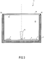
- FIG. 3 shows a lighting device 17, in which now in contrast to the embodiment of FIG. 2 instead of the lens a translucent lens 18 is present without significant visual effect.
- the cover plate 18 also has a transparent, electrically conductive coating 19, which in this example is connected to the housing by an electrically conductive adhesive 20, as a result of which the EMC shield or formation of the receiving space 21 through the housing 2 and the cover plate 18 or the coating 19 takes place.
- the coating 19 may, for example InO: Sn, ZnO: include AI or carbon nanotubes.
- the electrically conductive coating 19 may be applied to the inside or outside of the lens 18 without significant optical effect.
- the present invention is not limited to the present embodiments.
- the shape of the interior may be different, z. B. not square in cross-section, but arbitrarily shaped.
- the housing can also be designed as a heat sink and can be z. B. Identify cooling fins.
- the housing can also consist of metallized or metal-reinforced plastic or another suitable electrically conductive material or composite material.
- no single LED needs to be used as the light source, but it is also possible, for example, to use LED clusters of a plurality of differently colored LEDs whose colors are mixed together in an additive manner.
- the invention is not limited to LEDs, but may include other suitable light sources that require radiating elements to drive them, e.g. B. laser diodes.
- radiant elements can be accommodated, which are not needed to drive the LEDs, but for other purposes.
- the invention is not limited to an automotive application, but may include any suitable lighting application.
Landscapes
- Engineering & Computer Science (AREA)
- General Engineering & Computer Science (AREA)
- Physics & Mathematics (AREA)
- Microelectronics & Electronic Packaging (AREA)
- Optics & Photonics (AREA)
- Power Engineering (AREA)
- Non-Portable Lighting Devices Or Systems Thereof (AREA)
- Arrangement Of Elements, Cooling, Sealing, Or The Like Of Lighting Devices (AREA)
- Led Device Packages (AREA)
Claims (14)
- Dispositif d'éclairage (1) avec un boîtier électriquement conducteur (2) dans l'espace intérieur (3) duquel sont disposés au moins une source de lumière (6), en particulier une LED, et des composants de circuit (7) émettant au moins un rayonnement électromagnétique pour faire fonctionner la ou les sources de lumière (6), et avec un couvercle électriquement conducteur (8 ; 12, 13 ; 18, 19) pour recouvrir les composants de circuit (7), dans lequel le couvercle (8 ; 12, 13 ; 18, 19) et le boîtier (2) sont reliés ensemble électriquement, dans lequel le couvercle (8) comprend un élément optique pour guider la lumière émise par la source de lumière (6) sous la forme d'un réflecteur (8) et dans lequel la source de lumière (6) est guidée à travers une ouverture centrale du réflecteur (8).
- Dispositif d'éclairage (1) selon la revendication 1, dans lequel le rayonnement électromagnétique présente une fréquence d'environ 100 KHz ou plus.
- Dispositif d'éclairage (1) selon l'une quelconque des revendications précédentes dans lequel le réflecteur comporte une métallisation.
- Dispositif d'éclairage (1) selon l'une des revendications 1 à 2, dans lequel le réflecteur (8) est constitué de métal.
- Dispositif d'éclairage (1) selon l'une des revendications précédentes, dans lequel le réflecteur (8) est maintenu sur le boîtier (2) de manière électriquement conductrice.
- Dispositif d'éclairage (1) selon l'une des revendications précédentes, dans lequel le réflecteur (8) est relié au boîtier (2) au moyen d'un adhésif électriquement conducteur.
- Dispositif d'éclairage (1) selon l'une des revendications précédentes, dans lequel le réflecteur est relié au boîtier (2) au moyen d'un élément de liaison mécanique électriquement conducteur.
- Dispositif d'éclairage (1) selon l'une des revendications précédentes, dans lequel le boîtier (2) est constitué de métal.
- Dispositif d'éclairage (1) selon l'une des revendications 1 à 7, dans lequel le boîtier est constitué d'une matière plastique conductrice, en particulier métallisée.
- Dispositif d'éclairage (1) selon l'une des revendications précédentes, dans lequel le boîtier est réalisé sous la forme d'un corps de refroidissement.
- Dispositif d'éclairage (1) selon l'une des revendications précédentes, dans lequel les composants de circuit (7) émettant au moins un rayonnement électromagnétique sont reliés à au moins un élément électronique de filtrage pour réduire le rayonnement électromagnétique des lignes électriques d'amenée.
- Dispositif d'éclairage (1) selon l'une des revendications précédentes, dans lequel la ou les sources de lumière comporte ou comportent au moins une LED (6).
- Dispositif d'éclairage (1) selon la revendication 12, dans lequel les composants de circuit (7) émettant au moins un rayonnement électromagnétique comprennent au moins un composant d'une alimentation à découpage.
- Éclairage de véhicule comportant un dispositif d'éclairage (1) selon l'une des revendications précédentes.
Applications Claiming Priority (2)
| Application Number | Priority Date | Filing Date | Title |
|---|---|---|---|
| DE102007037822A DE102007037822A1 (de) | 2007-08-10 | 2007-08-10 | Beleuchtungsvorrichtung |
| PCT/EP2008/006570 WO2009021694A1 (fr) | 2007-08-10 | 2008-08-08 | Dispositif d'éclairage |
Publications (2)
| Publication Number | Publication Date |
|---|---|
| EP2179217A1 EP2179217A1 (fr) | 2010-04-28 |
| EP2179217B1 true EP2179217B1 (fr) | 2019-03-13 |
Family
ID=39944323
Family Applications (1)
| Application Number | Title | Priority Date | Filing Date |
|---|---|---|---|
| EP08785463.4A Active EP2179217B1 (fr) | 2007-08-10 | 2008-08-08 | Dispositif d'éclairage |
Country Status (6)
| Country | Link |
|---|---|
| US (1) | US8602620B2 (fr) |
| EP (1) | EP2179217B1 (fr) |
| JP (1) | JP5416102B2 (fr) |
| CN (1) | CN101688659B (fr) |
| DE (1) | DE102007037822A1 (fr) |
| WO (1) | WO2009021694A1 (fr) |
Families Citing this family (26)
| Publication number | Priority date | Publication date | Assignee | Title |
|---|---|---|---|---|
| JP5288161B2 (ja) | 2008-02-14 | 2013-09-11 | 東芝ライテック株式会社 | 発光モジュール及び照明装置 |
| DE102009047765A1 (de) * | 2009-12-10 | 2011-06-16 | Ifm Electronic Gmbh | Beleuchtung |
| CN102762920B (zh) * | 2010-02-11 | 2015-04-08 | 帝斯曼知识产权资产管理有限公司 | Led照明装置 |
| DE202010007032U1 (de) * | 2010-04-09 | 2011-08-09 | Tridonic Jennersdorf Gmbh | LED-Modul für Strahler |
| EP2386792B1 (fr) * | 2010-05-12 | 2013-09-11 | Zizala Lichtsysteme GmbH | Module d'éclairage à LED |
| WO2012081258A1 (fr) * | 2010-12-16 | 2012-06-21 | パナソニック株式会社 | Source de lumière d'éclairage et dispositif d'éclairage |
| CN104041204B (zh) * | 2012-02-03 | 2017-09-08 | 飞利浦照明控股有限公司 | 照明驱动器和具有配置用于直接连接至电路接地的内部电磁屏蔽层的壳体 |
| DE102012202354A1 (de) | 2012-02-16 | 2013-08-22 | Osram Gmbh | Leuchtmodul |
| JP5690764B2 (ja) * | 2012-03-06 | 2015-03-25 | 株式会社ホンダアクセス | 照明装置 |
| DE102012204786A1 (de) * | 2012-03-26 | 2013-09-26 | Osram Gmbh | Leuchtvorrichtung mit leuchtstoffkörper auf kühlkörper |
| US20130335980A1 (en) * | 2012-06-13 | 2013-12-19 | Panasonic Corporation | Light emitting device and lighting fixture |
| US9696012B2 (en) * | 2012-10-04 | 2017-07-04 | Guardian Industries Corp. | Embedded LED assembly with optional beam steering optical element, and associated products, and/or methods |
| JP2014149978A (ja) * | 2013-02-01 | 2014-08-21 | Ichikoh Ind Ltd | 車両用灯具 |
| AT513747B1 (de) | 2013-02-28 | 2014-07-15 | Mikroelektronik Ges Mit Beschränkter Haftung Ab | Bestückungsverfahren für Schaltungsträger und Schaltungsträger |
| JP6441652B2 (ja) * | 2014-02-12 | 2018-12-19 | 株式会社小糸製作所 | 車両用灯具 |
| FR3022608B1 (fr) * | 2014-06-19 | 2018-07-20 | Psa Automobiles Sa. | Dispositif d'eclairage et/ou de signalisation generant une lumiere homogene sur un ecran |
| DE102014009594A1 (de) * | 2014-06-27 | 2015-12-31 | Audi Ag | Beleuchtungseinrichtung für ein Kraftfahrzeug mit einer Sicherheitseinrichtung zur Detektion von Fehlzuständen und Verfahren zur Detektion von Fehlerzuständen |
| FR3032516B1 (fr) | 2015-02-06 | 2021-04-16 | Valeo Vision | Dispositif reflecteur d'un module lumineux avec blindage electromagnetique |
| KR101755783B1 (ko) * | 2015-03-05 | 2017-07-20 | 현대자동차주식회사 | 차량 램프용 레이저 광학계 |
| US10100998B2 (en) * | 2015-05-26 | 2018-10-16 | The Boeing Company | Electrically shielded lighting apparatus |
| FR3037730A1 (fr) * | 2015-06-22 | 2016-12-23 | Valeo Vision | Dispositif lumineux de vehicule automobile a rayonnement electromagnetique limite |
| FR3047796B1 (fr) * | 2016-02-15 | 2019-05-24 | Valeo Vision Belgique | Boitier de dispositif lumineux de vehicule automobile |
| DE102017115593A1 (de) * | 2017-07-12 | 2019-01-17 | HELLA GmbH & Co. KGaA | Beleuchtungsvorrichtung für Fahrzeuge |
| FR3090076A1 (fr) * | 2018-12-12 | 2020-06-19 | Valeo Vision Belgique | Dispositif lumineux comportant un circuit électronique protégé par une cage de Faraday |
| WO2022152553A1 (fr) * | 2021-01-12 | 2022-07-21 | Signify Holding B.V. | Agencement d'éclairage pour illumination et éclairage de désinfection |
| FR3138183B1 (fr) * | 2022-07-20 | 2024-07-19 | Valeo Vision | Dispositif lumineux pour véhicule automobile. |
Family Cites Families (28)
| Publication number | Priority date | Publication date | Assignee | Title |
|---|---|---|---|---|
| DE8205219U1 (de) | 1982-02-25 | 1982-05-19 | Walz, Alfred, Prof. Dr.-Ing., 7830 Emmendingen | Arbeitsplatz-leuchte |
| DE3701789A1 (de) | 1987-01-22 | 1988-08-04 | Siemens Ag | Anzeigeeinheit |
| JPH03136938A (ja) * | 1989-10-23 | 1991-06-11 | Nissan Motor Co Ltd | 車両用放電灯ヘッドランプ装置 |
| US5006763A (en) * | 1990-03-12 | 1991-04-09 | General Electric Company | Luminaire for an electrodeless high intensity discharge lamp with electromagnetic interference shielding |
| JP2626155B2 (ja) * | 1990-04-20 | 1997-07-02 | 日産自動車株式会社 | 車両用放電灯ヘッドランプ |
| JP2527264B2 (ja) | 1990-08-28 | 1996-08-21 | 株式会社小糸製作所 | 自動車用ヘッドランプ |
| US5581157A (en) * | 1992-05-20 | 1996-12-03 | Diablo Research Corporation | Discharge lamps and methods for making discharge lamps |
| DE4310307B4 (de) * | 1993-03-30 | 2004-10-14 | Robert Bosch Gmbh | Scheinwerfer für Fahrzeuge |
| WO1996037908A1 (fr) * | 1995-05-24 | 1996-11-28 | Philips Electronics N.V. | Unite d'eclairage et lampe a decharge a faible pression sans electrode, et bulbe de decharge prevu pour etre utilise dans cette unite d'eclairage |
| US5882108A (en) * | 1995-10-12 | 1999-03-16 | Valeo Sylvania L.L.C. | Lighting with EMI shielding |
| JP3195215B2 (ja) * | 1995-12-28 | 2001-08-06 | 株式会社小糸製作所 | 自動車用ヘッドランプ |
| CA2215068C (fr) * | 1996-01-11 | 2004-12-28 | Patent-Treuhand-Gesellschaft Fuer Elektrische Gluehlampen Mbh | Lampe electrique munie d'un culot sans ciment |
| JPH09320540A (ja) | 1996-05-24 | 1997-12-12 | Hitachi Ltd | 無電極蛍光ランプ |
| JP3854421B2 (ja) * | 1999-02-23 | 2006-12-06 | 株式会社小糸製作所 | 放電バルブを有する車両用灯具 |
| CN1334591A (zh) * | 2000-07-18 | 2002-02-06 | 戴培钧 | 一种高频感应无极电子荧光灯 |
| DE10308866A1 (de) * | 2003-02-28 | 2004-09-09 | Osram Opto Semiconductors Gmbh | Beleuchtungsmodul und Verfahren zu dessen Herstellung |
| DE10329078A1 (de) | 2003-06-27 | 2005-01-20 | Osram Opto Semiconductors Gmbh | Beleuchtungsmodul |
| JP3987485B2 (ja) | 2003-12-25 | 2007-10-10 | セイコーエプソン株式会社 | 光源装置及びプロジェクタ |
| DE202004003793U1 (de) | 2004-03-11 | 2004-05-13 | Hella Kg Hueck & Co. | Leuchtdiodenanordnung, insbesondere zum Einbau in Fahrzeuge |
| JP2006184347A (ja) * | 2004-12-27 | 2006-07-13 | Casio Comput Co Ltd | 画像表示装置 |
| JP4656997B2 (ja) * | 2005-04-21 | 2011-03-23 | 株式会社小糸製作所 | 車両用灯具 |
| JP2006302712A (ja) * | 2005-04-21 | 2006-11-02 | Koito Mfg Co Ltd | 車両用前照灯 |
| JP4471169B2 (ja) * | 2005-04-21 | 2010-06-02 | 株式会社小糸製作所 | プロジェクタ型車両用灯具ユニット |
| JP2006302713A (ja) * | 2005-04-21 | 2006-11-02 | Koito Mfg Co Ltd | 車両用前照灯 |
| JP4703375B2 (ja) | 2005-11-08 | 2011-06-15 | 株式会社小糸製作所 | 室内照明灯 |
| DE102006001981A1 (de) | 2006-01-16 | 2007-08-02 | CFL Licht & Design GbR (vertretungsberechtigte Gesellschafter: Wilfried Böhm | Lichtleiste |
| JP4500273B2 (ja) * | 2006-01-31 | 2010-07-14 | 株式会社小糸製作所 | 車両用前照灯 |
| JP4595914B2 (ja) * | 2006-10-03 | 2010-12-08 | パナソニック電工株式会社 | Ledランプ |
-
2007
- 2007-08-10 DE DE102007037822A patent/DE102007037822A1/de not_active Withdrawn
-
2008
- 2008-08-08 WO PCT/EP2008/006570 patent/WO2009021694A1/fr not_active Ceased
- 2008-08-08 JP JP2010512612A patent/JP5416102B2/ja active Active
- 2008-08-08 CN CN2008800209753A patent/CN101688659B/zh active Active
- 2008-08-08 EP EP08785463.4A patent/EP2179217B1/fr active Active
- 2008-08-08 US US12/672,714 patent/US8602620B2/en active Active
Non-Patent Citations (1)
| Title |
|---|
| None * |
Also Published As
| Publication number | Publication date |
|---|---|
| EP2179217A1 (fr) | 2010-04-28 |
| JP2010531037A (ja) | 2010-09-16 |
| DE102007037822A1 (de) | 2009-02-12 |
| CN101688659A (zh) | 2010-03-31 |
| US8602620B2 (en) | 2013-12-10 |
| JP5416102B2 (ja) | 2014-02-12 |
| US20110038172A1 (en) | 2011-02-17 |
| CN101688659B (zh) | 2013-01-23 |
| WO2009021694A1 (fr) | 2009-02-19 |
Similar Documents
| Publication | Publication Date | Title |
|---|---|---|
| EP2179217B1 (fr) | Dispositif d'éclairage | |
| DE202006017924U1 (de) | Beleuchtungseinheit mit einer LED-Lichtquelle | |
| DE102007043903A1 (de) | Leucht-Vorrichtung | |
| DE102009022726A1 (de) | Von der Rückseite anzubringendes Leuchtdioden-Modul für Kombinationsrücklichter an Kraftfahrzeugen | |
| DE102016116116A1 (de) | Lichtvorrichtung, insbesondere eine Signalleuchte für Kraftfahrzeuge | |
| EP3788298B1 (fr) | Module d'éclairage de véhicule à moteur | |
| DE102007033706B4 (de) | Fahrzeugleuchtvorrichtung mit einer dreidimensionalen mehrfarbigen Zwischenlichtscheibe | |
| EP2556287B1 (fr) | Arrangement d'émission de lumière comprenant plusieurs sources de lumière et un élément diffuseur de lumière transparent | |
| DE19916845B4 (de) | Kraftfahrzeugleuchte mit zwei Lichtquellen | |
| DE102010012137A1 (de) | Kraftfahrzeug-Beleuchtungseinrichtung | |
| EP1955895B1 (fr) | Dispositif d'éclairage avec un module DEL | |
| DE102009047765A1 (de) | Beleuchtung | |
| DE102014221815A1 (de) | Leuchtvorrichtung und Scheinwerfer für ein Kraftfahrzeug | |
| DE202012104567U1 (de) | Beleuchtungsanordnung | |
| DE102007056270B4 (de) | Beleuchtungseinheit mit einer LED-Lichtquelle | |
| WO2015040240A1 (fr) | Lampe | |
| WO2019029977A1 (fr) | Lampe comprenant deux sources de lumière et une optique | |
| DE102018211056A1 (de) | Beleuchtungseinheit für ein Kraftfahrzeug | |
| DE102012103309A1 (de) | Lichtleitvorrichtung | |
| EP3244126A1 (fr) | Éclairage comprenant au moins une diode électroluminescente (del), notamment phare comprenant un feu diurne pour un véhicule automobile | |
| EP2216588B1 (fr) | Système modulaire de réflecteur | |
| WO2007028451A1 (fr) | Dispositif d'eclairage destine a un vehicule comportant deux groupes de sources d'eclairage conçus pour au moins deux fonctions d'eclairage | |
| EP3900980A1 (fr) | Feu de véhicule | |
| DE102012007228A1 (de) | Reflektoranordnung für eine Beleuchtungsvorrichtung | |
| DE102012109492A1 (de) | Beleuchtungseinheit für ein Kraftfahrzeug |
Legal Events
| Date | Code | Title | Description |
|---|---|---|---|
| PUAI | Public reference made under article 153(3) epc to a published international application that has entered the european phase |
Free format text: ORIGINAL CODE: 0009012 |
|
| 17P | Request for examination filed |
Effective date: 20100310 |
|
| AK | Designated contracting states |
Kind code of ref document: A1 Designated state(s): AT BE BG CH CY CZ DE DK EE ES FI FR GB GR HR HU IE IS IT LI LT LU LV MC MT NL NO PL PT RO SE SI SK TR |
|
| AX | Request for extension of the european patent |
Extension state: AL BA MK RS |
|
| RIN1 | Information on inventor provided before grant (corrected) |
Inventor name: REINERS, THOMAS Inventor name: VOLLMER, RALF |
|
| DAX | Request for extension of the european patent (deleted) | ||
| RAP1 | Party data changed (applicant data changed or rights of an application transferred) |
Owner name: OSRAM AG |
|
| 17Q | First examination report despatched |
Effective date: 20121130 |
|
| RAP1 | Party data changed (applicant data changed or rights of an application transferred) |
Owner name: OSRAM GMBH |
|
| RAP1 | Party data changed (applicant data changed or rights of an application transferred) |
Owner name: OSRAM GMBH |
|
| REG | Reference to a national code |
Ref country code: DE Ref legal event code: R079 Ref document number: 502008016647 Country of ref document: DE Free format text: PREVIOUS MAIN CLASS: F21V0025000000 Ipc: F21V0023000000 |
|
| GRAP | Despatch of communication of intention to grant a patent |
Free format text: ORIGINAL CODE: EPIDOSNIGR1 |
|
| STAA | Information on the status of an ep patent application or granted ep patent |
Free format text: STATUS: GRANT OF PATENT IS INTENDED |
|
| RIC1 | Information provided on ipc code assigned before grant |
Ipc: F21V 25/00 20060101ALI20180514BHEP Ipc: F21S 41/00 20180101ALI20180514BHEP Ipc: F21V 23/00 20060101AFI20180514BHEP Ipc: F21V 3/04 20060101ALI20180514BHEP |
|
| INTG | Intention to grant announced |
Effective date: 20180606 |
|
| RIN1 | Information on inventor provided before grant (corrected) |
Inventor name: REINERS, THOMAS Inventor name: VOLLMER, RALPH |
|
| GRAJ | Information related to disapproval of communication of intention to grant by the applicant or resumption of examination proceedings by the epo deleted |
Free format text: ORIGINAL CODE: EPIDOSDIGR1 |
|
| STAA | Information on the status of an ep patent application or granted ep patent |
Free format text: STATUS: EXAMINATION IS IN PROGRESS |
|
| GRAS | Grant fee paid |
Free format text: ORIGINAL CODE: EPIDOSNIGR3 |
|
| STAA | Information on the status of an ep patent application or granted ep patent |
Free format text: STATUS: GRANT OF PATENT IS INTENDED |
|
| GRAP | Despatch of communication of intention to grant a patent |
Free format text: ORIGINAL CODE: EPIDOSNIGR1 |
|
| INTC | Intention to grant announced (deleted) | ||
| INTG | Intention to grant announced |
Effective date: 20181102 |
|
| GRAA | (expected) grant |
Free format text: ORIGINAL CODE: 0009210 |
|
| STAA | Information on the status of an ep patent application or granted ep patent |
Free format text: STATUS: THE PATENT HAS BEEN GRANTED |
|
| RIC1 | Information provided on ipc code assigned before grant |
Ipc: F21V 23/00 20150101AFI20180514BHEP Ipc: F21S 41/00 20180101ALI20180514BHEP Ipc: F21V 25/00 20060101ALI20180514BHEP Ipc: F21V 3/04 20180101ALI20180514BHEP |
|
| AK | Designated contracting states |
Kind code of ref document: B1 Designated state(s): AT BE BG CH CY CZ DE DK EE ES FI FR GB GR HR HU IE IS IT LI LT LU LV MC MT NL NO PL PT RO SE SI SK TR |
|
| REG | Reference to a national code |
Ref country code: GB Ref legal event code: FG4D Free format text: NOT ENGLISH |
|
| REG | Reference to a national code |
Ref country code: CH Ref legal event code: EP Ref country code: AT Ref legal event code: REF Ref document number: 1108205 Country of ref document: AT Kind code of ref document: T Effective date: 20190315 |
|
| REG | Reference to a national code |
Ref country code: IE Ref legal event code: FG4D Free format text: LANGUAGE OF EP DOCUMENT: GERMAN |
|
| REG | Reference to a national code |
Ref country code: DE Ref legal event code: R096 Ref document number: 502008016647 Country of ref document: DE |
|
| REG | Reference to a national code |
Ref country code: NL Ref legal event code: MP Effective date: 20190313 |
|
| REG | Reference to a national code |
Ref country code: LT Ref legal event code: MG4D |
|
| PG25 | Lapsed in a contracting state [announced via postgrant information from national office to epo] |
Ref country code: NO Free format text: LAPSE BECAUSE OF FAILURE TO SUBMIT A TRANSLATION OF THE DESCRIPTION OR TO PAY THE FEE WITHIN THE PRESCRIBED TIME-LIMIT Effective date: 20190613 Ref country code: FI Free format text: LAPSE BECAUSE OF FAILURE TO SUBMIT A TRANSLATION OF THE DESCRIPTION OR TO PAY THE FEE WITHIN THE PRESCRIBED TIME-LIMIT Effective date: 20190313 Ref country code: SE Free format text: LAPSE BECAUSE OF FAILURE TO SUBMIT A TRANSLATION OF THE DESCRIPTION OR TO PAY THE FEE WITHIN THE PRESCRIBED TIME-LIMIT Effective date: 20190313 Ref country code: LT Free format text: LAPSE BECAUSE OF FAILURE TO SUBMIT A TRANSLATION OF THE DESCRIPTION OR TO PAY THE FEE WITHIN THE PRESCRIBED TIME-LIMIT Effective date: 20190313 |
|
| PG25 | Lapsed in a contracting state [announced via postgrant information from national office to epo] |
Ref country code: GR Free format text: LAPSE BECAUSE OF FAILURE TO SUBMIT A TRANSLATION OF THE DESCRIPTION OR TO PAY THE FEE WITHIN THE PRESCRIBED TIME-LIMIT Effective date: 20190614 Ref country code: HR Free format text: LAPSE BECAUSE OF FAILURE TO SUBMIT A TRANSLATION OF THE DESCRIPTION OR TO PAY THE FEE WITHIN THE PRESCRIBED TIME-LIMIT Effective date: 20190313 Ref country code: NL Free format text: LAPSE BECAUSE OF FAILURE TO SUBMIT A TRANSLATION OF THE DESCRIPTION OR TO PAY THE FEE WITHIN THE PRESCRIBED TIME-LIMIT Effective date: 20190313 Ref country code: BG Free format text: LAPSE BECAUSE OF FAILURE TO SUBMIT A TRANSLATION OF THE DESCRIPTION OR TO PAY THE FEE WITHIN THE PRESCRIBED TIME-LIMIT Effective date: 20190613 Ref country code: LV Free format text: LAPSE BECAUSE OF FAILURE TO SUBMIT A TRANSLATION OF THE DESCRIPTION OR TO PAY THE FEE WITHIN THE PRESCRIBED TIME-LIMIT Effective date: 20190313 |
|
| PG25 | Lapsed in a contracting state [announced via postgrant information from national office to epo] |
Ref country code: SK Free format text: LAPSE BECAUSE OF FAILURE TO SUBMIT A TRANSLATION OF THE DESCRIPTION OR TO PAY THE FEE WITHIN THE PRESCRIBED TIME-LIMIT Effective date: 20190313 Ref country code: RO Free format text: LAPSE BECAUSE OF FAILURE TO SUBMIT A TRANSLATION OF THE DESCRIPTION OR TO PAY THE FEE WITHIN THE PRESCRIBED TIME-LIMIT Effective date: 20190313 Ref country code: EE Free format text: LAPSE BECAUSE OF FAILURE TO SUBMIT A TRANSLATION OF THE DESCRIPTION OR TO PAY THE FEE WITHIN THE PRESCRIBED TIME-LIMIT Effective date: 20190313 Ref country code: IT Free format text: LAPSE BECAUSE OF FAILURE TO SUBMIT A TRANSLATION OF THE DESCRIPTION OR TO PAY THE FEE WITHIN THE PRESCRIBED TIME-LIMIT Effective date: 20190313 Ref country code: ES Free format text: LAPSE BECAUSE OF FAILURE TO SUBMIT A TRANSLATION OF THE DESCRIPTION OR TO PAY THE FEE WITHIN THE PRESCRIBED TIME-LIMIT Effective date: 20190313 Ref country code: PT Free format text: LAPSE BECAUSE OF FAILURE TO SUBMIT A TRANSLATION OF THE DESCRIPTION OR TO PAY THE FEE WITHIN THE PRESCRIBED TIME-LIMIT Effective date: 20190713 Ref country code: CZ Free format text: LAPSE BECAUSE OF FAILURE TO SUBMIT A TRANSLATION OF THE DESCRIPTION OR TO PAY THE FEE WITHIN THE PRESCRIBED TIME-LIMIT Effective date: 20190313 |
|
| PG25 | Lapsed in a contracting state [announced via postgrant information from national office to epo] |
Ref country code: PL Free format text: LAPSE BECAUSE OF FAILURE TO SUBMIT A TRANSLATION OF THE DESCRIPTION OR TO PAY THE FEE WITHIN THE PRESCRIBED TIME-LIMIT Effective date: 20190313 |
|
| REG | Reference to a national code |
Ref country code: DE Ref legal event code: R097 Ref document number: 502008016647 Country of ref document: DE |
|
| PG25 | Lapsed in a contracting state [announced via postgrant information from national office to epo] |
Ref country code: IS Free format text: LAPSE BECAUSE OF FAILURE TO SUBMIT A TRANSLATION OF THE DESCRIPTION OR TO PAY THE FEE WITHIN THE PRESCRIBED TIME-LIMIT Effective date: 20190713 |
|
| PLBE | No opposition filed within time limit |
Free format text: ORIGINAL CODE: 0009261 |
|
| STAA | Information on the status of an ep patent application or granted ep patent |
Free format text: STATUS: NO OPPOSITION FILED WITHIN TIME LIMIT |
|
| PG25 | Lapsed in a contracting state [announced via postgrant information from national office to epo] |
Ref country code: DK Free format text: LAPSE BECAUSE OF FAILURE TO SUBMIT A TRANSLATION OF THE DESCRIPTION OR TO PAY THE FEE WITHIN THE PRESCRIBED TIME-LIMIT Effective date: 20190313 |
|
| 26N | No opposition filed |
Effective date: 20191216 |
|
| PG25 | Lapsed in a contracting state [announced via postgrant information from national office to epo] |
Ref country code: SI Free format text: LAPSE BECAUSE OF FAILURE TO SUBMIT A TRANSLATION OF THE DESCRIPTION OR TO PAY THE FEE WITHIN THE PRESCRIBED TIME-LIMIT Effective date: 20190313 |
|
| PG25 | Lapsed in a contracting state [announced via postgrant information from national office to epo] |
Ref country code: TR Free format text: LAPSE BECAUSE OF FAILURE TO SUBMIT A TRANSLATION OF THE DESCRIPTION OR TO PAY THE FEE WITHIN THE PRESCRIBED TIME-LIMIT Effective date: 20190313 |
|
| GBPC | Gb: european patent ceased through non-payment of renewal fee |
Effective date: 20190808 |
|
| PG25 | Lapsed in a contracting state [announced via postgrant information from national office to epo] |
Ref country code: LU Free format text: LAPSE BECAUSE OF NON-PAYMENT OF DUE FEES Effective date: 20190808 Ref country code: MC Free format text: LAPSE BECAUSE OF FAILURE TO SUBMIT A TRANSLATION OF THE DESCRIPTION OR TO PAY THE FEE WITHIN THE PRESCRIBED TIME-LIMIT Effective date: 20190313 Ref country code: LI Free format text: LAPSE BECAUSE OF NON-PAYMENT OF DUE FEES Effective date: 20190831 Ref country code: CH Free format text: LAPSE BECAUSE OF NON-PAYMENT OF DUE FEES Effective date: 20190831 |
|
| REG | Reference to a national code |
Ref country code: BE Ref legal event code: MM Effective date: 20190831 |
|
| PG25 | Lapsed in a contracting state [announced via postgrant information from national office to epo] |
Ref country code: FR Free format text: LAPSE BECAUSE OF NON-PAYMENT OF DUE FEES Effective date: 20190831 Ref country code: IE Free format text: LAPSE BECAUSE OF NON-PAYMENT OF DUE FEES Effective date: 20190808 |
|
| PG25 | Lapsed in a contracting state [announced via postgrant information from national office to epo] |
Ref country code: GB Free format text: LAPSE BECAUSE OF NON-PAYMENT OF DUE FEES Effective date: 20190808 Ref country code: BE Free format text: LAPSE BECAUSE OF NON-PAYMENT OF DUE FEES Effective date: 20190831 |
|
| REG | Reference to a national code |
Ref country code: AT Ref legal event code: MM01 Ref document number: 1108205 Country of ref document: AT Kind code of ref document: T Effective date: 20190808 |
|
| PG25 | Lapsed in a contracting state [announced via postgrant information from national office to epo] |
Ref country code: AT Free format text: LAPSE BECAUSE OF NON-PAYMENT OF DUE FEES Effective date: 20190808 |
|
| PG25 | Lapsed in a contracting state [announced via postgrant information from national office to epo] |
Ref country code: CY Free format text: LAPSE BECAUSE OF FAILURE TO SUBMIT A TRANSLATION OF THE DESCRIPTION OR TO PAY THE FEE WITHIN THE PRESCRIBED TIME-LIMIT Effective date: 20190313 |
|
| PG25 | Lapsed in a contracting state [announced via postgrant information from national office to epo] |
Ref country code: MT Free format text: LAPSE BECAUSE OF FAILURE TO SUBMIT A TRANSLATION OF THE DESCRIPTION OR TO PAY THE FEE WITHIN THE PRESCRIBED TIME-LIMIT Effective date: 20190313 Ref country code: HU Free format text: LAPSE BECAUSE OF FAILURE TO SUBMIT A TRANSLATION OF THE DESCRIPTION OR TO PAY THE FEE WITHIN THE PRESCRIBED TIME-LIMIT; INVALID AB INITIO Effective date: 20080808 |
|
| P01 | Opt-out of the competence of the unified patent court (upc) registered |
Effective date: 20230821 |
|
| PGFP | Annual fee paid to national office [announced via postgrant information from national office to epo] |
Ref country code: DE Payment date: 20250820 Year of fee payment: 18 |