EP2180127A2 - Schwelle für Gebäudeöffnungen - Google Patents
Schwelle für Gebäudeöffnungen Download PDFInfo
- Publication number
- EP2180127A2 EP2180127A2 EP20090173988 EP09173988A EP2180127A2 EP 2180127 A2 EP2180127 A2 EP 2180127A2 EP 20090173988 EP20090173988 EP 20090173988 EP 09173988 A EP09173988 A EP 09173988A EP 2180127 A2 EP2180127 A2 EP 2180127A2
- Authority
- EP
- European Patent Office
- Prior art keywords
- support piece
- building
- wall
- fiber
- floor
- Prior art date
- Legal status (The legal status is an assumption and is not a legal conclusion. Google has not performed a legal analysis and makes no representation as to the accuracy of the status listed.)
- Withdrawn
Links
- 239000004567 concrete Substances 0.000 claims abstract description 35
- 239000000835 fiber Substances 0.000 claims abstract description 28
- 239000011810 insulating material Substances 0.000 claims abstract description 18
- 230000002093 peripheral effect Effects 0.000 claims abstract description 10
- 239000004568 cement Substances 0.000 claims abstract description 8
- 239000000203 mixture Substances 0.000 claims abstract description 5
- 239000002270 dispersing agent Substances 0.000 claims abstract description 4
- 239000011159 matrix material Substances 0.000 claims abstract description 3
- 239000011210 fiber-reinforced concrete Substances 0.000 claims description 15
- 230000002787 reinforcement Effects 0.000 claims description 12
- XLYOFNOQVPJJNP-UHFFFAOYSA-N water Substances O XLYOFNOQVPJJNP-UHFFFAOYSA-N 0.000 claims description 9
- 238000004519 manufacturing process Methods 0.000 claims description 5
- 239000000853 adhesive Substances 0.000 claims description 3
- 230000001070 adhesive effect Effects 0.000 claims description 3
- 102000010970 Connexin Human genes 0.000 claims description 2
- 108050001175 Connexin Proteins 0.000 claims description 2
- 230000001186 cumulative effect Effects 0.000 claims description 2
- 210000003976 gap junction Anatomy 0.000 claims description 2
- 239000002245 particle Substances 0.000 claims description 2
- 238000000034 method Methods 0.000 abstract description 8
- 239000000945 filler Substances 0.000 abstract 1
- 238000009413 insulation Methods 0.000 description 13
- 235000005921 Cynara humilis Nutrition 0.000 description 6
- 240000002228 Cynara humilis Species 0.000 description 6
- 239000003292 glue Substances 0.000 description 5
- 239000000463 material Substances 0.000 description 5
- 238000010276 construction Methods 0.000 description 4
- 238000004026 adhesive bonding Methods 0.000 description 2
- 238000005266 casting Methods 0.000 description 2
- 239000012212 insulator Substances 0.000 description 2
- 238000000465 moulding Methods 0.000 description 2
- 241001080024 Telles Species 0.000 description 1
- 238000009435 building construction Methods 0.000 description 1
- 239000003795 chemical substances by application Substances 0.000 description 1
- 238000005553 drilling Methods 0.000 description 1
- 239000011521 glass Substances 0.000 description 1
- 238000002347 injection Methods 0.000 description 1
- 239000007924 injection Substances 0.000 description 1
- 230000035515 penetration Effects 0.000 description 1
- 230000001737 promoting effect Effects 0.000 description 1
- 238000009877 rendering Methods 0.000 description 1
Images




Classifications
-
- E—FIXED CONSTRUCTIONS
- E06—DOORS, WINDOWS, SHUTTERS, OR ROLLER BLINDS IN GENERAL; LADDERS
- E06B—FIXED OR MOVABLE CLOSURES FOR OPENINGS IN BUILDINGS, VEHICLES, FENCES OR LIKE ENCLOSURES IN GENERAL, e.g. DOORS, WINDOWS, BLINDS, GATES
- E06B1/00—Border constructions of openings in walls, floors, or ceilings; Frames to be rigidly mounted in such openings
- E06B1/70—Sills; Thresholds
- E06B1/702—Window sills
-
- E—FIXED CONSTRUCTIONS
- E06—DOORS, WINDOWS, SHUTTERS, OR ROLLER BLINDS IN GENERAL; LADDERS
- E06B—FIXED OR MOVABLE CLOSURES FOR OPENINGS IN BUILDINGS, VEHICLES, FENCES OR LIKE ENCLOSURES IN GENERAL, e.g. DOORS, WINDOWS, BLINDS, GATES
- E06B1/00—Border constructions of openings in walls, floors, or ceilings; Frames to be rigidly mounted in such openings
- E06B1/70—Sills; Thresholds
-
- E—FIXED CONSTRUCTIONS
- E06—DOORS, WINDOWS, SHUTTERS, OR ROLLER BLINDS IN GENERAL; LADDERS
- E06B—FIXED OR MOVABLE CLOSURES FOR OPENINGS IN BUILDINGS, VEHICLES, FENCES OR LIKE ENCLOSURES IN GENERAL, e.g. DOORS, WINDOWS, BLINDS, GATES
- E06B7/00—Special arrangements or measures in connection with doors or windows
- E06B7/14—Measures for draining-off condensed water or water leaking-in frame members for draining off condensation water, throats at the bottom of a sash
Definitions
- the present invention relates to the thresholds and more particularly the support pieces for building opening supports such as door and window supports.
- building floors have usually been made by pouring horizontal concrete slabs.
- the same concrete slab constitutes in one piece the balcony and the interior floor of the building.
- the carpentry is based on a support piece attached to the slab, which borders the underside of the door, and which forms an elevation opposing the penetration of rainwater and runoff.
- the support piece is generally a prefabricated or cast-in-place concrete beam, possibly covered with an appearance layer, which thus has good mechanical strength to support the joinery and the steps of the users, and an aesthetic appearance of finish correct.
- a disadvantage of such a support piece is that it is heavy, which makes it difficult handling during the construction of a building. Another disadvantage is the risk of cracks appearing in its massive structure. Another disadvantage is its high thermal conductivity, which further promotes thermal conduction between the interior and exterior of a building.
- thermal insulation between an inner concrete slab forming the interior floor of the building and an outer concrete slab forming the balcony, other means being provided to support the outer concrete slab.
- the thermal insulation may be in correspondence of an insulating layer of upper and lower vertical walls adjacent to the slabs, providing continuity of insulation. But, right doors, we must still provide a support part supporting the joinery, and this support piece is necessarily in contact with the inner and outer slabs.
- a massive support piece creates a thermal bridge between the two slabs, rendering illusory the respect of future construction standards.
- Document is known CH 648 079 A5 a support member for opening buildings according to the preamble of claim 1, with a rigid shell made of fiber concrete whose peripheral wall forms upper and lateral walls of the support piece, and which defines a inner cavity filled with a thermally insulating material.
- the rigid shell made of fiber concrete is completely closed, the fiber concrete forming not only the top wall and the side walls, but also a closed bottom wall.
- the insulating material is introduced into the closed interior compartment of the shell by a lateral injection opening.
- the problem proposed by the present invention is to design a support piece for building opening supports which both has good mechanical strength, a good finish appearance, and good thermal insulation capacity.
- the invention proposes to design a building comprising an opening support provided with a support piece according to the invention.
- the invention proposes a method for manufacturing a support piece according to the invention.
- the invention proposes an improvement that makes it possible to reduce the height differences of a threshold, to respect the access standards for the disabled, while guaranteeing watertightness and thermal insulation.
- the fiber-reinforced concrete of the rigid shell has the advantage of having a suitable mechanical strength to make the support pieces, although having a reduced thickness.
- fiber-reinforced concrete offers the advantage of having a mechanical strength that is ten times greater than that of conventional concrete for the same thickness.
- the use of fiber concrete to make the rigid shell allows in particular to obtain a shell, so a reduced thickness element, but which is rigid enough to support the weight of people walking on the threshold. Thus, less material is required to make opening supports according to the invention.
- the rigid shell thus produced offers the advantage of having a low weight. It is thus more easily manipulated.
- the small thickness of material required to make the rigid shell reduces the risk of cracks in the rigid shell.
- the rigid shell has a low thermal conductivity.
- the specific structure of the support piece according to the invention makes it possible to effectively reduce the thermal bridge when the support piece is positioned in the junction zone between the concrete slab forming the floor located inside a building. and the concrete slab building the balcony located outside the building.
- the gap between the concrete slabs being previously filled with a thermal insulator, and the rigid shell being open towards its lower face, only the upper wall of rigid fiber-reinforced concrete shell is likely to still constitute a residual thermal bridge. Its small section, and its distance vis-à-vis the slabs, thus ensure an effective rupture of the thermal bridge.
- the lower face of the support piece, in contact with the inner and outer slabs, is made of insulating material, providing good thermal insulation between the two slabs.
- Such a support piece design with a rigid shell filled with an insulating material and open on its underside offers the possibility of prefabricating very easily the support piece, the rigid shell can be made by casting fiber concrete around the a core of thermally insulating material. On a construction site, all that remains is to fix the support piece by fixing techniques that are simple to implement, quick and inexpensive.
- the insulating material is incompressible.
- the thermal insulation then strengthens the good mechanical strength of the support piece by participating in it.
- the peripheral wall of the rigid shell has a thickness of about 2 cm.
- This type of concrete has excellent mechanical strength.
- the product distributed by Lafarge under the trademark Ductal ® may be used.
- the inner cavity comprises intermediate fiber reinforced reinforcements supporting the upper wall.
- a support piece comprising fiber reinforced reinforcements has improved mechanical properties.
- a building comprises at least one opening support formed of a support piece according to the first aspect of the invention adapted to be fixed on the building structure .
- the opening support thus contributes to the thermal insulation of the building, in order to respect the future standards of housing construction.
- the wall in which the opening for the window is formed is suitable.
- the support piece is glued on the ground or on the upper edge of the wall by a flexible outer glue such as a tile adhesive.
- Glue is an easy assembly method to implement and inexpensive. The use of a conventional exterior glue makes this assembly even easier.
- the support piece is fixed on the ground or on the upper edge of the wall by brackets.
- This method of fixing the support piece allows a stronger attachment than the glue.
- Molding is a process that is easy to implement and makes it possible to produce opening supports in mass production.
- the support piece for building opening supports is shaped not only to guarantee watertightness and thermal insulation, as in the previously defined embodiment, but also to reduce the height differences of a threshold, allowing to respect the standards of access for handicapped people.
- the support piece further comprises an outer extension in the form of transverse drainage channel, which can be embedded in a housing provided in the outer slab of balcony or terrace, and which is covered with 'a grid.
- the grid can be located level with the upper face of the outer slab, and the upper surface of the support piece top can be lowered while maintaining a sufficient drop of water flow relative to the bottom of the the channel, the elevation of bearing surface being reduced between the top of the support piece and the level of the grid.
- the figure 1 illustrates a rigid shell 7a of a support piece 100 ( Figures 2 to 5 ) according to one embodiment of the invention.
- the rigid shell 7a has a peripheral wall 200 forming an upper wall 9, a lower face 10 in recess, and two side walls 11 and 12, defining an inner cavity 16.
- the rigid shell 7a is fully open on its underside 10.
- side wall 11 comprises an inner face 110a and an outer face 110b.
- the side wall 12 comprises an inner face 120a and an outer face 120b.
- the upper wall 9 comprises an inner face 90a and an outer face 90b. It comprises a flat wall portion 9a designed to receive the carpentry portion 8 of a bay window ( figures 4 and 5 ), a sloping portion 9b to ensure watertightness by allowing and promoting the flow of water coming down from the bay window to the outside of a building, and a connecting projection 9c which raises the flat wall portion 9a with respect to the sloped wall portion 9b, so as to create a sufficient height difference between the level of an outer slab and the level of the flat wall portion 9a.
- a notch 15 is provided in the side wall 12 to allow the embedding of a tile-like floor covering 4 ( figure 4 ).
- the thickness ⁇ of the peripheral wall 200 of the rigid shell 7a is substantially constant for the flat wall portion 9a, the sloping wall portion 9b, and the side wall 11. This thickness e may for example be about 2 cm.
- the presence of the notch 15 in the side wall 12 induces that the thickness ⁇ 'of the side wall 12 is slightly greater than the thickness ⁇ of the flat wall portions 9a, sloping 9b and the side wall 11, to ensure the good mechanical strength of the support piece 100 ( Figures 2 to 5 ).
- the side wall 12 may also have the same thickness ⁇ substantially constant.
- the thickness of the peripheral wall 200 of the rigid shell 7a is substantially constant for the flat wall portion 9a, the sloping wall portion 9b, and the side walls 11 and 12.
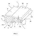
- the figures 2 and 3 illustrate a support piece 100 which comprises a rigid shell 7a whose internal cavity 16 ( figure 1 ) is filled with a material thermally insulating 7b.
- the same essential means of the rigid shell 7a are identified by the same reference numerals as on the figure 1 .
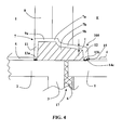
- the figures 4 and 5 illustrate two modes of assembly of the support piece 100 on structural parts 1 and 2 of a building. These parts 1 and 2 may be concrete slabs on either side of a door sill.
- the figure 4 illustrates an opening support 7 for a door formed by a support piece 100 similar to that shown on the figures 2 and 3 .
- the support piece 100 is fixed in a first assembly mode, namely the glue 13a and 13b.
- the same essential means of the support piece 100 are identified by the same reference numerals as on the figures 2 and 3 .
- the support piece 100 supports the carpentry part 8 of a bay or glass door.
- the support piece 100 To play its role of thermal insulation, the support piece 100 must be positioned in the junction zone between a concrete slab 2 forming the floor located inside a building I and the concrete slab 1 carrying out the balcony located outside E of the building.
- the gap 17 between the concrete slabs 1 and 2 is filled beforehand with a thermal insulator 6.
- the support piece 100 illustrated on this figure 4 is as illustrated on the figure 1 .
- the side wall 12 has a notch 15.
- the support piece 100 for door is fixed by gluing (13a and 13b) on the concrete slabs 1 and 2.
- gluing 13a and 13b
- This fastening can be effected by gluing or any other fastening means.
- the outer floor covering 4 passes under the notch 15 and conceals the angle 14c.
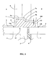
- the figure 5 illustrates the support piece 100 of figures 2 and 3 which is fixed according to a second method of assembly for producing a door support.
- the same essential means are identified by the same numerical references as on the figure 4 .
- the support piece 100 is fixed in the junction zone between the inner slab 2 and the outer slab 1 by brackets 14a and 14b.
- the inner floor covering 5 conceals the angle 14a.
- the outer floor covering 4 conceals the angle 14b.
- the figure 6 illustrates the method of manufacturing a support piece 100 according to one embodiment of the invention.
- a mold 18 has the female shape of the external shape that is to be given to the rigid shell 7a.
- a core of insulating material 7b has the male shape of the inner shape that is to be given to the rigid shell 7a.
- the core of insulating material 7b is positioned in the mold 18 leaving a space 19 between it and the mold 18. Fiber concrete 70 is poured into the space 19 to produce the rigid shell 7a of the support piece 100.
- the fiber-reinforced concrete 70 gradually fills the space 19.
- the fiber-reinforced concrete 70 is allowed to settle and the mold 18 is removed.
- the support piece 100 is thus obtained as illustrated in FIGS. figures 2 and 3 .
- Opening support 100 of Figures 7 to 9 includes the same essential means as the Figures 1 to 5 . These same essential means are identified by the same reference numbers.
- the opening support 100 further comprises fiber reinforced concrete intermediate reinforcements, a drop of water 21, and a fiber-reinforced concrete bottom wall 22 occupying a portion of the lower face 10 of the opening support 100.
- the reinforcements 20 advantageously connect the upper wall 9 to the lower wall 22, to promote rigidity.
- the figure 8 illustrates that the reinforcements 20 are located.
- the number of reinforcements can be adapted according to the support piece.
- the support piece 100 When the opening is a window, the support piece 100 is positioned on the building structure portion formed by the upper edge 3a of the wall 3 ( figure 9 ), and it protrudes cantilevered outward. It is therefore advantageous for the support piece 100 to be reinforced mechanically. This role of mechanical reinforcement is filled by the reinforcements 20 and the bottom wall 22 of fiber concrete. The position of the reinforcements 20 and the dimension of the bottom wall 22 are chosen so that the support piece 100 rests on the upper edge 3a of the wall 3 by the base of its side wall 11 (inside the building) and by a portion at least of its bottom wall 22, as illustrated on the figure 9 .
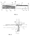
- FIG. 10 to 12 illustrate another embodiment of a support piece 100 according to the invention.
- connection projection such as the projection 9c of the previous embodiment, between the flat wall portion 9a and the sloped wall portion 9b.
- the fiber-reinforced concrete shell 7a further comprises an outer extension 30 in the form of an upwardly open transverse channel bounded by a flat bottom wall 31, the intermediate lateral wall 12, and a front lateral wall 32.
- the upper face 33 The open channel of the transverse channel is substantially at the lower end of the sloping wall portion 9b.
- a grid 34 schematically illustrated, closes the open upper face. On the figure 10 only a limited section of the grid 34 has been shown, but it will be understood that the grid 34 covers the whole of the open upper face 33 of the transverse channel.
- the gate 34 is engaged in two shoulders 35 and 36 made respectively at the upper ends of the side walls 12 and 32.
- the flat wall portion 9a constitutes the top of the support piece 100, and it is connected by the sloped wall portion 9b to the grid 34.
- the height difference H between the flat wall portion 9a and the grid 34 is about 2 cm.
- the depth of the transverse channel that is to say the distance between the bottom wall 31 and the top of the grid 34, is about 5 cm. This results in a total elevation of about 7 cm between the bottom 31 of the transverse channel and the level of the flat wall portion 9a.
- the height differences between the outer slab and the inner slab are very substantially reduced to the passage of the support piece 100, so that the support piece 100 illustrated in this embodiment of the figure 11 is particularly well suited for the passage of the disabled.
- the watertightness of the transversal channel is ensured by the fact that the fiber concrete is itself impermeable, unlike ordinary concrete.
Landscapes
- Engineering & Computer Science (AREA)
- Civil Engineering (AREA)
- Structural Engineering (AREA)
- Building Environments (AREA)
- Reinforcement Elements For Buildings (AREA)
- Door And Window Frames Mounted To Openings (AREA)
Applications Claiming Priority (1)
| Application Number | Priority Date | Filing Date | Title |
|---|---|---|---|
| FR0857262A FR2937675B1 (fr) | 2008-10-25 | 2008-10-25 | Piece d'appui pour appuis d'ouverture de batiments |
Publications (2)
| Publication Number | Publication Date |
|---|---|
| EP2180127A2 true EP2180127A2 (de) | 2010-04-28 |
| EP2180127A3 EP2180127A3 (de) | 2011-01-05 |
Family
ID=40673174
Family Applications (1)
| Application Number | Title | Priority Date | Filing Date |
|---|---|---|---|
| EP20090173988 Withdrawn EP2180127A3 (de) | 2008-10-25 | 2009-10-23 | Schwelle für Gebäudeöffnungen |
Country Status (2)
| Country | Link |
|---|---|
| EP (1) | EP2180127A3 (de) |
| FR (1) | FR2937675B1 (de) |
Cited By (4)
| Publication number | Priority date | Publication date | Assignee | Title |
|---|---|---|---|---|
| GB2482727A (en) * | 2010-08-13 | 2012-02-15 | Khim Meng Teo | Insulated cavity tray for a door cill |
| GB2511802A (en) * | 2013-03-14 | 2014-09-17 | Jeremy Patrick Leighton | Insulated architectural profiles |
| FR3003595A1 (fr) * | 2013-03-25 | 2014-09-26 | Weser | Seuil de porte prefabrique a acces facilite |
| FR3081181A1 (fr) * | 2018-05-16 | 2019-11-22 | Mineraltech | Appui d'ouverture et encadrement d'ouverture pour batiment |
Families Citing this family (1)
| Publication number | Priority date | Publication date | Assignee | Title |
|---|---|---|---|---|
| FR2986552B1 (fr) * | 2012-02-07 | 2015-04-10 | Wienerberger | Appui de fenetre isole en zone arriere |
Citations (2)
| Publication number | Priority date | Publication date | Assignee | Title |
|---|---|---|---|---|
| DD118912A1 (de) * | 1975-04-07 | 1976-03-20 | ||
| CH648079A5 (en) | 1980-03-14 | 1985-02-28 | Zuercher Ziegeleien | Insulating structural element and frame of a masonry-wall opening with the structural element |
Family Cites Families (3)
| Publication number | Priority date | Publication date | Assignee | Title |
|---|---|---|---|---|
| SE510046C2 (sv) * | 1994-03-25 | 1999-04-12 | Haakan Lindgren | Gjutformelement för utformning av urtag och öppningar, samt förfarande för utformning av urtag och öppningar |
| DE4415550A1 (de) * | 1994-05-03 | 1995-11-09 | Hm Betonfertigteilwerk Hans Ma | Betonfertigteil, sowie Vorrichtung und Verfahren zu seiner Herstellung |
| GB2381287B (en) * | 2001-10-25 | 2005-05-25 | Wintem Limted | A threshold unit for an exterior door of a building |
-
2008
- 2008-10-25 FR FR0857262A patent/FR2937675B1/fr active Active
-
2009
- 2009-10-23 EP EP20090173988 patent/EP2180127A3/de not_active Withdrawn
Patent Citations (2)
| Publication number | Priority date | Publication date | Assignee | Title |
|---|---|---|---|---|
| DD118912A1 (de) * | 1975-04-07 | 1976-03-20 | ||
| CH648079A5 (en) | 1980-03-14 | 1985-02-28 | Zuercher Ziegeleien | Insulating structural element and frame of a masonry-wall opening with the structural element |
Cited By (5)
| Publication number | Priority date | Publication date | Assignee | Title |
|---|---|---|---|---|
| GB2482727A (en) * | 2010-08-13 | 2012-02-15 | Khim Meng Teo | Insulated cavity tray for a door cill |
| GB2482727B (en) * | 2010-08-13 | 2016-06-15 | Meng Teo Khim | Insulated cavity tray |
| GB2511802A (en) * | 2013-03-14 | 2014-09-17 | Jeremy Patrick Leighton | Insulated architectural profiles |
| FR3003595A1 (fr) * | 2013-03-25 | 2014-09-26 | Weser | Seuil de porte prefabrique a acces facilite |
| FR3081181A1 (fr) * | 2018-05-16 | 2019-11-22 | Mineraltech | Appui d'ouverture et encadrement d'ouverture pour batiment |
Also Published As
| Publication number | Publication date |
|---|---|
| EP2180127A3 (de) | 2011-01-05 |
| FR2937675A1 (fr) | 2010-04-30 |
| FR2937675B1 (fr) | 2013-06-07 |
Similar Documents
| Publication | Publication Date | Title |
|---|---|---|
| CA2739695A1 (fr) | Panneau composite pour paroi et procede de fabrication | |
| CA2802823A1 (fr) | Procede de fabrication d'un edifice a partir de briques a emboitement a joints secs | |
| EP2180127A2 (de) | Schwelle für Gebäudeöffnungen | |
| FR2931496A1 (fr) | Panneau monobloc prefabrique multicouche pour la realisation des parois d'une habitation, procede de fabrication d'un tel panneau et habitation equipee de tels panneaux | |
| EP1174232A1 (de) | Baustein und Herstellungsverfahren | |
| FR2539801A1 (fr) | Procede de finition en particulier au niveau des ouvertures formees dans le gros oeuvre de batiments et elements prefabriques pour la mise en oeuvre de ce procede | |
| FR2927645A1 (fr) | Coffre-tunnel bi-matiere pour volet roulant | |
| EP2495374B1 (de) | Konstruktion zur Behausung mit tragenden Mauern und Decken aus Beton-Fertigplatten. | |
| WO2016071747A2 (fr) | Nouvel élément de liaison isolant entre panneaux composites pour le bâtiment, nouveaux panneaux adaptés et procédé de construction de parois | |
| FR2719518A1 (fr) | Elément en béton préfabriqué ainsi que dispositif et procédé pour sa fabrication. | |
| FR2649739A1 (fr) | Panneau de vetage et son application a la realisation de revetements de parois exterieures de batiments | |
| FR3106147A1 (fr) | Mur comportant des fibres végétales et un renfort en béton armé. | |
| EP2984270B1 (de) | Einteilige rahmenvorrichtung für eine fensteröffnung, installationsverfahren und herstellungsverfahren dafür | |
| EP1174233A1 (de) | Satz von Bausteinen und Herstellungsverfahren | |
| BE541742A (de) | ||
| FR2989720A1 (fr) | Caisson tunnel de volet roulant | |
| FR2986552A1 (fr) | Appui de fenetre isole en zone arriere | |
| FR3155845A1 (fr) | Panneau de construction préfabriqué | |
| FR2575503A1 (fr) | Procede de fabrication de constructions, et constructions realisees par sa mise en oeuvre | |
| FR2982631A1 (fr) | Fenetre a haute isolation thermique | |
| EP1803888A1 (de) | Rollladenkasten und Verfahren zu deren Herstellung | |
| FR2571765A1 (fr) | Procede de realisation d'un voile ou d'un panneau, ou analogue, en beton avec isolation thermique exterieure et voile ou panneau en beton muni d'une telle isolation thermique | |
| FR2885624A1 (fr) | Procede de construction d'un batiment prefabrique et element constitutif de ce batiment | |
| EP1248890B1 (de) | Verfahren zum errichten eines gebäudes | |
| EP2246497A1 (de) | Gründung für Strassenmöblierung |
Legal Events
| Date | Code | Title | Description |
|---|---|---|---|
| PUAI | Public reference made under article 153(3) epc to a published international application that has entered the european phase |
Free format text: ORIGINAL CODE: 0009012 |
|
| AK | Designated contracting states |
Kind code of ref document: A2 Designated state(s): AT BE BG CH CY CZ DE DK EE ES FI FR GB GR HR HU IE IS IT LI LT LU LV MC MK MT NL NO PL PT RO SE SI SK SM TR |
|
| AX | Request for extension of the european patent |
Extension state: AL BA RS |
|
| PUAL | Search report despatched |
Free format text: ORIGINAL CODE: 0009013 |
|
| AK | Designated contracting states |
Kind code of ref document: A3 Designated state(s): AT BE BG CH CY CZ DE DK EE ES FI FR GB GR HR HU IE IS IT LI LT LU LV MC MK MT NL NO PL PT RO SE SI SK SM TR |
|
| AX | Request for extension of the european patent |
Extension state: AL BA RS |
|
| 17P | Request for examination filed |
Effective date: 20110705 |
|
| 17Q | First examination report despatched |
Effective date: 20130726 |
|
| GRAP | Despatch of communication of intention to grant a patent |
Free format text: ORIGINAL CODE: EPIDOSNIGR1 |
|
| INTG | Intention to grant announced |
Effective date: 20180430 |
|
| RAP1 | Party data changed (applicant data changed or rights of an application transferred) |
Owner name: MERILLON, TONY |
|
| RIN1 | Information on inventor provided before grant (corrected) |
Inventor name: MERILLON, TONY |
|
| STAA | Information on the status of an ep patent application or granted ep patent |
Free format text: STATUS: THE APPLICATION IS DEEMED TO BE WITHDRAWN |
|
| 18D | Application deemed to be withdrawn |
Effective date: 20180911 |