EP2180208A1 - Dispositif d'isolation de vibrations - Google Patents
Dispositif d'isolation de vibrations Download PDFInfo
- Publication number
- EP2180208A1 EP2180208A1 EP08778184A EP08778184A EP2180208A1 EP 2180208 A1 EP2180208 A1 EP 2180208A1 EP 08778184 A EP08778184 A EP 08778184A EP 08778184 A EP08778184 A EP 08778184A EP 2180208 A1 EP2180208 A1 EP 2180208A1
- Authority
- EP
- European Patent Office
- Prior art keywords
- division
- liquid chamber
- movable plate
- plate
- division plate
- Prior art date
- Legal status (The legal status is an assumption and is not a legal conclusion. Google has not performed a legal analysis and makes no representation as to the accuracy of the status listed.)
- Granted
Links
Images

Classifications
-
- F—MECHANICAL ENGINEERING; LIGHTING; HEATING; WEAPONS; BLASTING
- F16—ENGINEERING ELEMENTS AND UNITS; GENERAL MEASURES FOR PRODUCING AND MAINTAINING EFFECTIVE FUNCTIONING OF MACHINES OR INSTALLATIONS; THERMAL INSULATION IN GENERAL
- F16F—SPRINGS; SHOCK-ABSORBERS; MEANS FOR DAMPING VIBRATION
- F16F13/00—Units comprising springs of the non-fluid type as well as vibration-dampers, shock-absorbers, or fluid springs
- F16F13/04—Units comprising springs of the non-fluid type as well as vibration-dampers, shock-absorbers, or fluid springs comprising both a plastics spring and a damper, e.g. a friction damper
- F16F13/06—Units comprising springs of the non-fluid type as well as vibration-dampers, shock-absorbers, or fluid springs comprising both a plastics spring and a damper, e.g. a friction damper the damper being a fluid damper, e.g. the plastics spring not forming a part of the wall of the fluid chamber of the damper
- F16F13/08—Units comprising springs of the non-fluid type as well as vibration-dampers, shock-absorbers, or fluid springs comprising both a plastics spring and a damper, e.g. a friction damper the damper being a fluid damper, e.g. the plastics spring not forming a part of the wall of the fluid chamber of the damper the plastics spring forming at least a part of the wall of the fluid chamber of the damper
- F16F13/10—Units comprising springs of the non-fluid type as well as vibration-dampers, shock-absorbers, or fluid springs comprising both a plastics spring and a damper, e.g. a friction damper the damper being a fluid damper, e.g. the plastics spring not forming a part of the wall of the fluid chamber of the damper the plastics spring forming at least a part of the wall of the fluid chamber of the damper the wall being at least in part formed by a flexible membrane or the like
- F16F13/105—Units comprising springs of the non-fluid type as well as vibration-dampers, shock-absorbers, or fluid springs comprising both a plastics spring and a damper, e.g. a friction damper the damper being a fluid damper, e.g. the plastics spring not forming a part of the wall of the fluid chamber of the damper the plastics spring forming at least a part of the wall of the fluid chamber of the damper the wall being at least in part formed by a flexible membrane or the like characterised by features of partitions between two working chambers
- F16F13/106—Design of constituent elastomeric parts, e.g. decoupling valve elements, or of immediate abutments therefor, e.g. cages
Definitions
- the present invention relates to an anti-vibration device.
- Priority is claimed on Japanese Patent Application No. 2007-210685, filed on August 13, 2007 , the content of which is incorporated herein by reference.
- a liquid enclosure type anti-vibration device including: a first attachment tool, a second cylindrical attachment tool, an anti-vibration body connecting them to each other and formed from a rubber-like elastic material, a diaphragm attached to the second attachment tool and forming a liquid enclosure chamber between the anti-vibration body and the diaphragm, a division body dividing the liquid enclosure chamber into a first liquid chamber on the side of the anti-vibration body and a second liquid chamber on the side of the diaphragm, and an orifice which allows the first liquid chamber and the second liquid chamber to communicate with each other, wherein the division body includes an elastic division film and a pair of lattice members regulating a displacement amount of the elastic division film from both sides thereof (for example, refer to Patent Document 1). [Patent Document 1]
- the division body is formed as a pair of lattice members formed from a resin material, and the pair of lattice members is integrally formed by deposition.
- the division body is manufactured in such a manner that an elastic division film is interposed in a space formed between the pair of lattice members and the lattice members are bonded by deposition to each other. Accordingly, when the anti-vibration device starts to be used, the elastic division film of the division body is vibrated in the space by a pressure variation of the liquid chamber, but at this time, the elastic division film collides with the lattice members. A vibration is generated in a bonded position between the lattice members by the collision, which causes an abnormal noise.
- the present invention is designed in consideration of the above-described circumstances, and provides an anti-vibration device capable of suppressing an occurrence of an abnormal noise.
- a first aspect of an anti-vibration device of the present invention includes: an outer cylinder which is connected to one of a vibration generating portion and a vibration receiving portion; an attachment member which is connected to the other of the vibration generating portion and the vibration receiving portion; a rubber elastic portion which elastically connects the outer cylinder to the attachment member; a primary liquid chamber which encloses a liquid therein by using the rubber elastic portion as a part of a partition wall and an internal volume of which changes by deformation of the rubber elastic portion; a secondary liquid chamber which encloses a liquid therein by using a diaphragm as a part of a partition wall and is able to expand and contract; an orifice which allows the primary liquid chamber and the secondary liquid chamber to communicate with each other; a division member which is disposed between the primary liquid chamber and the secondary liquid chamber; and a movable plate which displaces in accordance with a pressure difference between the primary liquid chamber and the secondary liquid chamber, wherein the division member
- the movable plate may be adapted to be insertable into the movable plate receiving portion from an opening formed in a part of a side wall connecting the first division plate and the second division plate.
- the orifice may be formed at a position not interfering with the movable plate receiving portion in the division member.
- the movable plate receiving portion may be configured so as to expand and open in a taper shape toward the opening from a blocking end of the side wall facing the opening.
- an outer surface shape of the movable plate may be formed in a shape similar to an inner surface shape of the movable plate receiving portion.
- the movable plate may be formed in a noncircular shape in plan view.
- the anti-vibration device of the present invention since it is possible to remove a bonded position between the first division plate and the second division plate of the division member, even when the movable plate is vibrated to thereby collide with the first division plate or the second division plate, there is an advantage in that it is possible to solve an occurrence of an abnormal noise caused by the collision between the division plates. In addition, since it is possible to reduce the number of parts of the division member, there is an advantage in that it is possible to suppress the manufacturing cost.
- the orifice is formed at a part of the division member where the movable plate receiving portion is not formed, there is an advantage in that it is possible to form the division member which efficiently utilizes a space.
- the substantially uniform gaps are provided between the first division plate, the second division plate, and the movable plate, there is an advantage in that it is possible to easily tune anti-vibration characteristics and to reliably exhibit anti-vibration characteristics.
- FIG. 1 is a front sectional view of an anti-vibration device according to the embodiment.
- an anti-vibration device 10 includes an outer cylinder 11 which is connected to one of a vibration generating portion and a vibration receiving portion, an attachment member 12 which is connected to the other of the vibration generating portion and the vibration receiving portion, a rubber elastic portion 13 which elastically connects the attachment member 12 to the outer cylinder 11, a primary liquid chamber 16 which encloses a liquid therein by using the rubber elastic portion 13 as a part of a partition wall and an internal volume of which changes by deformation of the rubber elastic portion 13, a secondary liquid chamber 17 which encloses a liquid therein by using a diaphragm 14 as a part of a partition wall and is able to expand or contract, and a division member 15 which is provided between the primary liquid chamber 16 and the secondary liquid chamber 17.
- the attachment member 12 is connected to an engine as a vibration generating portion, and the outer cylinder 11 is connected to a vehicle body as a vibration receiving portion through a bracket (not shown), thereby suppressing the vibration of the engine from being transmitted to the vehicle body.
- the outer cylinder 11 includes a large diameter portion 11a which is disposed on one end in the axial direction, a small diameter portion 11b which is disposed on the other end in the axial direction, and a stepped portion 11c which connects the large diameter portion 11a to the small diameter portion 11b, and theses portions 11a to 11c are formed integrally and disposed on the same axis with the central axis O.
- the attachment member 12 is disposed closer to the outside in a direction of the central axis O than one end of the outer cylinder 11 in the axial direction.
- an opening of one end of the outer cylinder 11 in the axial direction is liquid-tightly blocked by the rubber elastic portion 13, and also an opening on the other end of the outer cylinder 11 in the axial direction is liquid-tightly blocked by the diaphragm 14, thereby allowing a liquid to be enclosed in the inside of the outer cylinder 11.
- the rubber elastic portion 13 includes a substantially conical body portion 13a which protrudes outward in the direction of the central axis O from the inner peripheral surface in one end of the outer cylinder 11 in the axial direction and a diameter of which is gradually decreased as it goes toward the outside in the direction of the central axis O, and a covering portion 13b which extends toward the other end of the outer cylinder 11 in the axial direction along the inner peripheral surface of the outer cylinder 11 from the body portion 13a, and these portions 13a and 13b are integrally formed.
- the covering portion 13b is cure-adhered to an entire area where the body portion 13a is not cure-adhered to the inner peripheral surface of the outer cylinder 11. Accordingly, the inner peripheral surface of the outer cylinder 11 is covered by the rubber elastic portion 13 throughout the entire area.
- the division member 15 includes first and second division plates 21 and 22 which are disposed such that respective plate surfaces face each other, a movable plate 18 which is disposed between the division plates 21 and 22, and an orifice 19 which is fitted to the inside of the outer cylinder 11 and communicates with the primary liquid chamber 16 and the secondary liquid chamber 17.
- the division member 15 has a size which comes into contact with the covering portion 13b of the rubber elastic portion 13 in plan view.
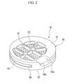
- FIG. 2 is a perspective view of the division member 15 according to the embodiment
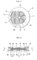
- FIG. 3 is a plan view (top view) of the division member 15 according to the embodiment
- FIG. 4 is a sectional view taken along the line A-A of FIG. 3
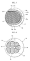
- FIG. 5 is a sectional view taken along the line B-B of FIG. 4
- FIG. 6 is a rear view of the division member 15.
- the first and second division plates 21 and 22 are disposed in the axial direction of the outer cylinder 11 so as to have a gap therebetween.
- the first division plate 21 forms a part of a partition wall of the primary liquid chamber 16
- the second division plate 22 forms a part of a partition wall of the secondary liquid chamber 17.
- Each of division plates 21 and 22 is provided with plural perforation holes 23 which are formed at positions facing the movable plate 18.
- the orifice 19 is provided with an orifice channel 19a which is disposed in the outer peripheral surface thereof so as to extend along the circumferential direction, a first channel 19b which communicates with the orifice channel 19a and the primary liquid chamber 16, and a second channel 19c which communicates with the orifice channel 19a and the secondary liquid chamber 17, and the primary liquid chamber 16 and the secondary liquid chamber 17 communicate with each other through the orifice channels 19a and the first and second channels 19b and 19c.
- the orifice 19 is tuned so as to generate a liquid column resonance at the time of an engine shake vibration having a frequency of about 10 Hz.
- the first division plate 21 and the second division plate 22 are integrally formed, and are formed as a division plate portion 25.
- the division plate portion 25 is formed from, for example, aluminum alloy.
- the division plate portion 25 may be formed from a resin.
- the first division plate 21 and the second division plate 22 are connected to each other through a side wall 27.
- a space surrounded by an inner surface 2 1 a of the first division plate 21, an inner surface 22a of the second division plate 22, and the side wall 27 is formed as a movable plate receiving portion 29 to which the movable plate 18 is inserted.
- the side wall 27 is formed so as to follow the peripheral edge shape of the movable plate 18 inserted between the first division plate 21 and the second division plate 22, and includes a semi-circular cylindrical portion 27b and a pair of flat plate portions 27c which comes into contact with both ends of the semi-circular cylindrical portion 27b.
- the pair of flat plate portions 27c is installed so as to extend up to the outer peripheral surface of the division plate portion 25.
- an opening 28 is formed between the pair of flat plate portions 27c in the outer peripheral surface of the division plate portion 25. That is, it is configured such that the movable plate 18 is able to be inserted from the opening 28 to the movable plate receiving portion 29.
- the orifice channel 19a is formed so as to follow the outer peripheral surface of the side wall 27.
- the inner surface 21a of the first division plate 21 and the inner surface 22a of the second division plate 22 are configured so as to expand and open in a taper shape toward the opening 28 from a blocking end 27a of the side wall 27 facing the opening 28 in the movable plate receiving portion 29.
- the movable plate 18 is formed from, for example, a rubber-like elastic material, and has an outer surface shape following the inner surface shape of the movable plate receiving portion 29. That is, the movable plate 18 is formed in a shape substantially similar to the shape of the movable plate receiving portion 29, and the surface of the movable plate 18 is formed as a tapered surface. With such a configuration, when the movable plate 18 is disposed in the movable plate receiving portion 29, the substantially uniform gaps are provided between the surface of the movable plate 18, the inner surface 21 a of the first division plate 21, and the inner surface 22a of the second division plate 22. In addition, plural spherical convex portions 31 are formed on the surface of the movable plate 18, and are configured to reduce a collision sound generated when the movable plate 18 is vibrated and collides with the respective division plates 21 and 22.
- the movable plate 18 is formed to have a size capable of blocking all perforation holes 23 formed in the first division plate 21 and the second division plate 22.
- a large amplitude of vibration pressure vibration
- both surfaces of the peripheral edge portion of the movable plate 18 are provided with thick portions 18a so as to come into contact with the inner surface 21a of the first division plate 21 and the inner surface 22a of the second division plate 22.
- the anti-vibration device 10 when a vibration (for example, an idle vibration having a frequency of about 30 Hz) having a minute amplitude (for example, ⁇ 0.2 mm or less) acts on the outer cylinder 11 or the attachment member 12 so that a pressure of a liquid inside the primary liquid chamber 16 is changed, the movable plate 18 is vibrated between the inner surface 21 a of the first division plate 21 and the inner surface 22a of the second division plate 22, thereby absorbing and damping the vibration.
- a vibration for example, an idle vibration having a frequency of about 30 Hz
- a minute amplitude for example, ⁇ 0.2 mm or less
- a vibration for example, an engine shake vibration having a frequency of about 10 Hz
- a vibration having an amplitude larger than the above-described minute amplitude
- the movable plate 18 comes into contact with the inner surface 2 1 a of the first division plate 21 or the inner surface 22a of the second division plate 22, and the liquid flows between the primary liquid chamber 16 and the secondary liquid chamber 17 through the orifice 19, thereby absorbing and damping the vibration.
- the first division plate 21 and the second division plate 22 are formed as separate members, when the movable plate 18 is vibrated and comes into contact with the first division plate 21 or the second division plate 22, an original vibration of the first division plate 21 or the second division plate 22 is excited, and both repeatedly come into contact with each other and separate from each other, thereby generating an abnormal noise.
- the first division plate 21 and the second division plate 22 are integrally formed, it is possible to prevent an occurrence of an abnormal noise caused by the contact and separation of the first division plate 21 and the second division plate 22.
- the anti-vibration device 10 including: the outer cylinder 11 which is connected to the vehicle body as the vibration receiving portion, the attachment member 12 which is connected to the engine as the vibration generating portion, the rubber elastic portion 13 which elastically connects the outer cylinder 11 and the attachment member 12, the primary liquid chamber 16 which encloses a liquid therein by using the rubber elastic portion 13 as a part of the partition wall and an internal volume of which changes by deformation of the rubber elastic portion 13, the secondary liquid chamber 17 which encloses a liquid therein by using the diaphragm 14 as a part of the partition wall and is able to expand or contract, the orifice 19 which allows the primary liquid chamber 16 and the secondary liquid chamber 17 to communicate with each other, the division member 15 which is provided between the primary liquid chamber 16 and the secondary liquid chamber 17, and the movable plate 18 which displaces in accordance with the pressure difference between the primary liquid chamber 16 and the secondary liquid chamber 17, wherein the division member 15 includes the first division plate 21 which forms a part of the partition wall of the primary
- the division member 15 is configured such that the movable plate 18 is able to be inserted into the movable plate receiving portion 29 from the opening 28 formed in a part of the side wall 27 connecting the first division plate 21 and the second division plate 22. With such a configuration, it is possible to easily and reliably dispose the movable plate 18 in the movable plate receiving portion 29.
- the orifice 19 is formed at a position not interfering with the movable plate receiving portion 29 in the side wall 27. With such a configuration, since the orifice 19 is formed at a part of the side wall 27 where the movable plate receiving portion 29 is not formed, it is possible to form the division member 15 which efficiently utilizes a space.
- the movable plate receiving portion 29 is configured so as to expand and open in a taper shape toward the opening 28 from the blocking end 27a of the side wall 27 facing the opening 28.
- the outer surface shape of the movable plate 18 is formed in a shape similar to the inner surface shape of the movable plate receiving portion 29.
- the movable plate 18 is formed in a noncircular shape in plan view. With such a configuration, since it is possible to maximally ensure a pressure receiving area of the movable plate 18, it is possible to alleviate an increase in pressure of the primary liquid chamber 16, and thus to suppress an increase in dynamic spring constant.
- the technical scope of the present invention is not limited to the above-described embodiment, and includes the modifications added to the above-described embodiment within the scope not departing from the spirit of the present invention. That is, detailed materials, configurations, or the like in the embodiment are merely an example, and may be appropriately modified.
- the engine is connected to the attachment member and the outer cylinder is connected to the vehicle body, but the engine may be connected to the outer cylinder and the attachment member may be connected to the vehicle body or the anti-vibration device may be installed in other vibration generating portions and vibration receiving portions.
- a configuration has been described in which the movable plate is inserted from the opening, but the movable plate may be inserted from the perforation hole. With such a configuration, it is not necessary to provide the opening or the taper used for an extraction of a mold.
- a configuration has been described in which the movable plate is formed from a rubber-like elastic material, but may be formed from a resin material.
- a configuration has been described in which the entire vibration plate is vibrated, but a part of the movable plate may be fixed to the division plate so that the remainder portion is vibrated.
- the surface of the movable plate is formed in a taper shape, but the front and rear surfaces of the movable plate may be formed as parallel surfaces. With such a configuration, since the movable plate is vibrated while gradually coming into contact with the division plate, it is possible to reduce the rattling sound.
- the orifice is provided on the outside of the movable plate receiving portion, but the movable plate receiving portion and the orifice may be disposed in parallel in the direction of the central axis. With such a configuration, it is possible to ensure the length of the orifice.
Landscapes
- Engineering & Computer Science (AREA)
- General Engineering & Computer Science (AREA)
- Mechanical Engineering (AREA)
- Combined Devices Of Dampers And Springs (AREA)
- Arrangement Or Mounting Of Propulsion Units For Vehicles (AREA)
Applications Claiming Priority (2)
| Application Number | Priority Date | Filing Date | Title |
|---|---|---|---|
| JP2007210685A JP5172243B2 (ja) | 2007-08-13 | 2007-08-13 | 防振装置 |
| PCT/JP2008/062764 WO2009022515A1 (fr) | 2007-08-13 | 2008-07-15 | Dispositif d'isolation de vibrations |
Publications (3)
| Publication Number | Publication Date |
|---|---|
| EP2180208A1 true EP2180208A1 (fr) | 2010-04-28 |
| EP2180208A4 EP2180208A4 (fr) | 2012-11-07 |
| EP2180208B1 EP2180208B1 (fr) | 2014-02-26 |
Family
ID=40350570
Family Applications (1)
| Application Number | Title | Priority Date | Filing Date |
|---|---|---|---|
| EP08778184.5A Not-in-force EP2180208B1 (fr) | 2007-08-13 | 2008-07-15 | Dispositif d'isolation de vibrations |
Country Status (5)
| Country | Link |
|---|---|
| US (1) | US8196700B2 (fr) |
| EP (1) | EP2180208B1 (fr) |
| JP (1) | JP5172243B2 (fr) |
| CN (1) | CN101809313B (fr) |
| WO (1) | WO2009022515A1 (fr) |
Families Citing this family (9)
| Publication number | Priority date | Publication date | Assignee | Title |
|---|---|---|---|---|
| CN102713341B (zh) | 2009-12-10 | 2014-09-03 | 株式会社普利司通 | 液体封入式隔振装置 |
| JP5690233B2 (ja) * | 2011-07-01 | 2015-03-25 | 株式会社ブリヂストン | 防振装置 |
| JP5683395B2 (ja) | 2011-07-01 | 2015-03-11 | 株式会社ブリヂストン | 防振装置 |
| JP5595369B2 (ja) | 2011-12-14 | 2014-09-24 | 東海ゴム工業株式会社 | 流体封入式防振装置 |
| JP5933416B2 (ja) * | 2012-11-07 | 2016-06-08 | 株式会社ブリヂストン | 防振装置の製造方法 |
| JP6429363B2 (ja) * | 2014-06-13 | 2018-11-28 | 株式会社ブリヂストン | 防振装置 |
| JP6395660B2 (ja) | 2015-04-27 | 2018-09-26 | 株式会社ブリヂストン | 防振装置 |
| EP3477149A4 (fr) * | 2016-06-22 | 2019-06-26 | Bridgestone Corporation | Dispositif d'amortissement de vibrations |
| KR101882504B1 (ko) * | 2016-08-18 | 2018-07-27 | 현대자동차주식회사 | 엔진마운트의 노즐판 |
Family Cites Families (21)
| Publication number | Priority date | Publication date | Assignee | Title |
|---|---|---|---|---|
| JPS60175834A (ja) | 1984-02-21 | 1985-09-10 | Honda Motor Co Ltd | 流体入りマウント |
| DE3526686A1 (de) * | 1985-07-25 | 1987-02-05 | Metzeler Kautschuk | Zweikammer-motorlager mit hydraulischer daempfung |
| JPH0788869B2 (ja) * | 1987-05-12 | 1995-09-27 | 本田技研工業株式会社 | 流体封入防振装置 |
| US5139240A (en) * | 1987-05-12 | 1992-08-18 | Honda Giken Kogyo Kabushiki Kaisha | Fluid-filled vibroisolating device |
| US4903591A (en) * | 1989-02-08 | 1990-02-27 | Pitney Bowes Inc. | Mailing machine including improved trip means |
| JPH02132148U (fr) * | 1989-04-07 | 1990-11-02 | ||
| DE3937232A1 (de) * | 1989-11-09 | 1991-05-16 | Freudenberg Carl Fa | Gummilager mit hydraulischer daempfung |
| FR2697604B1 (fr) * | 1992-11-02 | 1995-01-27 | Hutchinson | Perfectionnements aux supports antivibratoires hydrauliques. |
| US5571263A (en) * | 1995-04-14 | 1996-11-05 | General Motors Corporation | Hydraulic engine mount with reduced impulse vibration |
| US7475872B2 (en) * | 2002-03-06 | 2009-01-13 | Delphi Technologies, Inc. | Hydraulic engine mount with center-clamped decoupler |
| US7137491B2 (en) * | 2002-10-29 | 2006-11-21 | Arvinmeritor Technology, Llc | Shock absorber non-vibrating check valve assembly |
| US6910683B2 (en) * | 2003-05-29 | 2005-06-28 | Toyo Tire & Rubber Co., Ltd. | Fluid-sealed anti-vibration device |
| DE602005000091T2 (de) * | 2004-03-12 | 2007-02-22 | Toyo Tire & Rubber Co., Ltd. | Hydraulische schwingungsdämpfende Vorrichtung |
| JP4359889B2 (ja) * | 2004-09-30 | 2009-11-11 | 東海ゴム工業株式会社 | 流体封入式防振装置 |
| JP3943116B2 (ja) * | 2004-10-12 | 2007-07-11 | 東洋ゴム工業株式会社 | 液封入式防振装置 |
| JP2006118583A (ja) | 2004-10-21 | 2006-05-11 | Toyo Tire & Rubber Co Ltd | 液封入式防振装置 |
| US7328888B2 (en) * | 2004-11-24 | 2008-02-12 | Toyo Tire & Rubber Co., Ltd. | Hydraulic antivibration device and hydraulic antivibration assembly containing the same |
| JP2006250339A (ja) | 2005-03-14 | 2006-09-21 | Tokai Rubber Ind Ltd | 流体封入式防振装置 |
| JP4301189B2 (ja) * | 2005-03-17 | 2009-07-22 | 東海ゴム工業株式会社 | 流体封入式防振装置 |
| JP2007177975A (ja) * | 2005-12-28 | 2007-07-12 | Bridgestone Corp | 防振装置 |
| CN100476237C (zh) * | 2006-01-31 | 2009-04-08 | 东海橡胶工业株式会社 | 流体封入式减振装置及其制造方法 |
-
2007
- 2007-08-13 JP JP2007210685A patent/JP5172243B2/ja not_active Expired - Fee Related
-
2008
- 2008-07-15 US US12/673,258 patent/US8196700B2/en active Active
- 2008-07-15 WO PCT/JP2008/062764 patent/WO2009022515A1/fr not_active Ceased
- 2008-07-15 CN CN2008801029404A patent/CN101809313B/zh active Active
- 2008-07-15 EP EP08778184.5A patent/EP2180208B1/fr not_active Not-in-force
Non-Patent Citations (2)
| Title |
|---|
| No further relevant documents disclosed * |
| See also references of WO2009022515A1 * |
Also Published As
| Publication number | Publication date |
|---|---|
| JP2009041761A (ja) | 2009-02-26 |
| JP5172243B2 (ja) | 2013-03-27 |
| CN101809313B (zh) | 2012-08-29 |
| WO2009022515A1 (fr) | 2009-02-19 |
| US20110198149A1 (en) | 2011-08-18 |
| US8196700B2 (en) | 2012-06-12 |
| EP2180208A4 (fr) | 2012-11-07 |
| CN101809313A (zh) | 2010-08-18 |
| EP2180208B1 (fr) | 2014-02-26 |
Similar Documents
| Publication | Publication Date | Title |
|---|---|---|
| EP2180208B1 (fr) | Dispositif d'isolation de vibrations | |
| EP3048332B1 (fr) | Dispositif d'amortissement des vibrations | |
| EP2733381B1 (fr) | Isolateur de vibrations | |
| JP5535958B2 (ja) | 液封入式防振装置 | |
| JP5119018B2 (ja) | 流体封入式防振装置 | |
| JP4741540B2 (ja) | 流体封入式防振装置 | |
| JP4671176B2 (ja) | 流体封入式防振装置 | |
| JP6240482B2 (ja) | 流体封入式防振装置 | |
| JP2013160265A (ja) | 流体封入式防振装置 | |
| JP2007100875A (ja) | 流体封入式防振装置 | |
| CN106030150A (zh) | 隔振装置 | |
| JP2010031988A (ja) | 流体封入式防振装置 | |
| JP5108349B2 (ja) | 流体封入式防振装置 | |
| CN110050143B (zh) | 防振装置 | |
| EP3477146B1 (fr) | Dispositif d'amortissement de vibrations | |
| JP2007271004A (ja) | 流体封入式防振装置 | |
| JP5899039B2 (ja) | 流体封入式防振装置 | |
| JP5899060B2 (ja) | 流体封入式防振装置 | |
| JP2008196508A (ja) | 流体封入式防振装置 | |
| JP5852925B2 (ja) | 流体封入式防振装置 | |
| JP5986515B2 (ja) | 流体封入式防振装置 | |
| JP5926108B2 (ja) | 流体封入式防振装置 | |
| JP2008157384A (ja) | 液体封入式防振装置及びその製造方法 | |
| JP2014152859A (ja) | 流体封入式防振装置 | |
| JP2006336719A (ja) | 防振装置 |
Legal Events
| Date | Code | Title | Description |
|---|---|---|---|
| PUAI | Public reference made under article 153(3) epc to a published international application that has entered the european phase |
Free format text: ORIGINAL CODE: 0009012 |
|
| 17P | Request for examination filed |
Effective date: 20100218 |
|
| AK | Designated contracting states |
Kind code of ref document: A1 Designated state(s): AT BE BG CH CY CZ DE DK EE ES FI FR GB GR HR HU IE IS IT LI LT LU LV MC MT NL NO PL PT RO SE SI SK TR |
|
| AX | Request for extension of the european patent |
Extension state: AL BA MK RS |
|
| DAX | Request for extension of the european patent (deleted) | ||
| A4 | Supplementary search report drawn up and despatched |
Effective date: 20121009 |
|
| RIC1 | Information provided on ipc code assigned before grant |
Ipc: B60K 5/12 20060101ALI20121003BHEP Ipc: F16F 13/06 20060101ALI20121003BHEP Ipc: F16F 13/10 20060101ALI20121003BHEP Ipc: F16F 13/18 20060101AFI20121003BHEP |
|
| GRAP | Despatch of communication of intention to grant a patent |
Free format text: ORIGINAL CODE: EPIDOSNIGR1 |
|
| INTG | Intention to grant announced |
Effective date: 20130829 |
|
| GRAS | Grant fee paid |
Free format text: ORIGINAL CODE: EPIDOSNIGR3 |
|
| GRAA | (expected) grant |
Free format text: ORIGINAL CODE: 0009210 |
|
| AK | Designated contracting states |
Kind code of ref document: B1 Designated state(s): AT BE BG CH CY CZ DE DK EE ES FI FR GB GR HR HU IE IS IT LI LT LU LV MC MT NL NO PL PT RO SE SI SK TR |
|
| REG | Reference to a national code |
Ref country code: GB Ref legal event code: FG4D |
|
| REG | Reference to a national code |
Ref country code: CH Ref legal event code: EP |
|
| REG | Reference to a national code |
Ref country code: AT Ref legal event code: REF Ref document number: 653799 Country of ref document: AT Kind code of ref document: T Effective date: 20140315 |
|
| REG | Reference to a national code |
Ref country code: IE Ref legal event code: FG4D |
|
| REG | Reference to a national code |
Ref country code: DE Ref legal event code: R096 Ref document number: 602008030457 Country of ref document: DE Effective date: 20140410 |
|
| REG | Reference to a national code |
Ref country code: NL Ref legal event code: VDEP Effective date: 20140226 |
|
| REG | Reference to a national code |
Ref country code: AT Ref legal event code: MK05 Ref document number: 653799 Country of ref document: AT Kind code of ref document: T Effective date: 20140226 |
|
| REG | Reference to a national code |
Ref country code: LT Ref legal event code: MG4D |
|
| PG25 | Lapsed in a contracting state [announced via postgrant information from national office to epo] |
Ref country code: IS Free format text: LAPSE BECAUSE OF FAILURE TO SUBMIT A TRANSLATION OF THE DESCRIPTION OR TO PAY THE FEE WITHIN THE PRESCRIBED TIME-LIMIT Effective date: 20140626 Ref country code: NO Free format text: LAPSE BECAUSE OF FAILURE TO SUBMIT A TRANSLATION OF THE DESCRIPTION OR TO PAY THE FEE WITHIN THE PRESCRIBED TIME-LIMIT Effective date: 20140526 Ref country code: LT Free format text: LAPSE BECAUSE OF FAILURE TO SUBMIT A TRANSLATION OF THE DESCRIPTION OR TO PAY THE FEE WITHIN THE PRESCRIBED TIME-LIMIT Effective date: 20140226 |
|
| PG25 | Lapsed in a contracting state [announced via postgrant information from national office to epo] |
Ref country code: AT Free format text: LAPSE BECAUSE OF FAILURE TO SUBMIT A TRANSLATION OF THE DESCRIPTION OR TO PAY THE FEE WITHIN THE PRESCRIBED TIME-LIMIT Effective date: 20140226 Ref country code: CY Free format text: LAPSE BECAUSE OF FAILURE TO SUBMIT A TRANSLATION OF THE DESCRIPTION OR TO PAY THE FEE WITHIN THE PRESCRIBED TIME-LIMIT Effective date: 20140226 Ref country code: NL Free format text: LAPSE BECAUSE OF FAILURE TO SUBMIT A TRANSLATION OF THE DESCRIPTION OR TO PAY THE FEE WITHIN THE PRESCRIBED TIME-LIMIT Effective date: 20140226 Ref country code: SE Free format text: LAPSE BECAUSE OF FAILURE TO SUBMIT A TRANSLATION OF THE DESCRIPTION OR TO PAY THE FEE WITHIN THE PRESCRIBED TIME-LIMIT Effective date: 20140226 Ref country code: PT Free format text: LAPSE BECAUSE OF FAILURE TO SUBMIT A TRANSLATION OF THE DESCRIPTION OR TO PAY THE FEE WITHIN THE PRESCRIBED TIME-LIMIT Effective date: 20140626 Ref country code: FI Free format text: LAPSE BECAUSE OF FAILURE TO SUBMIT A TRANSLATION OF THE DESCRIPTION OR TO PAY THE FEE WITHIN THE PRESCRIBED TIME-LIMIT Effective date: 20140226 |
|
| PG25 | Lapsed in a contracting state [announced via postgrant information from national office to epo] |
Ref country code: BE Free format text: LAPSE BECAUSE OF FAILURE TO SUBMIT A TRANSLATION OF THE DESCRIPTION OR TO PAY THE FEE WITHIN THE PRESCRIBED TIME-LIMIT Effective date: 20140226 Ref country code: HR Free format text: LAPSE BECAUSE OF FAILURE TO SUBMIT A TRANSLATION OF THE DESCRIPTION OR TO PAY THE FEE WITHIN THE PRESCRIBED TIME-LIMIT Effective date: 20140226 Ref country code: LV Free format text: LAPSE BECAUSE OF FAILURE TO SUBMIT A TRANSLATION OF THE DESCRIPTION OR TO PAY THE FEE WITHIN THE PRESCRIBED TIME-LIMIT Effective date: 20140226 |
|
| PG25 | Lapsed in a contracting state [announced via postgrant information from national office to epo] |
Ref country code: DK Free format text: LAPSE BECAUSE OF FAILURE TO SUBMIT A TRANSLATION OF THE DESCRIPTION OR TO PAY THE FEE WITHIN THE PRESCRIBED TIME-LIMIT Effective date: 20140226 Ref country code: RO Free format text: LAPSE BECAUSE OF FAILURE TO SUBMIT A TRANSLATION OF THE DESCRIPTION OR TO PAY THE FEE WITHIN THE PRESCRIBED TIME-LIMIT Effective date: 20140226 Ref country code: EE Free format text: LAPSE BECAUSE OF FAILURE TO SUBMIT A TRANSLATION OF THE DESCRIPTION OR TO PAY THE FEE WITHIN THE PRESCRIBED TIME-LIMIT Effective date: 20140226 Ref country code: CZ Free format text: LAPSE BECAUSE OF FAILURE TO SUBMIT A TRANSLATION OF THE DESCRIPTION OR TO PAY THE FEE WITHIN THE PRESCRIBED TIME-LIMIT Effective date: 20140226 |
|
| REG | Reference to a national code |
Ref country code: DE Ref legal event code: R097 Ref document number: 602008030457 Country of ref document: DE |
|
| PG25 | Lapsed in a contracting state [announced via postgrant information from national office to epo] |
Ref country code: ES Free format text: LAPSE BECAUSE OF FAILURE TO SUBMIT A TRANSLATION OF THE DESCRIPTION OR TO PAY THE FEE WITHIN THE PRESCRIBED TIME-LIMIT Effective date: 20140226 Ref country code: SK Free format text: LAPSE BECAUSE OF FAILURE TO SUBMIT A TRANSLATION OF THE DESCRIPTION OR TO PAY THE FEE WITHIN THE PRESCRIBED TIME-LIMIT Effective date: 20140226 Ref country code: PL Free format text: LAPSE BECAUSE OF FAILURE TO SUBMIT A TRANSLATION OF THE DESCRIPTION OR TO PAY THE FEE WITHIN THE PRESCRIBED TIME-LIMIT Effective date: 20140226 |
|
| PLBE | No opposition filed within time limit |
Free format text: ORIGINAL CODE: 0009261 |
|
| STAA | Information on the status of an ep patent application or granted ep patent |
Free format text: STATUS: NO OPPOSITION FILED WITHIN TIME LIMIT |
|
| 26N | No opposition filed |
Effective date: 20141127 |
|
| PG25 | Lapsed in a contracting state [announced via postgrant information from national office to epo] |
Ref country code: LU Free format text: LAPSE BECAUSE OF FAILURE TO SUBMIT A TRANSLATION OF THE DESCRIPTION OR TO PAY THE FEE WITHIN THE PRESCRIBED TIME-LIMIT Effective date: 20140715 |
|
| REG | Reference to a national code |
Ref country code: CH Ref legal event code: PL |
|
| REG | Reference to a national code |
Ref country code: DE Ref legal event code: R097 Ref document number: 602008030457 Country of ref document: DE Effective date: 20141127 |
|
| GBPC | Gb: european patent ceased through non-payment of renewal fee |
Effective date: 20140715 |
|
| REG | Reference to a national code |
Ref country code: IE Ref legal event code: MM4A |
|
| PG25 | Lapsed in a contracting state [announced via postgrant information from national office to epo] |
Ref country code: LI Free format text: LAPSE BECAUSE OF NON-PAYMENT OF DUE FEES Effective date: 20140731 Ref country code: CH Free format text: LAPSE BECAUSE OF NON-PAYMENT OF DUE FEES Effective date: 20140731 |
|
| PG25 | Lapsed in a contracting state [announced via postgrant information from national office to epo] |
Ref country code: GB Free format text: LAPSE BECAUSE OF NON-PAYMENT OF DUE FEES Effective date: 20140715 Ref country code: SI Free format text: LAPSE BECAUSE OF FAILURE TO SUBMIT A TRANSLATION OF THE DESCRIPTION OR TO PAY THE FEE WITHIN THE PRESCRIBED TIME-LIMIT Effective date: 20140226 |
|
| PG25 | Lapsed in a contracting state [announced via postgrant information from national office to epo] |
Ref country code: IE Free format text: LAPSE BECAUSE OF NON-PAYMENT OF DUE FEES Effective date: 20140715 |
|
| PG25 | Lapsed in a contracting state [announced via postgrant information from national office to epo] |
Ref country code: MC Free format text: LAPSE BECAUSE OF FAILURE TO SUBMIT A TRANSLATION OF THE DESCRIPTION OR TO PAY THE FEE WITHIN THE PRESCRIBED TIME-LIMIT Effective date: 20140226 |
|
| PG25 | Lapsed in a contracting state [announced via postgrant information from national office to epo] |
Ref country code: BG Free format text: LAPSE BECAUSE OF FAILURE TO SUBMIT A TRANSLATION OF THE DESCRIPTION OR TO PAY THE FEE WITHIN THE PRESCRIBED TIME-LIMIT Effective date: 20140226 |
|
| PG25 | Lapsed in a contracting state [announced via postgrant information from national office to epo] |
Ref country code: GR Free format text: LAPSE BECAUSE OF FAILURE TO SUBMIT A TRANSLATION OF THE DESCRIPTION OR TO PAY THE FEE WITHIN THE PRESCRIBED TIME-LIMIT Effective date: 20140527 Ref country code: MT Free format text: LAPSE BECAUSE OF FAILURE TO SUBMIT A TRANSLATION OF THE DESCRIPTION OR TO PAY THE FEE WITHIN THE PRESCRIBED TIME-LIMIT Effective date: 20140226 |
|
| REG | Reference to a national code |
Ref country code: FR Ref legal event code: PLFP Year of fee payment: 9 |
|
| PG25 | Lapsed in a contracting state [announced via postgrant information from national office to epo] |
Ref country code: TR Free format text: LAPSE BECAUSE OF FAILURE TO SUBMIT A TRANSLATION OF THE DESCRIPTION OR TO PAY THE FEE WITHIN THE PRESCRIBED TIME-LIMIT Effective date: 20140226 Ref country code: HU Free format text: LAPSE BECAUSE OF FAILURE TO SUBMIT A TRANSLATION OF THE DESCRIPTION OR TO PAY THE FEE WITHIN THE PRESCRIBED TIME-LIMIT; INVALID AB INITIO Effective date: 20080715 |
|
| REG | Reference to a national code |
Ref country code: FR Ref legal event code: PLFP Year of fee payment: 10 |
|
| REG | Reference to a national code |
Ref country code: FR Ref legal event code: PLFP Year of fee payment: 11 |
|
| PGFP | Annual fee paid to national office [announced via postgrant information from national office to epo] |
Ref country code: IT Payment date: 20190730 Year of fee payment: 12 |
|
| PG25 | Lapsed in a contracting state [announced via postgrant information from national office to epo] |
Ref country code: IT Free format text: LAPSE BECAUSE OF NON-PAYMENT OF DUE FEES Effective date: 20200715 |
|
| REG | Reference to a national code |
Ref country code: DE Ref legal event code: R081 Ref document number: 602008030457 Country of ref document: DE Owner name: PROSPIRA CORPORATION, JP Free format text: FORMER OWNER: BRIDGESTONE CORP., TOKIO/TOKYO, JP Ref country code: DE Ref document number: 602008030457 Representative=s name: DR. SOLF & ZAPF PATENT- UND RECHTSANWALTS PART, DE Ref legal event code: R082 Country of ref document: DE |
|
| REG | Reference to a national code |
Ref country code: DE Ref legal event code: R082 Ref document number: 602008030457 Country of ref document: DE |
|
| PGFP | Annual fee paid to national office [announced via postgrant information from national office to epo] |
Ref country code: DE Payment date: 20240719 Year of fee payment: 17 |
|
| PGFP | Annual fee paid to national office [announced via postgrant information from national office to epo] |
Ref country code: FR Payment date: 20240729 Year of fee payment: 17 |
|
| REG | Reference to a national code |
Ref country code: DE Ref legal event code: R119 Ref document number: 602008030457 Country of ref document: DE |
|
| PG25 | Lapsed in a contracting state [announced via postgrant information from national office to epo] |
Ref country code: DE Free format text: LAPSE BECAUSE OF NON-PAYMENT OF DUE FEES Effective date: 20260203 |
|
| PG25 | Lapsed in a contracting state [announced via postgrant information from national office to epo] |
Ref country code: FR Free format text: LAPSE BECAUSE OF NON-PAYMENT OF DUE FEES Effective date: 20250731 |