EP2180336B1 - Capteurs de radar à micro-ondes et à onde millimétriques - Google Patents
Capteurs de radar à micro-ondes et à onde millimétriques Download PDFInfo
- Publication number
- EP2180336B1 EP2180336B1 EP09173346.9A EP09173346A EP2180336B1 EP 2180336 B1 EP2180336 B1 EP 2180336B1 EP 09173346 A EP09173346 A EP 09173346A EP 2180336 B1 EP2180336 B1 EP 2180336B1
- Authority
- EP
- European Patent Office
- Prior art keywords
- sensor
- central processor
- radar
- antenna
- signal
- Prior art date
- Legal status (The legal status is an assumption and is not a legal conclusion. Google has not performed a legal analysis and makes no representation as to the accuracy of the status listed.)
- Active
Links
Images


Classifications
-
- G—PHYSICS
- G01—MEASURING; TESTING
- G01S—RADIO DIRECTION-FINDING; RADIO NAVIGATION; DETERMINING DISTANCE OR VELOCITY BY USE OF RADIO WAVES; LOCATING OR PRESENCE-DETECTING BY USE OF THE REFLECTION OR RERADIATION OF RADIO WAVES; ANALOGOUS ARRANGEMENTS USING OTHER WAVES
- G01S13/00—Systems using the reflection or reradiation of radio waves, e.g. radar systems; Analogous systems using reflection or reradiation of waves whose nature or wavelength is irrelevant or unspecified
- G01S13/88—Radar or analogous systems specially adapted for specific applications
- G01S13/93—Radar or analogous systems specially adapted for specific applications for anti-collision purposes
- G01S13/931—Radar or analogous systems specially adapted for specific applications for anti-collision purposes of land vehicles
-
- G—PHYSICS
- G01—MEASURING; TESTING
- G01S—RADIO DIRECTION-FINDING; RADIO NAVIGATION; DETERMINING DISTANCE OR VELOCITY BY USE OF RADIO WAVES; LOCATING OR PRESENCE-DETECTING BY USE OF THE REFLECTION OR RERADIATION OF RADIO WAVES; ANALOGOUS ARRANGEMENTS USING OTHER WAVES
- G01S13/00—Systems using the reflection or reradiation of radio waves, e.g. radar systems; Analogous systems using reflection or reradiation of waves whose nature or wavelength is irrelevant or unspecified
- G01S13/02—Systems using reflection of radio waves, e.g. primary radar systems; Analogous systems
- G01S13/06—Systems determining position data of a target
- G01S13/08—Systems for measuring distance only
- G01S13/32—Systems for measuring distance only using transmission of continuous waves, whether amplitude-, frequency-, or phase-modulated, or unmodulated
- G01S13/34—Systems for measuring distance only using transmission of continuous waves, whether amplitude-, frequency-, or phase-modulated, or unmodulated using transmission of continuous, frequency-modulated waves while heterodyning the received signal, or a signal derived therefrom, with a locally-generated signal related to the contemporaneously transmitted signal
- G01S13/343—Systems for measuring distance only using transmission of continuous waves, whether amplitude-, frequency-, or phase-modulated, or unmodulated using transmission of continuous, frequency-modulated waves while heterodyning the received signal, or a signal derived therefrom, with a locally-generated signal related to the contemporaneously transmitted signal using sawtooth modulation
-
- G—PHYSICS
- G01—MEASURING; TESTING
- G01S—RADIO DIRECTION-FINDING; RADIO NAVIGATION; DETERMINING DISTANCE OR VELOCITY BY USE OF RADIO WAVES; LOCATING OR PRESENCE-DETECTING BY USE OF THE REFLECTION OR RERADIATION OF RADIO WAVES; ANALOGOUS ARRANGEMENTS USING OTHER WAVES
- G01S13/00—Systems using the reflection or reradiation of radio waves, e.g. radar systems; Analogous systems using reflection or reradiation of waves whose nature or wavelength is irrelevant or unspecified
- G01S13/87—Combinations of radar systems, e.g. primary radar and secondary radar
-
- G—PHYSICS
- G01—MEASURING; TESTING
- G01S—RADIO DIRECTION-FINDING; RADIO NAVIGATION; DETERMINING DISTANCE OR VELOCITY BY USE OF RADIO WAVES; LOCATING OR PRESENCE-DETECTING BY USE OF THE REFLECTION OR RERADIATION OF RADIO WAVES; ANALOGOUS ARRANGEMENTS USING OTHER WAVES
- G01S7/00—Details of systems according to groups G01S13/00, G01S15/00, G01S17/00
- G01S7/02—Details of systems according to groups G01S13/00, G01S15/00, G01S17/00 of systems according to group G01S13/00
- G01S7/023—Interference mitigation, e.g. reducing or avoiding non-intentional interference with other HF-transmitters, base station transmitters for mobile communication or other radar systems, e.g. using electro-magnetic interference [EMI] reduction techniques
-
- G—PHYSICS
- G01—MEASURING; TESTING
- G01S—RADIO DIRECTION-FINDING; RADIO NAVIGATION; DETERMINING DISTANCE OR VELOCITY BY USE OF RADIO WAVES; LOCATING OR PRESENCE-DETECTING BY USE OF THE REFLECTION OR RERADIATION OF RADIO WAVES; ANALOGOUS ARRANGEMENTS USING OTHER WAVES
- G01S7/00—Details of systems according to groups G01S13/00, G01S15/00, G01S17/00
- G01S7/02—Details of systems according to groups G01S13/00, G01S15/00, G01S17/00 of systems according to group G01S13/00
- G01S7/023—Interference mitigation, e.g. reducing or avoiding non-intentional interference with other HF-transmitters, base station transmitters for mobile communication or other radar systems, e.g. using electro-magnetic interference [EMI] reduction techniques
- G01S7/0232—Avoidance by frequency multiplex
-
- G—PHYSICS
- G01—MEASURING; TESTING
- G01S—RADIO DIRECTION-FINDING; RADIO NAVIGATION; DETERMINING DISTANCE OR VELOCITY BY USE OF RADIO WAVES; LOCATING OR PRESENCE-DETECTING BY USE OF THE REFLECTION OR RERADIATION OF RADIO WAVES; ANALOGOUS ARRANGEMENTS USING OTHER WAVES
- G01S7/00—Details of systems according to groups G01S13/00, G01S15/00, G01S17/00
- G01S7/02—Details of systems according to groups G01S13/00, G01S15/00, G01S17/00 of systems according to group G01S13/00
- G01S7/023—Interference mitigation, e.g. reducing or avoiding non-intentional interference with other HF-transmitters, base station transmitters for mobile communication or other radar systems, e.g. using electro-magnetic interference [EMI] reduction techniques
- G01S7/0236—Avoidance by space multiplex
-
- G—PHYSICS
- G01—MEASURING; TESTING
- G01S—RADIO DIRECTION-FINDING; RADIO NAVIGATION; DETERMINING DISTANCE OR VELOCITY BY USE OF RADIO WAVES; LOCATING OR PRESENCE-DETECTING BY USE OF THE REFLECTION OR RERADIATION OF RADIO WAVES; ANALOGOUS ARRANGEMENTS USING OTHER WAVES
- G01S7/00—Details of systems according to groups G01S13/00, G01S15/00, G01S17/00
- G01S7/02—Details of systems according to groups G01S13/00, G01S15/00, G01S17/00 of systems according to group G01S13/00
- G01S7/35—Details of non-pulse systems
-
- G—PHYSICS
- G01—MEASURING; TESTING
- G01S—RADIO DIRECTION-FINDING; RADIO NAVIGATION; DETERMINING DISTANCE OR VELOCITY BY USE OF RADIO WAVES; LOCATING OR PRESENCE-DETECTING BY USE OF THE REFLECTION OR RERADIATION OF RADIO WAVES; ANALOGOUS ARRANGEMENTS USING OTHER WAVES
- G01S13/00—Systems using the reflection or reradiation of radio waves, e.g. radar systems; Analogous systems using reflection or reradiation of waves whose nature or wavelength is irrelevant or unspecified
- G01S13/88—Radar or analogous systems specially adapted for specific applications
- G01S13/93—Radar or analogous systems specially adapted for specific applications for anti-collision purposes
- G01S13/931—Radar or analogous systems specially adapted for specific applications for anti-collision purposes of land vehicles
- G01S2013/9321—Velocity regulation, e.g. cruise control
Definitions
- MMW millimeterwave
- the RF implementation of the MMW Radar subsystems has either been overly complex (frequency multiplication systems) or overly simple with poor RF performance (MMW Oscillator directly connected to an antenna and modulated). Both systems generate very high phase noise and varying modulation characteristics over time and environmental changes.
- U.S. patent 7,324,039 to Boltovets et al. attempts to generate a MMW radar signal by frequency multiplication of an open loop X band Voltage Controlled Oscillator. This choice for FM/CW modulation also directly multiplies any modulation non-linearity and causes phase noise to increase by a factor of 20 Log N where N is the multiplication factor. Both factors significantly degrade the performance of the resulting system.
- Document EP0717290 discloses a plurality of radar devices provided along the periphery of a vehicle.
- the present invention provides a system as defined in claim1.
- the system may include the features of any one or more of dependent claims 2 to 4.
- the present invention also provides a method as defined in claim 5.
- the method may include the features of any one or more of claims 6 to 9.
- the present invention provides a low cost means to achieve the needed sensitivity of the microwave or MMW radar sensors with low phase noise and accurate modulation at the lowest possible cost of signal generation and signal processing.
- the proposed system has the advantage being scaled in size from one sensor to many sensors, all served by a common control and signal processing system.
- An example radar system includes a processor and a plurality of transceivers having antenna(e).
- the transceivers and/or antennas of the transceivers are located at various points around the vehicle.
- the transceivers include receive and transmit electronics that are in signal communication with the corresponding antenna for outputting radar signals.
- the transmit electronics include a voltage controlled oscillator (VCO), a dielectric resonator oscillator (DRO), a phase locked loop (PLL) component and a direct digital synthesizer (DDS).
- VCO voltage controlled oscillator
- DRO dielectric resonator oscillator
- PLL phase locked loop
- DDS direct digital synthesizer
- the receive electronics receive from the antenna any radar reflections corresponding to the outputted radar signals and send signals associated with the radar reflections to the processor.
- the processor generates output signals based on the signals received from the plurality of transceivers.
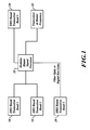
- FIGURE 1 is a block diagram of a system implemented on a vehicle or a building
- FIGURES 2 and 3 are system diagrams of example transceivers formed in accordance with embodiments of the present invention.
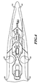
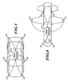
- FIGURES 4-6 illustrate the systems of FIGURE 1 implemented on various vehicles.
- the present invention provides a system 20 that includes a master signal processor 22 in signal communication with one or more radar components 24.
- the radar components 24 translate an operating frequency to Microwave or millimeterwave (MMW) range by mixing it with an "open loop" oscillator that operates at MMW frequencies that offers frequency stability over time, temperature and vibration, such as a Dielectric Resonator Oscillator (DRO) (example DROs are produced by Honeywell Inc.).
- DRO Dielectric Resonator Oscillator
- An array of radar components 24 are mounted to a vehicle or building and are controlled by the processor 22.
- the processor 22 determines if any of the radar components 24 have sensed any objects and outputs that determination to an operator.
- the processor 22 provides control signals for altering the modulation or antenna scanning at each radar component 24.
- the processor 22 is programmable such that a sequence of modulation rates can be applied to the radar components 24 so that each is optimized for its application and location on a vehicle.
- the results measured by adjacent radar components 24 can be directly compared to generate additional intelligence about the dangers or situation around the vehicle.
- the processor 22 permits the coordination of the multiple sensors (the radar components 24) - causing them to be synchronous and have specific offset frequencies in order to prevent jamming /interfering with each other.
- the processor 22 also has the ability to "sweep" from sensor to sensor to collect an overall image/data of the surroundings by interrogating them sequentially.
- the processor 22 can also dwell at one sensor (the radar components 24) for as long as needed or jump between sensors as required as well with no particular pattern, according to the surveillance needs.
- an example radar component 24-1 includes a suitable microwave or MMW voltage controlled oscillator (VCO) 40 and a DRO 42 that is tuned to a frequency at a predefined level below the lowest expected VCO frequency.
- VCO microwave or MMW voltage controlled oscillator
- DRO digital filter
- the output of the VCO and the DRO are mixed at a mixer 48 to generate an intermediate (IF) that may be divided down to produce an input signal to a phase locked loop (PLL) chip 50, such as that produced the ADF 4111 PLL manufactured by Analog Devices.
- PLL chip 50 provides some frequency division and a Phase/Frequency detector and a charge pump are used to close the PLL chip 50.
- the PLL chip 50 includes the charge pump, phase/freq detector and frequency division component.
- the PLL chip 50 provides desired linearity and low phase noise present in both the DRO and VCO of approximately (-100dBc/Hz at 100 KHz).
- the radar component 24-1 is a dual antenna transceiver.
- a radar component 24-2 is a single antenna transceiver.
- the receiver and transmitter components within the radar components 24-1 and 24-2 are the same except that the single antenna transceiver includes a circulator device attached to the antenna.
- a direct digital synthesizer (DDS) 52 provides a reference input signal to the PLL chip 50 based on signal from a clock 54.
- the clock 54 is a 125 MHz clock that causes the DDS 52 to produce the reference input signal at 25-31.25 MHz.
- the DDS frequencies are independent of the VCO and of the MMW operating frequency.
- the output of the PLL chip 50 is amplified and filtered then input to the VCO 40.
- the VCO 40 generates a signal that is amplified, filtered by a band pass filter, sent to the mixer 48 and then sent to a transmit antenna and receive antenna mixer via couplers.
- the RF input to the mixer 48 is a sample of the entire transmitted bandwidth of the MMW sensor. So for example, if the sensor transmits between 24.00 GHz and 24.20 GHz (200 MHz BW) then the input to 48 RF port is 24.00 to 24.20 GHz.
- the exact bandwidth depends on the frequency division and the programmed frequency division within the PLL chip itself. So this system is programmable for many frequency ranges.
- a 24 GHz Radar that has FM/CW modulation between 24.00 and 24.20 GHz select a VCO that tunes from F (24.00GHz) to F+0.2 GHz (24.2GHz). Then one chooses a DRO at F-0.8 (23.2 GHz).
- the difference of the two frequencies is 0.8 to 1.0 GHz.
- Those difference frequencies of 0.8 to 1.0 GHz are the input to the PLL where it is divided by 32 within the PLL chip (e.g., ADF 4111) to produce 25 - 31.25 MHz that is in turn compared to the DDS input over the same frequency range.
- the use of the DRO to create a modest IF frequency range near 1 GHz is critical to permitting very low frequency divider ratios or the elimination of frequency multiplication modules.
- the DRO preserves very low phase noise that would otherwise be substantially higher with other methods.
- the IF frequency range at the input to the PLL chip (ADF 4111) would increase from the original 0.8 to 1.0 GHz to 0.8 to 1,2 GHz. This IF frequency range will track the actual bandwidth of the modulated millimeter wave frequency source.
- carbon fiber composites enclose each of the radar components 24 to provide exceptionally strong and EMI/EMC absorption that prevents the radar components 24 from jamming or being jammed by other sensors on other vehicles etc. and at the same time provides physical protection from an outdoor environment.
- a receive side of the radar components 24-1 and 24-2 includes common radar receiver components.
- the received signals are converted to digital then sent to the master processor 22 for analysis.
- Communication between the components 24-1 and 24-2 can be done over a data bus, fiber optic coils, wirelessly or by any other comparable means.
- the sensors operate in the same band (i.e., 24 GHz, 77 GHz, 35 GHz, 95 GHz) but not at the same exact frequency ranges. Because the master controller 22 can command the sensors 24 it can do two things: 1) command specific frequency ranges for the FM/CW modulation that is offset in frequency from any other sensor 24 by at least 1 to 2 times the IF frequency of the receiver (receiver mixer output); 2) it can synchronize the start and stop times of the sensors to be exact so that the programmed frequency difference between the sensors is always maintained throughout the frequency modulation period. That exactly prevents jamming or interaction among the sensors.
- FIGURE 4 illustrates a top, partial view of a ship having four radar components 24 mounted on exterior surfaces of the ship and the master processor 22 being located to receive data from the radar components 24.
- FIGURES 5 and 6 illustrate similar systems mounted on a car and an aircraft.
- the system 20 is adaptable to any legal radar band up to 95 GHz with a common digitally synthesized control loop. It can go higher than 95 GHz. There is no fundamental limitation at 95GHz except that most typical operating bands end there. When you get to 100 GHz and above you get close to bands known as "Near IR" - meaning that you are approaching the wavelengths of Infrared radiation.
Landscapes
- Engineering & Computer Science (AREA)
- Radar, Positioning & Navigation (AREA)
- Remote Sensing (AREA)
- Computer Networks & Wireless Communication (AREA)
- Physics & Mathematics (AREA)
- General Physics & Mathematics (AREA)
- Electromagnetism (AREA)
- Radar Systems Or Details Thereof (AREA)
Claims (9)
- Système radar placé sur un véhicule, le système comprenant :un processeur central (22) ;une pluralité d'émetteurs-récepteurs capteurs (24) placés en divers points autour du véhicule, la pluralité d'émetteurs-récepteurs capteurs étant en communication par signaux avec le processeur central, la pluralité d'émetteurs-récepteurs capteurs comprenant :au moins une antenne ;de l'électronique de réception en communication par signaux avec ladite au moins une antenne et le processeur ; etde l'électronique d'émission en communication par signaux avec ladite au moins une antenne, l'électronique d'émission étant configurée pour fournir des signaux radar par le biais de ladite au moins une antenne, l'électronique d'émission comprenant :un oscillateur commandé par tension (VCO) (40) ;un oscillateur à résonateur diélectrique (DRO) (42) ;un composant à boucle à verrouillage de phase (PLL) (50) ;un synthétiseur numérique direct (DDS) (52) ;un filtre à boucle ;un amplificateur ;un coupleur configuré pour extraire une partie d'un signal envoyé par le VCO à ladite au moins une antenne ;un mélangeur (48) configuré pour mélanger le signal extrait avec un signal produit par le DRO ;un filtre passe-bas configuré pour filtrer les signaux mélangés ; etun diviseur configuré pour diviser le signal filtré par le filtre passe-bas ;le composant à PLL (50) recevant la sortie du diviseur et du DDS,la sortie du composant à PLL (50) étant envoyée au VCO (40) après être passée par l'amplificateur et le filtre à boucle,l'électronique de réception étant configurée pour recevoir de ladite au moins une antenne toutes réflexions radar correspondant aux signaux radar fournis et pour envoyer au processeur des signaux associés aux réflexions radar,le processeur central étant configuré pour générer des signaux de sortie en fonction des signaux reçus depuis la pluralité d'émetteurs-récepteurs capteurs.
- Système selon la revendication 1, dans lequel l'électronique d'émission comprend en outre une horloge (54) configurée pour générer une entrée appliquée au DDS (52).
- Système selon la revendication 1, dans lequel le processeur central est configuré pour coordonner la pluralité d'émetteurs-récepteurs capteurs pour faire en sorte que la pluralité d'émetteurs-récepteurs capteurs soient synchrones et possèdent des fréquences décalées spécifiques dans le but d'empêcher tout brouillage mutuel ou toute interférence mutuelle.
- Système selon la revendication 1, dans lequel le processeur central est configuré pour effectuer un balayage d'un émetteur-récepteur capteur à un autre dans le but de recueillir des données et générer une appréciation de l'environnement du véhicule, pour s'attarder sur un des émetteurs-récepteurs capteurs en fonction d'un protocole prédéfini ou d'une requête manuelle ou pour effectuer des sauts entre les émetteurs-récepteurs capteurs en fonction d'un protocole prédéfini ou d'une requête manuelle.
- Procédé de détection de cibles placées autour d'un véhicule, le procédé comprenant les étapes consistant à :au niveau de chacun d'une pluralité d'émetteurs-récepteurs capteurs :émettre des signaux radar par le biais d'au moins une antenne, l'étape consistant à émettre les signaux radar comprenant les étapes consistant à :mélanger un signal produit par un oscillateur à résonateur diélectrique (DRO) avec un signal produit par un oscillateur commandé par tension (VCO) ;diviser la sortie du mélangeur pour produire un signal d'entrée appliqué à un composant à boucle à verrouillage de phase (PLL) ;appliquer un signal de référence produit par un synthétiseur numérique direct (DDS) au composant à PPL ; etamplifier et filtrer une sortie du composant à PLL avant de l'envoyer au VCO ;recevoir depuis ladite au moins une antenne toutes réflexions radar correspondant aux signaux radar émis ;envoyer à un processeur central des signaux associés aux réflexions radar reçues ; etgénérer, au niveau du processeur central, des signaux de sortie en fonction des signaux envoyés.
- Procédé selon la revendication 5, dans lequel l'étape consistant à appliquer le signal de référence comprenant l'étape consistant à appliquer un signal d'horloge au DDS.
- Procédé selon la revendication 5, comprenant en outre l'étape consistant à coordonner, au niveau du processeur central, la pluralité d'émetteurs-récepteurs capteurs pour faire en sorte que la pluralité d'émetteurs-récepteurs capteurs soient synchrones et possèdent des fréquences décalées spécifiques dans le but d'empêcher tout brouillage mutuel ou toute interférence mutuelle.
- Procédé selon la revendication 5, comprenant en outre l'étape consistant à faire effectuer un balayage par le processeur central pour qu'il reçoive d'un émetteur-récepteur capteur à un autre dans le but de recueillir des données et générer des informations relatives à une appréciation de l'environnement du véhicule.
- Procédé selon la revendication 5, comprenant en outre l'étape consistant à faire s'attarder le processeur central sur un des émetteurs-récepteurs capteurs en fonction d'un protocole prédéfini ou d'une requête manuelle, ou à faire effectuer au processeur central des sauts entre les émetteurs-récepteurs capteurs en fonction d'un protocole prédéfini ou d'une requête manuelle.
Applications Claiming Priority (1)
| Application Number | Priority Date | Filing Date | Title |
|---|---|---|---|
| US12/256,392 US7737880B2 (en) | 2008-10-22 | 2008-10-22 | Microwave and millimeterwave radar sensors |
Publications (3)
| Publication Number | Publication Date |
|---|---|
| EP2180336A2 EP2180336A2 (fr) | 2010-04-28 |
| EP2180336A3 EP2180336A3 (fr) | 2012-08-15 |
| EP2180336B1 true EP2180336B1 (fr) | 2015-04-01 |
Family
ID=41581999
Family Applications (1)
| Application Number | Title | Priority Date | Filing Date |
|---|---|---|---|
| EP09173346.9A Active EP2180336B1 (fr) | 2008-10-22 | 2009-10-16 | Capteurs de radar à micro-ondes et à onde millimétriques |
Country Status (3)
| Country | Link |
|---|---|
| US (1) | US7737880B2 (fr) |
| EP (1) | EP2180336B1 (fr) |
| JP (1) | JP5789081B2 (fr) |
Cited By (1)
| Publication number | Priority date | Publication date | Assignee | Title |
|---|---|---|---|---|
| EP3746805A1 (fr) * | 2018-01-29 | 2020-12-09 | Robert Bosch GmbH | Procédé permettant de faire fonctionner un système capteur radar dans un véhicule à moteur |
Families Citing this family (40)
| Publication number | Priority date | Publication date | Assignee | Title |
|---|---|---|---|---|
| DE102008044355A1 (de) * | 2008-12-04 | 2010-06-10 | Robert Bosch Gmbh | Modulares Radarsystem |
| DE102009032811A1 (de) * | 2009-07-10 | 2011-02-17 | KROHNE Meßtechnik GmbH & Co. KG | Frequenzsynthesizer für ein Füllstandsmessgerät und Füllstandsmessgerät |
| US8330651B2 (en) * | 2009-11-23 | 2012-12-11 | Honeywell International Inc. | Single-antenna FM/CW marine radar |
| KR20120064532A (ko) * | 2010-12-09 | 2012-06-19 | 한국전자통신연구원 | 펄스레이더 수신기 |
| DE102011012379B4 (de) * | 2011-02-23 | 2014-11-06 | S.M.S Smart Microwave Sensors Gmbh | Verfahren und Radar-Sensoranordnung zur Detektion von Ort und Geschwindigkeit von Objekten relativ zu einem Fahrzeug |
| US8674707B2 (en) | 2011-06-21 | 2014-03-18 | General Electric Company | Sensor assemblies used to detect the proximity of a material to a microwave element |
| US8742319B2 (en) | 2011-12-13 | 2014-06-03 | General Electric Company | Sensor and inspection system deploying an optical conduit |
| DE102012101303A1 (de) * | 2012-02-17 | 2013-08-22 | Hella Kgaa Hueck & Co. | Sensorvorrichtung |
| KR101239166B1 (ko) | 2012-03-08 | 2013-03-05 | 국방과학연구소 | Fmcw 근접 센서 |
| JP2015527826A (ja) * | 2012-07-23 | 2015-09-17 | アソシエイテッド ユニバーシティーズ,インコーポレイテッド | 可変周波数コムラインおよび周波数トグリングを利用するシンセサイザー方法 |
| FR2995088B1 (fr) * | 2012-08-28 | 2015-08-21 | Rockwell Collins France | Systeme pour proteger une plateforme aeroportee contre des collisions |
| US9000974B2 (en) | 2012-09-10 | 2015-04-07 | Honeywell International Inc. | Systems and methods for frequency-modulation continuous-wave and pulse-compression transmission operation |
| US9194946B1 (en) * | 2012-09-10 | 2015-11-24 | Honeywell International Inc. | Combined FMCW and FM pulse-compression radar systems and methods |
| DE102012021973A1 (de) | 2012-11-08 | 2014-05-08 | Valeo Schalter Und Sensoren Gmbh | Verfahren zum Betreiben eines Radarsensors eines Kraftfahrzeugs, Fahrerassistenzeinrichtung und Kraftfahrzeug |
| WO2014178131A1 (fr) * | 2013-05-01 | 2014-11-06 | 古河電気工業株式会社 | Système radar |
| JP6467140B2 (ja) | 2013-05-30 | 2019-02-06 | ダイセルポリマー株式会社 | ミリ波の遮蔽性能を有している成形体用の熱可塑性樹脂組成物 |
| JP6777710B2 (ja) * | 2013-05-30 | 2020-10-28 | ダイセルポリマー株式会社 | レーダの送受信アンテナの保護部材 |
| US8994586B1 (en) | 2013-11-27 | 2015-03-31 | Agency For Defense Development | Apparatus and method for detecting target in near field |
| US9255988B2 (en) * | 2014-01-16 | 2016-02-09 | GM Global Technology Operations LLC | Object fusion system of multiple radar imaging sensors |
| US9395229B2 (en) * | 2014-03-05 | 2016-07-19 | Rosemount Tank Radar Ab | Low power radar level gauge system with integrated microwave circuit |
| US9389113B2 (en) | 2014-03-05 | 2016-07-12 | Rosemount Tank Radar Ab | Low power radar level gauge system |
| EP3026458B1 (fr) * | 2014-11-26 | 2021-09-01 | Maritime Radar Systems Limited | Système pour surveiller un environnement maritime |
| EP3311192A1 (fr) * | 2015-06-17 | 2018-04-25 | Novelic D.O.O. | Système de capteur à ondes millimétriques pour aide au stationnement |
| US9705511B2 (en) | 2015-06-18 | 2017-07-11 | Yekutiel Josefsberg | Ultra low phase noise frequency synthesizer |
| US9831881B2 (en) * | 2015-06-18 | 2017-11-28 | Yekutiel Josefsberg | Radar target detection system for autonomous vehicles with ultra-low phase noise frequency synthesizer |
| US20170045613A1 (en) * | 2015-08-11 | 2017-02-16 | Zongbo Wang | 360-degree electronic scan radar for collision avoidance in unmanned aerial vehicles |
| WO2017072048A1 (fr) * | 2015-10-29 | 2017-05-04 | Astyx Gmbh | Procédé et dispositif de suivi d'objets, en particulier d'objets en mouvement, dans l'espace tridimentionnel de capteurs radars imageurs |
| US10830873B2 (en) | 2017-01-06 | 2020-11-10 | Honeywell International Inc. | Synthesizer for radar sensing |
| EP3418764B1 (fr) * | 2017-06-23 | 2026-03-18 | Nxp B.V. | Système de radar pour automobile et procédé de synchronisation d'un système radar automobile |
| US11054500B2 (en) | 2017-08-08 | 2021-07-06 | Texas Instruments Incorporated | Noise measurement in a radar system |
| US10914830B2 (en) * | 2017-10-12 | 2021-02-09 | Honeywell International Inc. | Digital active phased array radar |
| US11815619B1 (en) | 2018-01-30 | 2023-11-14 | StormQuant, Inc. | Radar configuration using stationary feed horn, signal generator, and reflector |
| US10205457B1 (en) * | 2018-06-01 | 2019-02-12 | Yekutiel Josefsberg | RADAR target detection system for autonomous vehicles with ultra lowphase noise frequency synthesizer |
| US10404261B1 (en) * | 2018-06-01 | 2019-09-03 | Yekutiel Josefsberg | Radar target detection system for autonomous vehicles with ultra low phase noise frequency synthesizer |
| DE102018128804A1 (de) | 2018-11-16 | 2020-05-20 | Valeo Schalter Und Sensoren Gmbh | Verfahren zum Betreiben einer Radarsensorvorrichtung für ein Kraftfahrzeug, bei welchem zwei frequenz-kodierte Radarsignale erzeugt werden, Computerprogrammprodukt, Radarsensorvorrichtung sowie Kraftfahrzeug |
| DE102018220011A1 (de) * | 2018-11-22 | 2020-05-28 | Robert Bosch Gmbh | Sensorsystem für ein Fahrzeug und Verfahren zum Betreiben eines Sensorsystems für ein Fahrzeug |
| CN110068812A (zh) * | 2019-05-06 | 2019-07-30 | 成都泰格微电子研究所有限责任公司 | 一种低功耗毫米波雷达探测模块 |
| EP3968051B1 (fr) * | 2020-09-15 | 2024-10-30 | Infineon Technologies AG | Système de guidage pour un robot, station comprenant un tel système de guidage et procédé de guidage d'un robot |
| CN112485768B (zh) * | 2020-11-16 | 2023-07-21 | 西安电子工程研究所 | 基于分倍频方式的高精度连续波测速雷达回波模拟方法 |
| US12480555B2 (en) * | 2022-11-16 | 2025-11-25 | Bendix Commercial Vehicle Systems Llc | System and method for controlling a plurality of sensors |
Family Cites Families (12)
| Publication number | Priority date | Publication date | Assignee | Title |
|---|---|---|---|---|
| JPH05300015A (ja) * | 1992-04-21 | 1993-11-12 | Japan Radio Co Ltd | レーダ装置用ローカル発振器 |
| FR2754604B1 (fr) * | 1992-06-05 | 1999-04-09 | Thomson Csf | Dispositif de linearisation d'une rampe de modulation de frequence et son application a un radio-altimetre |
| JPH08166448A (ja) * | 1994-12-13 | 1996-06-25 | Honda Motor Co Ltd | 車両用周囲監視装置 |
| IL117058A (en) | 1996-02-06 | 2000-06-29 | Israel State | Millimeter-wave (MMW) synthesizer with FSK modulation transmitter |
| US7324039B2 (en) | 2004-12-16 | 2008-01-29 | Automotive Technologies International, Inc. | Short-range automotive radar transceiver |
| EP1032847B1 (fr) * | 1997-11-21 | 2003-04-02 | Raytheon Company | Capteur a detection frontale pour automobile |
| WO2002009269A1 (fr) * | 2000-07-20 | 2002-01-31 | Paratek Microwave, Inc. | Oscillateurs a tension regulee comprenant des dispositifs dielectriques accordables |
| US6570458B2 (en) * | 2001-06-12 | 2003-05-27 | Teradyne, Inc. | Low noise microwave synthesizer employing high frequency combs for tuning drift cancel loop |
| AU2003231900A1 (en) * | 2002-06-06 | 2003-12-22 | Roadeye Flr General Partnership | Forward-looking radar system |
| JP4049081B2 (ja) * | 2003-10-30 | 2008-02-20 | アイシン精機株式会社 | 近接センサ |
| US7239266B2 (en) * | 2004-08-26 | 2007-07-03 | Honeywell International Inc. | Radar altimeter |
| JP2007232498A (ja) * | 2006-02-28 | 2007-09-13 | Hitachi Ltd | 障害物検知システム |
-
2008
- 2008-10-22 US US12/256,392 patent/US7737880B2/en active Active
-
2009
- 2009-10-16 EP EP09173346.9A patent/EP2180336B1/fr active Active
- 2009-10-21 JP JP2009242514A patent/JP5789081B2/ja active Active
Cited By (1)
| Publication number | Priority date | Publication date | Assignee | Title |
|---|---|---|---|---|
| EP3746805A1 (fr) * | 2018-01-29 | 2020-12-09 | Robert Bosch GmbH | Procédé permettant de faire fonctionner un système capteur radar dans un véhicule à moteur |
Also Published As
| Publication number | Publication date |
|---|---|
| JP2010101890A (ja) | 2010-05-06 |
| US20100097263A1 (en) | 2010-04-22 |
| JP5789081B2 (ja) | 2015-10-07 |
| EP2180336A2 (fr) | 2010-04-28 |
| US7737880B2 (en) | 2010-06-15 |
| EP2180336A3 (fr) | 2012-08-15 |
Similar Documents
| Publication | Publication Date | Title |
|---|---|---|
| EP2180336B1 (fr) | Capteurs de radar à micro-ondes et à onde millimétriques | |
| CN102866387B (zh) | 毫米波fmcw两单元相控阵测距测速单片雷达收发机 | |
| EP2631666B1 (fr) | Radar FMCW à antenne unique et sensibilité élevée | |
| EP2863239B1 (fr) | Radar FMCW à mesure affinée à l'aide de fréquences fixes | |
| EP2706373B1 (fr) | Systèmes et des procédés de radar à compression d'impulsion FM et FMCW combinée | |
| EP3346284B1 (fr) | Synthétiseur pour détection de radar | |
| KR101287973B1 (ko) | Fmcw 레이더 점검용 지연장치 | |
| CN104698458A (zh) | 无人机载Ka频段调频连续波SAR成像和动目标检测系统 | |
| KR101239166B1 (ko) | Fmcw 근접 센서 | |
| WO2018029954A1 (fr) | Émetteur-récepteur radar | |
| EP3681044B1 (fr) | Approche fixe à faible fréquence intermédiaire pour transmetteur de mesure de distance | |
| EP1795914B1 (fr) | Module émetteur récepteur et radar FMCW millimétrique utilisant ce module | |
| CN112485780A (zh) | 一种具有相控阵天线的雷达测量物料三维物位传感器系统 | |
| KR102313317B1 (ko) | 다수의 피엘엘을 이용한 에프엠씨더불유 레이다 송수신 장치 | |
| RU189079U1 (ru) | Многофункциональная интегрированная малогабаритная двухдиапазонная радиолокационная система для летательных аппаратов | |
| EP1635192B1 (fr) | Appareil radar avec correction de la composante continue | |
| Kravchenko et al. | An extended simulink model of single-chip automotive FMCW radar | |
| JP2000304851A (ja) | Fmcwレーダ装置 | |
| KR102081148B1 (ko) | 시분할 iq 구조를 갖는 레이더 장치 및 그 동작 방법 | |
| JPH0258596B2 (fr) | ||
| US20260110797A1 (en) | Dual architecture radar | |
| KR20250170189A (ko) | Fmcw 송수신 장치 및 fmcw 송수신 제어 방법 | |
| WO2024113318A1 (fr) | Système de traitement de signal et dispositif associé | |
| KR20180117788A (ko) | 고주파 신호의 송/수신 시간을 조절하는 방법 및 그 장치 | |
| CN121831755A (zh) | 具有抗干扰能力的测高装置及其抗干扰方法 |
Legal Events
| Date | Code | Title | Description |
|---|---|---|---|
| PUAI | Public reference made under article 153(3) epc to a published international application that has entered the european phase |
Free format text: ORIGINAL CODE: 0009012 |
|
| 17P | Request for examination filed |
Effective date: 20091016 |
|
| AK | Designated contracting states |
Kind code of ref document: A2 Designated state(s): AT BE BG CH CY CZ DE DK EE ES FI FR GB GR HR HU IE IS IT LI LT LU LV MC MK MT NL NO PL PT RO SE SI SK SM TR |
|
| PUAL | Search report despatched |
Free format text: ORIGINAL CODE: 0009013 |
|
| AK | Designated contracting states |
Kind code of ref document: A3 Designated state(s): AT BE BG CH CY CZ DE DK EE ES FI FR GB GR HR HU IE IS IT LI LT LU LV MC MK MT NL NO PL PT RO SE SI SK SM TR |
|
| RIC1 | Information provided on ipc code assigned before grant |
Ipc: G01S 7/35 20060101ALI20120712BHEP Ipc: G01S 13/87 20060101ALI20120712BHEP Ipc: G01S 7/02 20060101ALI20120712BHEP Ipc: G01S 13/93 20060101ALI20120712BHEP Ipc: G01S 13/34 20060101AFI20120712BHEP |
|
| 17Q | First examination report despatched |
Effective date: 20120802 |
|
| GRAP | Despatch of communication of intention to grant a patent |
Free format text: ORIGINAL CODE: EPIDOSNIGR1 |
|
| INTG | Intention to grant announced |
Effective date: 20141117 |
|
| GRAS | Grant fee paid |
Free format text: ORIGINAL CODE: EPIDOSNIGR3 |
|
| GRAA | (expected) grant |
Free format text: ORIGINAL CODE: 0009210 |
|
| AK | Designated contracting states |
Kind code of ref document: B1 Designated state(s): AT BE BG CH CY CZ DE DK EE ES FI FR GB GR HR HU IE IS IT LI LT LU LV MC MK MT NL NO PL PT RO SE SI SK SM TR |
|
| REG | Reference to a national code |
Ref country code: GB Ref legal event code: FG4D |
|
| REG | Reference to a national code |
Ref country code: CH Ref legal event code: EP |
|
| REG | Reference to a national code |
Ref country code: IE Ref legal event code: FG4D |
|
| REG | Reference to a national code |
Ref country code: DE Ref legal event code: R096 Ref document number: 602009030300 Country of ref document: DE Effective date: 20150513 |
|
| REG | Reference to a national code |
Ref country code: AT Ref legal event code: REF Ref document number: 719399 Country of ref document: AT Kind code of ref document: T Effective date: 20150515 |
|
| REG | Reference to a national code |
Ref country code: NL Ref legal event code: T3 |
|
| REG | Reference to a national code |
Ref country code: AT Ref legal event code: MK05 Ref document number: 719399 Country of ref document: AT Kind code of ref document: T Effective date: 20150401 |
|
| REG | Reference to a national code |
Ref country code: LT Ref legal event code: MG4D |
|
| PG25 | Lapsed in a contracting state [announced via postgrant information from national office to epo] |
Ref country code: NO Free format text: LAPSE BECAUSE OF FAILURE TO SUBMIT A TRANSLATION OF THE DESCRIPTION OR TO PAY THE FEE WITHIN THE PRESCRIBED TIME-LIMIT Effective date: 20150701 Ref country code: ES Free format text: LAPSE BECAUSE OF FAILURE TO SUBMIT A TRANSLATION OF THE DESCRIPTION OR TO PAY THE FEE WITHIN THE PRESCRIBED TIME-LIMIT Effective date: 20150401 Ref country code: HR Free format text: LAPSE BECAUSE OF FAILURE TO SUBMIT A TRANSLATION OF THE DESCRIPTION OR TO PAY THE FEE WITHIN THE PRESCRIBED TIME-LIMIT Effective date: 20150401 Ref country code: CZ Free format text: LAPSE BECAUSE OF FAILURE TO SUBMIT A TRANSLATION OF THE DESCRIPTION OR TO PAY THE FEE WITHIN THE PRESCRIBED TIME-LIMIT Effective date: 20150401 Ref country code: LT Free format text: LAPSE BECAUSE OF FAILURE TO SUBMIT A TRANSLATION OF THE DESCRIPTION OR TO PAY THE FEE WITHIN THE PRESCRIBED TIME-LIMIT Effective date: 20150401 Ref country code: FI Free format text: LAPSE BECAUSE OF FAILURE TO SUBMIT A TRANSLATION OF THE DESCRIPTION OR TO PAY THE FEE WITHIN THE PRESCRIBED TIME-LIMIT Effective date: 20150401 Ref country code: PT Free format text: LAPSE BECAUSE OF FAILURE TO SUBMIT A TRANSLATION OF THE DESCRIPTION OR TO PAY THE FEE WITHIN THE PRESCRIBED TIME-LIMIT Effective date: 20150803 |
|
| PG25 | Lapsed in a contracting state [announced via postgrant information from national office to epo] |
Ref country code: AT Free format text: LAPSE BECAUSE OF FAILURE TO SUBMIT A TRANSLATION OF THE DESCRIPTION OR TO PAY THE FEE WITHIN THE PRESCRIBED TIME-LIMIT Effective date: 20150401 Ref country code: LV Free format text: LAPSE BECAUSE OF FAILURE TO SUBMIT A TRANSLATION OF THE DESCRIPTION OR TO PAY THE FEE WITHIN THE PRESCRIBED TIME-LIMIT Effective date: 20150401 Ref country code: GR Free format text: LAPSE BECAUSE OF FAILURE TO SUBMIT A TRANSLATION OF THE DESCRIPTION OR TO PAY THE FEE WITHIN THE PRESCRIBED TIME-LIMIT Effective date: 20150702 Ref country code: IS Free format text: LAPSE BECAUSE OF FAILURE TO SUBMIT A TRANSLATION OF THE DESCRIPTION OR TO PAY THE FEE WITHIN THE PRESCRIBED TIME-LIMIT Effective date: 20150801 |
|
| RAP2 | Party data changed (patent owner data changed or rights of a patent transferred) |
Owner name: HONEYWELL INTERNATIONAL INC. |
|
| REG | Reference to a national code |
Ref country code: DE Ref legal event code: R097 Ref document number: 602009030300 Country of ref document: DE |
|
| PG25 | Lapsed in a contracting state [announced via postgrant information from national office to epo] |
Ref country code: DK Free format text: LAPSE BECAUSE OF FAILURE TO SUBMIT A TRANSLATION OF THE DESCRIPTION OR TO PAY THE FEE WITHIN THE PRESCRIBED TIME-LIMIT Effective date: 20150401 Ref country code: EE Free format text: LAPSE BECAUSE OF FAILURE TO SUBMIT A TRANSLATION OF THE DESCRIPTION OR TO PAY THE FEE WITHIN THE PRESCRIBED TIME-LIMIT Effective date: 20150401 |
|
| PLBE | No opposition filed within time limit |
Free format text: ORIGINAL CODE: 0009261 |
|
| STAA | Information on the status of an ep patent application or granted ep patent |
Free format text: STATUS: NO OPPOSITION FILED WITHIN TIME LIMIT |
|
| PG25 | Lapsed in a contracting state [announced via postgrant information from national office to epo] |
Ref country code: PL Free format text: LAPSE BECAUSE OF FAILURE TO SUBMIT A TRANSLATION OF THE DESCRIPTION OR TO PAY THE FEE WITHIN THE PRESCRIBED TIME-LIMIT Effective date: 20150401 Ref country code: SK Free format text: LAPSE BECAUSE OF FAILURE TO SUBMIT A TRANSLATION OF THE DESCRIPTION OR TO PAY THE FEE WITHIN THE PRESCRIBED TIME-LIMIT Effective date: 20150401 Ref country code: RO Free format text: LAPSE BECAUSE OF NON-PAYMENT OF DUE FEES Effective date: 20150401 |
|
| 26N | No opposition filed |
Effective date: 20160105 |
|
| PG25 | Lapsed in a contracting state [announced via postgrant information from national office to epo] |
Ref country code: IT Free format text: LAPSE BECAUSE OF FAILURE TO SUBMIT A TRANSLATION OF THE DESCRIPTION OR TO PAY THE FEE WITHIN THE PRESCRIBED TIME-LIMIT Effective date: 20150401 |
|
| REG | Reference to a national code |
Ref country code: DE Ref legal event code: R119 Ref document number: 602009030300 Country of ref document: DE |
|
| PG25 | Lapsed in a contracting state [announced via postgrant information from national office to epo] |
Ref country code: SI Free format text: LAPSE BECAUSE OF FAILURE TO SUBMIT A TRANSLATION OF THE DESCRIPTION OR TO PAY THE FEE WITHIN THE PRESCRIBED TIME-LIMIT Effective date: 20150401 Ref country code: LU Free format text: LAPSE BECAUSE OF FAILURE TO SUBMIT A TRANSLATION OF THE DESCRIPTION OR TO PAY THE FEE WITHIN THE PRESCRIBED TIME-LIMIT Effective date: 20151016 |
|
| REG | Reference to a national code |
Ref country code: CH Ref legal event code: PL |
|
| PG25 | Lapsed in a contracting state [announced via postgrant information from national office to epo] |
Ref country code: MC Free format text: LAPSE BECAUSE OF FAILURE TO SUBMIT A TRANSLATION OF THE DESCRIPTION OR TO PAY THE FEE WITHIN THE PRESCRIBED TIME-LIMIT Effective date: 20150401 |
|
| REG | Reference to a national code |
Ref country code: IE Ref legal event code: MM4A |
|
| PG25 | Lapsed in a contracting state [announced via postgrant information from national office to epo] |
Ref country code: CH Free format text: LAPSE BECAUSE OF NON-PAYMENT OF DUE FEES Effective date: 20151031 Ref country code: DE Free format text: LAPSE BECAUSE OF NON-PAYMENT OF DUE FEES Effective date: 20160503 Ref country code: LI Free format text: LAPSE BECAUSE OF NON-PAYMENT OF DUE FEES Effective date: 20151031 |
|
| REG | Reference to a national code |
Ref country code: FR Ref legal event code: ST Effective date: 20160630 |
|
| PG25 | Lapsed in a contracting state [announced via postgrant information from national office to epo] |
Ref country code: FR Free format text: LAPSE BECAUSE OF NON-PAYMENT OF DUE FEES Effective date: 20151102 Ref country code: BE Free format text: LAPSE BECAUSE OF FAILURE TO SUBMIT A TRANSLATION OF THE DESCRIPTION OR TO PAY THE FEE WITHIN THE PRESCRIBED TIME-LIMIT Effective date: 20150401 |
|
| PG25 | Lapsed in a contracting state [announced via postgrant information from national office to epo] |
Ref country code: IE Free format text: LAPSE BECAUSE OF NON-PAYMENT OF DUE FEES Effective date: 20151016 |
|
| PG25 | Lapsed in a contracting state [announced via postgrant information from national office to epo] |
Ref country code: BG Free format text: LAPSE BECAUSE OF FAILURE TO SUBMIT A TRANSLATION OF THE DESCRIPTION OR TO PAY THE FEE WITHIN THE PRESCRIBED TIME-LIMIT Effective date: 20150401 Ref country code: HU Free format text: LAPSE BECAUSE OF FAILURE TO SUBMIT A TRANSLATION OF THE DESCRIPTION OR TO PAY THE FEE WITHIN THE PRESCRIBED TIME-LIMIT; INVALID AB INITIO Effective date: 20091016 Ref country code: SM Free format text: LAPSE BECAUSE OF FAILURE TO SUBMIT A TRANSLATION OF THE DESCRIPTION OR TO PAY THE FEE WITHIN THE PRESCRIBED TIME-LIMIT Effective date: 20150401 |
|
| PG25 | Lapsed in a contracting state [announced via postgrant information from national office to epo] |
Ref country code: CY Free format text: LAPSE BECAUSE OF FAILURE TO SUBMIT A TRANSLATION OF THE DESCRIPTION OR TO PAY THE FEE WITHIN THE PRESCRIBED TIME-LIMIT Effective date: 20150401 Ref country code: SE Free format text: LAPSE BECAUSE OF FAILURE TO SUBMIT A TRANSLATION OF THE DESCRIPTION OR TO PAY THE FEE WITHIN THE PRESCRIBED TIME-LIMIT Effective date: 20150401 |
|
| PG25 | Lapsed in a contracting state [announced via postgrant information from national office to epo] |
Ref country code: TR Free format text: LAPSE BECAUSE OF FAILURE TO SUBMIT A TRANSLATION OF THE DESCRIPTION OR TO PAY THE FEE WITHIN THE PRESCRIBED TIME-LIMIT Effective date: 20150401 Ref country code: MT Free format text: LAPSE BECAUSE OF FAILURE TO SUBMIT A TRANSLATION OF THE DESCRIPTION OR TO PAY THE FEE WITHIN THE PRESCRIBED TIME-LIMIT Effective date: 20150401 |
|
| PG25 | Lapsed in a contracting state [announced via postgrant information from national office to epo] |
Ref country code: MK Free format text: LAPSE BECAUSE OF FAILURE TO SUBMIT A TRANSLATION OF THE DESCRIPTION OR TO PAY THE FEE WITHIN THE PRESCRIBED TIME-LIMIT Effective date: 20150401 |
|
| P01 | Opt-out of the competence of the unified patent court (upc) registered |
Effective date: 20230525 |
|
| PGFP | Annual fee paid to national office [announced via postgrant information from national office to epo] |
Ref country code: NL Payment date: 20251024 Year of fee payment: 17 |
|
| PGFP | Annual fee paid to national office [announced via postgrant information from national office to epo] |
Ref country code: GB Payment date: 20251023 Year of fee payment: 17 |