WO2014178131A1 - Système radar - Google Patents
Système radar Download PDFInfo
- Publication number
- WO2014178131A1 WO2014178131A1 PCT/JP2013/062709 JP2013062709W WO2014178131A1 WO 2014178131 A1 WO2014178131 A1 WO 2014178131A1 JP 2013062709 W JP2013062709 W JP 2013062709W WO 2014178131 A1 WO2014178131 A1 WO 2014178131A1
- Authority
- WO
- WIPO (PCT)
- Prior art keywords
- radar
- processing unit
- reception
- transmission
- central processing
- Prior art date
- Legal status (The legal status is an assumption and is not a legal conclusion. Google has not performed a legal analysis and makes no representation as to the accuracy of the status listed.)
- Ceased
Links
Images






Classifications
-
- G—PHYSICS
- G01—MEASURING; TESTING
- G01S—RADIO DIRECTION-FINDING; RADIO NAVIGATION; DETERMINING DISTANCE OR VELOCITY BY USE OF RADIO WAVES; LOCATING OR PRESENCE-DETECTING BY USE OF THE REFLECTION OR RERADIATION OF RADIO WAVES; ANALOGOUS ARRANGEMENTS USING OTHER WAVES
- G01S13/00—Systems using the reflection or reradiation of radio waves, e.g. radar systems; Analogous systems using reflection or reradiation of waves whose nature or wavelength is irrelevant or unspecified
- G01S13/87—Combinations of radar systems, e.g. primary radar and secondary radar
- G01S13/878—Combination of several spaced transmitters or receivers of known location for determining the position of a transponder or a reflector
-
- G—PHYSICS
- G01—MEASURING; TESTING
- G01S—RADIO DIRECTION-FINDING; RADIO NAVIGATION; DETERMINING DISTANCE OR VELOCITY BY USE OF RADIO WAVES; LOCATING OR PRESENCE-DETECTING BY USE OF THE REFLECTION OR RERADIATION OF RADIO WAVES; ANALOGOUS ARRANGEMENTS USING OTHER WAVES
- G01S13/00—Systems using the reflection or reradiation of radio waves, e.g. radar systems; Analogous systems using reflection or reradiation of waves whose nature or wavelength is irrelevant or unspecified
- G01S13/88—Radar or analogous systems specially adapted for specific applications
- G01S13/93—Radar or analogous systems specially adapted for specific applications for anti-collision purposes
- G01S13/931—Radar or analogous systems specially adapted for specific applications for anti-collision purposes of land vehicles
-
- G—PHYSICS
- G01—MEASURING; TESTING
- G01S—RADIO DIRECTION-FINDING; RADIO NAVIGATION; DETERMINING DISTANCE OR VELOCITY BY USE OF RADIO WAVES; LOCATING OR PRESENCE-DETECTING BY USE OF THE REFLECTION OR RERADIATION OF RADIO WAVES; ANALOGOUS ARRANGEMENTS USING OTHER WAVES
- G01S7/00—Details of systems according to groups G01S13/00, G01S15/00, G01S17/00
- G01S7/02—Details of systems according to groups G01S13/00, G01S15/00, G01S17/00 of systems according to group G01S13/00
- G01S7/03—Details of HF subsystems specially adapted therefor, e.g. common to transmitter and receiver
-
- G—PHYSICS
- G01—MEASURING; TESTING
- G01S—RADIO DIRECTION-FINDING; RADIO NAVIGATION; DETERMINING DISTANCE OR VELOCITY BY USE OF RADIO WAVES; LOCATING OR PRESENCE-DETECTING BY USE OF THE REFLECTION OR RERADIATION OF RADIO WAVES; ANALOGOUS ARRANGEMENTS USING OTHER WAVES
- G01S13/00—Systems using the reflection or reradiation of radio waves, e.g. radar systems; Analogous systems using reflection or reradiation of waves whose nature or wavelength is irrelevant or unspecified
- G01S13/02—Systems using reflection of radio waves, e.g. primary radar systems; Analogous systems
- G01S13/06—Systems determining position data of a target
- G01S13/42—Simultaneous measurement of distance and other co-ordinates
-
- G—PHYSICS
- G01—MEASURING; TESTING
- G01S—RADIO DIRECTION-FINDING; RADIO NAVIGATION; DETERMINING DISTANCE OR VELOCITY BY USE OF RADIO WAVES; LOCATING OR PRESENCE-DETECTING BY USE OF THE REFLECTION OR RERADIATION OF RADIO WAVES; ANALOGOUS ARRANGEMENTS USING OTHER WAVES
- G01S13/00—Systems using the reflection or reradiation of radio waves, e.g. radar systems; Analogous systems using reflection or reradiation of waves whose nature or wavelength is irrelevant or unspecified
- G01S13/88—Radar or analogous systems specially adapted for specific applications
- G01S13/93—Radar or analogous systems specially adapted for specific applications for anti-collision purposes
- G01S13/931—Radar or analogous systems specially adapted for specific applications for anti-collision purposes of land vehicles
- G01S2013/9327—Sensor installation details
- G01S2013/93271—Sensor installation details in the front of the vehicles
Definitions
- the present invention relates to a radar system.
- Non-Patent Document 1 proposes a concept of technology for sensing all directions of a vehicle with a radar.
- Patent Document 1 has a configuration in which a pulse generation unit and a pulse reception unit of a radar apparatus are used as a common mechanism, and signals from a plurality of sensor parts are received by a common mechanism as high-frequency signals. .
- the pulse receiving unit which is a high-frequency signal receiving unit
- the distance from the antenna to the pulse receiving unit also affects the time difference between transmission and reception of the radar. That is, in order to solve the problem with the technique disclosed in Patent Document 1, it is necessary to perform complicated management including cable length between radar apparatuses and temperature management of the radar apparatus and cables.
- the pulse waveform may be deformed due to the transmission delay due to the cable between the radar devices, which also degrades the performance as a short-range radar. It becomes.
- Patent Document 2 The technology disclosed in Patent Document 2 is configured to control a plurality of sensor devices by a command and control device. In this configuration, outputs from a plurality of sensor devices are signal-processed and then transmitted to the command and control device, so that the power consumption of the radar system is large. Further, Patent Document 2 also shows that the output of the receiver is directly transmitted to the command and control apparatus via the wireless communication means. However, since the output of the receiver is a video signal, the wireless communication means is When replaced with wired communication means, it becomes the same as the technique described in Patent Document 1, and has the problem of affecting the time difference of transmission and reception of radar and the pulse waveform.
- the present invention makes it easy to manage the time difference and pulse waveform of transmission and reception of high-frequency signals of a plurality of radar devices so as to reduce the influence of changes in the use environment, and reduce power consumption as a system. It is an object to provide a radar system capable of this.
- the present invention provides a radar system having a plurality of radar devices and a central processing unit, wherein the radar device transmits a high-frequency signal to an object, and Receiving means for receiving a signal reflected by an object, individual control means for controlling the transmission means and timing of transmission and reception by the receiving means, and conversion means for converting the output of the receiving means into digital data,
- the central processing unit controls operation timing of integrated processing means for processing information transmitted from the plurality of radar devices in association with position information of the plurality of radar devices, and individual control means of the plurality of radar devices.
- a process for detecting the object is executed on the digital data before being processed by the command control means and the integrated processing means.
- Digital communication separated from transmission / reception timing control in the individual control means of each of the plurality of radar devices is performed between the plurality of radar devices and the central processing unit. It is characterized by being. According to such a configuration, it becomes easy to perform transmission / reception timing management of high-frequency signals of a plurality of radar apparatuses so as to reduce the influence of changes in the use environment such as temperature changes. In addition, by executing processing for integrating data related to the object in the central processing unit, it is not necessary to implement means for integrating data outside the radar main body or the radar system, thereby reducing the introduction cost of the radar system. Is possible.
- the detection processing means executes processing for detecting the position, velocity, and angle of the object in units of the radar device, and the integrated processing means
- the processing for specifying the object is performed by integrating data indicating the position, speed, and angle detected by the detection processing means.
- the radar apparatus further includes individual detection processing means for performing a part of processing for detecting the object on the digital data output from the conversion means. Furthermore, it is characterized by having. According to such a configuration, the amount of data transferred from the radar apparatus to the central processing unit can be reduced by executing part of the detection processing in the radar apparatus. This makes it possible to use a low-speed interface.
- the detection processing means executes processing for detecting the position, speed, and angle of the object for each radar device, and the integrated processing means is executed by the detection processing means.
- a process for specifying the object is performed by integrating data indicating the detected position, speed, and angle. According to such a configuration, the amount of data can be reduced, so that the amount of data transferred from the radar apparatus to the central processing unit can be reduced.
- a risk determination unit that determines the presence or absence of a risk based on the relationship between the target object and itself based on the data of the target object obtained by the integrated processing unit. According to such a configuration, it is possible to accurately determine a danger for a wider range based on the integrated information.
- the radar system which can perform easily the management of the time difference of transmission / reception of the high frequency signal of a several radar apparatus so that the influence of a use environment may become small, and can reduce the power consumption as a system. Can be provided.
- FIG. 1st embodiment of the present invention It is a figure showing an example of composition of a radar system concerning a 1st embodiment of the present invention. It is a figure which shows the structural example of the central processing unit shown in FIG. It is a figure which shows the structural example of the radar apparatus shown in FIG. It is a flowchart explaining an example of the process performed in the central processing unit shown in FIG. It is a figure which shows an example of the transmission timing of the pulse signal of each radar apparatus. It is a figure which shows an example of the detection range of each radar apparatus. It is a figure which shows an example of the transmission timing of the pulse signal of each radar apparatus. It is a figure which shows the structural example of the central processing unit which concerns on 2nd Embodiment of this invention. It is a figure which shows the structural example of the radar apparatus which concerns on 2nd Embodiment of this invention.
- the basic embodiment of the present invention is a radar system having a plurality of radar devices and a central processing unit, and has the following features.
- the radar apparatus of this radar system includes a transmission unit that transmits a high-frequency signal to an object, a reception unit that receives a signal reflected by the object, and an individual control that controls the timing of transmission and reception by the transmission unit and the reception unit. And a converting means for converting the output of the receiving means into digital data.
- the central processing unit of this radar system controls the operation timing of integrated processing means for processing information transmitted from a plurality of radar devices in association with position information of each of the plurality of radar devices, and individual control means of the plurality of radar devices. And a detection processing means for executing processing for detecting an object on the digital data before being processed by the integrated processing means.
- digital communication separated from transmission / reception timing control by individual control means of each of the plurality of radar devices is performed between the plurality of radar devices and the central processing unit.
- This digital communication is managed on the order of milliseconds (ms), for example.
- the management performed in the nanosecond (ns) order for example, such as the management of the time difference and the pulse waveform of the transmission / reception of the high-frequency signals of the plurality of radar apparatuses, is less affected by the change in the use environment. Easy to do.
- the processing for integrating the data regarding the object is executed, so that the central processing unit and each radar device are efficiently linked. Further, it is not necessary to mount a means for integrating data outside the radar main body or the radar system, and the introduction cost of the radar system can be reduced.
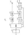
- FIG. 1 is a diagram illustrating a configuration example of a radar system according to the first embodiment of the present invention.
- the radar system 1 includes a central processing unit 10, radar devices 30 (30-1 to 30-3), a LAN (Local Area Network) 50, and a sensor group 60.
- the radar system 1 is mounted on a vehicle such as an automobile or a motorcycle, for example.
- the central processing unit 10 performs digital communication that synchronizes each operation to the radar device 30 (30-1 to 30-3) via the signal lines 40-1 to 40-3.
- the central processing unit 10 receives digital data transmitted from the radar device 30 (30-1 to 30-3) via the signal lines 40-1 to 40-3, and detects an object. Moreover, the presence or absence of danger is determined from the positional relationship between the detected object and the host vehicle, and the determination result is presented.
- the central processing unit 10 supplies power to the radar devices 30 (30-1 to 30-3).
- digital communication separated from the transmission / reception control in each radar device between the central processing unit 10 and the radar device 30 (30-1 to 30-3) For example, a signal line conforming to the LVDS (Low Voltage Differential Differential) specification can be used, but a signal line other than the signal line conforming to the LVDS specification should be used. Is also possible.
- LVDS Low Voltage Differential Differential
- the radar device 30 (30-1 to 30-3) transmits, for example, a high-frequency pulse signal, receives a reflected wave reflected by an object, and performs digital data (digital base) by A / D (Analog-to-Digital) conversion. Band signal), and then transmitted to the central processing unit 10.
- the LAN 50 is provided for exchanging information between the central processing unit 10 and other devices and systems.
- Examples of other devices and systems include a sensor group 60.
- CAN Controller Area Network
- the sensor group 60 has a plurality of sensors for detecting the state of the host vehicle.
- the sensor group 60 includes a vehicle speed sensor, a steering angle sensor, a yaw rate sensor, and the like. Of course, you may have sensors other than these.
- FIG. 2 is a block diagram showing a detailed configuration example of the central processing unit 10 shown in FIG.
- the central processing unit 10 includes I / Fs (Interfaces) 11-1 to 11-3, 18, a switch 12, a detection processing unit 13, an integration processing unit 14, and a risk determination processing unit 15.
- I / Fs Interfaces
- the I / Fs 11-1 to 11-3 are interfaces for transmitting and receiving digital data between the central processing unit 10 and the radar device 30 (30-1 to 30-3), respectively.
- the I / Fs 11-1 to 11-3 are set according to the specifications of the signal lines 40-1 to 40-3. In this embodiment, an interface conforming to the LVDS specification is used. It is also possible to use an interface.
- the switch 12 selects any of the I / Fs 11-1 to 11-3 according to the control of the command control unit 16, and supplies the data received by these to the detection processing unit 13.
- the detection processing unit 13 includes a presum processing unit 13a, a target detection processing unit 13b, and an angle detection processing unit 13c. For the data received from each of the radar devices 30 (30-1 to 30-3), Then, by executing the presum processing, the target detection processing, and the angle detection processing, the presence / absence, angle, etc. of the target (object) included in the data received from each radar apparatus is detected and supplied to the integration processing section 14 To do.
- the integration processing unit 14 includes a clustering processing unit 14a and a tracking processing unit 14b.
- the integration processing unit 14 performs integration processing on the information on the object in each radar device detected by the detection processing unit 13, thereby obtaining the information.
- the objects are integrated and specified and supplied to the danger determination processing unit 15.
- the danger determination processing unit 15 determines the presence or absence of danger based on the position information, speed information, angle information, and the like of the target object supplied from the integration processing unit 14 and the information on the host vehicle supplied from the sensor group 60. If it is determined as dangerous, the information indicating the danger is presented from, for example, the presentation unit 17 by notifying the command control unit 16.
- the command control unit 16 exchanges information with the radar apparatus 30 (30-1 to 30-3) via the I / Fs 11-1 to 11-3, and synchronizes their operation timings. Further, the command control unit 16 controls the switch 12 to select the radar device 30 (30-1 to 30-3) and receive data. Further, the command control unit 16 presents information indicating danger from the presentation unit 17 when the risk determination processing unit 15 determines that the risk is dangerous.
- the presentation unit 17 includes, for example, an LED (Light (Emitting Diode), a buzzer, or the like, and presents to the driver or the like that the host vehicle is in a dangerous state. Of course, you may comprise by devices (for example, liquid crystal display) other than LED and a buzzer.
- the command control unit 16 can also control the switch 12 so as to receive data from some radar devices.
- the I / F 18 receives information from the sensor group 60 via the LAN 50 shown in FIG. 1 and supplies information via the LAN 50 to an ECU (Electronic Control Unit) not shown.
- ECU Electronic Control Unit
- the I / F 18 is set according to the specifications of the LAN 50 and corresponds to CAN in this embodiment, but can also correspond to a network other than CAN.
- FIG. 3 is a diagram showing a configuration example of the radar apparatus 30 (30-1 to 30-3) shown in FIG. For simplicity of explanation, it is assumed that the radar apparatus 30 (30-1 to 30-3) has the same configuration. Hereinafter, these will be described as the radar device 30.
- the radar apparatus 30 includes an I / F 31, an individual control unit 32, a pulse generation unit 33, a transmission unit 34, a transmission antenna 35, reception antennas 36a and 36b, a switch 37, a reception unit 38, and ADC (Analog-to-Digital Converter) 39.
- I / F 31 an individual control unit 32, a pulse generation unit 33, a transmission unit 34, a transmission antenna 35, reception antennas 36a and 36b, a switch 37, a reception unit 38, and ADC (Analog-to-Digital Converter) 39.
- the I / F 31 is an interface for transmitting and receiving digital data between the radar device 30 (30-1 to 30-3) and the central processing unit 10.
- the I / F 31 is set according to the specifications of the signal lines 40-1 to 40-3 in the same manner as the I / Fs 11-1 to 11-3.
- an interface conforming to the LVDS specification is used.
- the individual control unit 32 controls the pulse generation unit 33 to transmit a high-frequency pulse signal toward the object, and supplies digital data supplied from the ADC 39 to the central processing unit 10 via the I / F 31. Further, the individual control unit 32 performs digital communication with the central processing unit 10 via the I / F 31 to synchronize the operation of the radar device 30 (30-1 to 30-3).
- the operation timing of the radar apparatus 30 (30-1 to 30-3) managed in the millisecond (ms) order and the transmission / reception timing of the high-frequency pulse signal managed in the nanosecond (ns) order for example. Both are controlled.
- the pulse generator 33 generates a pulse signal according to the control of the individual controller 32 and supplies the pulse signal to the transmitter 34.
- the transmission unit 34 up-converts the pulse signal supplied from the pulse generation unit 33 into a predetermined frequency band to form a high-frequency pulse signal, and transmits the high-frequency pulse signal toward the target via the transmission antenna 35. More specifically, the pulse generation unit 33 generates a baseband pulse signal having a pulse width of about 1 ns, for example, and the transmission unit 34 converts the pulse signal into, for example, a quasi-millimeter wave band or a millimeter wave band (specifically, Can be configured to radiate from the transmitting antenna 35 after being up-converted to 24 GHz to 28 GHz, 76 to 81 GHz, or the like. Of course, other frequencies may be used.
- the transmitting antenna 35 radiates the high-frequency signal supplied from the transmitting unit 34 to free space.
- the receiving antennas 36 a and 36 b are configured by arranging antennas having similar characteristics at a predetermined distance, receive a reflected wave reflected by an object, and supply the received wave to the switch 37.
- the switch 37 is controlled by the individual control unit 32, selects either the reception antenna 36a or the reception antenna 36b, and supplies the reception signal to the reception unit 38.
- the reception unit IQ demodulates the reception signal supplied from the switch 37 and outputs an I signal and a Q signal whose phases are orthogonal to each other.
- the ADC 39 is controlled by the individual control unit 32 and performs equivalent time sampling in which the I signal and the Q signal (analog signal) supplied from the reception unit 38 are sampled by shifting the sampling start timing by a predetermined time. The data is converted and supplied to the individual control unit 32. In addition, you may make it convert into digital data by normal sampling instead of equivalent time sampling.
- the output of the radar device 30 (30-1 to 30-3) is converted into digital data, and for example, the radar device 30 (30-1 to 30-3) managed in nanosecond (ns) order. Since the management of the time difference of transmission / reception of high-frequency signals and the pulse waveform is closed within the radar apparatus, for example, milliseconds (ms) as in the communication between the central processing unit 10 and the radar apparatus 30 (30-1 to 30-3). ) Separation from matters managed by order is ensured. There is also an advantage that the influence of changes in the usage environment of the central processing unit 10 and the radar device 30 (30-1 to 30-3) is reduced.
- the signals output from the receiving antennas 36a and 36b are selected by the switch 37.
- the signals output from the receiving antennas 36a and 36b are converted into sum signals by the hybrid circuit. It may be converted into a difference signal, and these sum signal and difference signal may be selected by the switch 37.
- FIG. 4 is a flowchart for explaining an example of processing executed in the central processing unit 10 shown in FIG. When the processing of this flowchart is started, the following steps are executed.
- step S10 the command control unit 16 instructs the radar device 30 (30-1 to 30-3) to transmit a high-frequency pulse signal at a predetermined timing.
- the radar apparatus 30 (30-1 to 30-3) transmits a high-frequency pulse signal at different timing (time division control), for example, as shown in FIG.
- the radar apparatus 30-1 transmits a high-frequency pulse signal with a period ⁇ .
- the period ⁇ is on the order of 0.1 ms to 10 ms
- the pulse width of the high frequency pulse signal is on the order of 0.1 ns to 10 ns.
- the radar apparatus 30-2 transmits the high-frequency pulse signal after the time ⁇ 2 has elapsed since the radar apparatus 30-1 transmitted the high-frequency pulse signal, and the radar apparatus 30-3 has the radar apparatus 30-1 transmit the pulse signal.
- the high frequency pulse signal is transmitted after the time ⁇ 3 has elapsed since the transmission. Thereby, it can prevent that the reflected wave from a target object interferes.
- step S11 the command control unit 16 receives data transmitted from the radar device 30 (30-1 to 30-3) via the signal lines 40-1 to 40-3. More specifically, in the radar apparatus 30 (30-1 to 30-3), the high-frequency pulse signal transmitted at the timing shown in FIG. 5 is captured by the receiving antennas 36a and 36b. Since the switch 37 is switched by the individual control unit 32 every time a high-frequency pulse signal is transmitted, the reflected wave captured by one of the receiving antennas 36a and 36b is input to the receiving unit 38. The reception unit 38 performs IQ demodulation on the reception signal supplied from the switch 37 and outputs an I signal and a Q signal whose phases are orthogonal to each other.
- the ADC 39 samples the I signal and the Q signal supplied from the receiving unit 38 based on a distance gate signal that is a gate signal indicating the distance from the radar apparatus, converts the signal into digital data, and supplies the digital data to the individual control unit 32. .
- the individual control unit 32 transmits digital data to the central processing unit 10 via the I / F 31.
- the command control unit 16 controls the switch 12, selects the corresponding one of the I / Fs 11-1 to 11-3, receives the digital data, and sends it to the detection processing unit 13. Supply.
- the detection processing unit 13 performs detection processing on the data received from each radar device. That is, the detection processing unit 13 executes time sharing (time division) processing, and executes data processing when reception of data from each radar apparatus is completed as shown in FIG. More specifically, the presum processing unit 13a adds and compresses a predetermined number of I and Q data which are data received by the same radar device and sampled in synchronization with the same distance gate. It is a presum value.
- the target detection processing unit 13b performs, for example, complex FFT processing on the presumed I and Q data with the I signal data as a real part and the Q signal data as an imaginary part, and each distance gate and frequency gate.
- the presence / absence of an object is detected by comparing each amplitude output corresponding to 1 with a preset threshold value. Further, the distance from the distance gate where the object is detected to the object is obtained, and the relative speed of the object is obtained from a frequency gate which is a gate for obtaining the speed.
- the angle detection processing unit 13c detects the angle between the object and the object based on a table indicating the relationship between the ratio of the imaginary part of the reception signals of the two reception antennas 36a and 36b and the angle, for example.
- step S13 the command control unit 16 determines whether or not data for one scan has been received. If it is determined that data for one scan has been received (step S13: Yes), the process proceeds to step S14. In other cases, the process returns to step S10 and the same processing is repeated.
- one scan refers to a period during which data for one time is sampled by equivalent time sampling. That is, in the equivalent time sampling, the reception signal for one pulse of the transmission signal is sampled at a constant time interval, and the timing at which sampling is started for each pulse is slightly shifted (by time ⁇ ). By performing this for a plurality of times of transmission of the pulse signal, a sampling result equivalent to sampling at the time interval ⁇ can be obtained.
- a pulse signal is output from the pulse generation unit 23 at 1 ms intervals, and this is performed continuously, for example, for 50 ms, it can be obtained by transmitting 50 pulse signals per scan. Equivalent time sampling is performed on the received signal. Note that the time interval for outputting the pulse signal and the number of times the pulse signal is output in one scan are not limited to those described above, and can be set as appropriate.
- step S14 the integration processing unit 14 integrates the data of the object received by each of the radar devices 30 (30-1 to 30-3) and detected by the detection processing unit 13, and converts the data into the integrated data.
- Clustering processing is executed for the included objects.
- the detection processing unit 13 executes a process for detecting a target for each data received by each of the radar devices 30 (30-1 to 30-3).
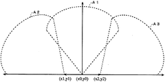
- the position where the radar apparatus 30 (30-1 to 30-3) is installed has a spatial shift. More specifically, as shown in FIG. 6, it is assumed that the detection range of the radar device 30-1 is A1, the detection range of the radar device 30-2 is A2, and the detection range of the radar device 30-3 is A3. The origins are different.
- the clustering processing unit 14a integrates the data into one coordinate system by adding the origin value as an offset value to the data of each radar device. If the data is expressed in a polar coordinate system, for example, after conversion to an orthogonal coordinate system, the value of the origin is added as an offset, or integration is performed by performing coordinate conversion in the polar coordinate system. Can do.
- the clustering processing unit 14a groups the data for one scan that has been integrated, and defines each group (cluster) as a set of data reflected by one object. In the grouping of detection signals, a region having a predetermined shape is set, and a set of signals in the region is processed as one cluster.
- cluster shape for example, a shape such as a circle, an ellipse, and a rectangle can be used. Note that if the detection ranges (A1 to A3) of the radar device 30 (30-1 to 30-3) are overlapped, it is possible to easily detect an object existing across the detection range as the same object. preferable.
- step S15 the tracking processing unit 14b performs a tracking process on the data that has been subjected to the clustering process in step S14. Specifically, the tracking processing unit 14b determines which object the cluster group obtained by the clustering process is compared with the position of each object obtained so far. In addition, the position of each object is smoothed (averaged) and the position is predicted at the next timing.
- the ⁇ - ⁇ filtering method and the Kalman filter method can be used for smoothing and predicting the position in the tracking process.
- step S16 the danger determination processing unit 15 obtains the position, speed, and angle of the target obtained by the tracking process in step S15, and the position, speed, and the own vehicle obtained from the sensor group 60. Based on the rudder angle, it is determined whether or not there is a possibility that the target object touches or collides with the host vehicle. 16 is notified. Thereby, information indicating that the danger is approaching the presentation unit 17 is presented.
- step S17 the command control unit 16 determines whether or not to continue the process. If the process is to be continued (step S17: Yes), the process returns to step S10 and repeats the same process as described above. Otherwise (step S17: No), the process ends.
- the radar device 30 (30-1 to 30-3) transmits / receives a high-frequency pulse signal, converts it to digital data, and transmits it to the central processing unit 10.
- the object detection process and the integration process are executed.
- each of the radar devices 30 (30-1 to 30-3) independently manages the transmission timing and reception timing of the high-frequency pulse signal, for example, on the nanosecond (ns) order
- the processing device 10 may manage the synchronization of the operations of the radar devices 30 (30-1 to 30-3) on the order of milliseconds (ms), for example, and the central processing device 10 may control each synchronization on the order of nanoseconds (ns), for example. It is not necessary to manage the transmission / reception timing of the radar apparatus 30 (30-1 to 30-3). Therefore, the processing load on the central processing unit 10 can be reduced, and the radar apparatus 30 (30-1 to 30-3) can transmit and receive pulses at an appropriate timing.
- the processing amount of each radar device 30 (30-1 to 30-3) is reduced, the unit price of the radar device 30 (30-1 to 30-3) is reduced.
- the cost of the entire system can be reduced.
- the central processing unit 10 executes the detection process in a time-sharing manner, the detection processing unit 13 can be shared, so that the cost of the central processing unit 10 can be reduced. it can. Further, since the radar device 30 (30-1 to 30-3) transmits the high-frequency pulse signal at different timings, it is possible to prevent the transmission wave and the reflected wave from interfering between the radar devices.
- the integration processing unit 14 integrates the data detected by the radar apparatus 30 (30-1 to 30-3) and executes the clustering process and tracking process. An object existing across the detection ranges A1 to A3 of the radar apparatus 30 (30-1 to 30-3) can be reliably detected.
- the high frequency pulse signal is transmitted in a time division manner as shown in FIG. 5, but for example, as shown in FIG. 7, the high frequency pulse signal is transmitted at substantially the same timing.
- the data obtained by the ADC 39 may be transmitted to the central processing unit 10 with the time adjusted. More specifically, in the example shown in FIG. 7, the radar device 30 (30-1 to 30-3) transmits a high-frequency pulse signal at substantially the same timing, is converted into digital data by the ADC 39, and is stored in a memory (not shown). .
- the central processing unit 10 requests data transmission in a predetermined order, for example, in the order of the radar devices 30 (30-1 to 30-3), receives the transmitted data, and detects as described above. It is also possible to execute processing and integration processing.
- the central processing unit 10 does not manage the timing of data transmission from the radar device 30 (30-1 to 30-3), for example, in response to a request from the radar device 30 (30-1 to 30-3). Based on this, the central processing unit 10 may execute bus arbitration (bus arbitration), for example, and assign usage rights in the order of arrival.
- bus arbitration bus arbitration
- FIGS. 8 and 9 are diagrams showing a configuration example of the second embodiment of the present invention.
- portions corresponding to those in FIGS. 2 and 3 are denoted by the same reference numerals and description thereof is omitted.
- the central processing unit 10 shown in FIG. 8 compared with FIG. 2, the presum processing unit 13a and the target detection processing unit 13b of the detection processing unit 13 are excluded.
- Other configurations are the same as those in FIG.
- a detection processing unit 113 is provided between the ADC 39 and the control unit as compared with FIG. Other configurations are the same as those in FIG.
- the detection processing unit 113 includes a presum processing unit 113 a and a target detection processing unit 113 b, which performs presum processing and target processing on the digital data supplied from the ADC 39 and outputs it to the individual control unit 32.
- the presum processing unit 113a and the target detection processing unit 113b have the same functions as the presum processing unit 13a and the target detection processing unit 13b shown in FIG. That is, in the second embodiment shown in FIGS.
- the presum processing unit 13a and the target detection processing unit 13b are excluded from the central processing unit 10 shown in FIG. 3, and the radar device 30 (30-1 to 30-3) is replaced.
- a presum processing unit 113a and a target detection processing unit 113b are added.
- the radar device 30 when a request is made from the central processing unit 10, the radar device 30 (30-1 to 30-3) performs the timing shown in FIG. A high frequency pulse signal is transmitted at the timing shown in FIG.
- the reflected waves received by the receiving units 38 of the radar apparatus 30 (30-1 to 30-3) are converted into digital data by the ADC 39 and supplied to the detection processing unit 113.
- the detection processing unit 113 the presum processing is executed in the presum processing unit 113a, and the target is detected in the target detection processing unit 113b, and then supplied to the individual control unit 32.
- the individual control unit 32 transmits information regarding the detected target to the central processing unit 10 via the I / F 31.
- the switch 12 selects the I / Fs 11-1 to 11-3, and receives data (data after target detection processing) transmitted from the radar device 30 (30-1 to 30-3).
- the angle detection processing unit 13 c executes processing for detecting the angle of the target detected in each of the radar devices 30 (30-1 to 30-3) and supplies it to the integration processing unit 14.
- the integration processing unit 14 as in the case of the first embodiment described above, information on the targets detected by each of the radar devices 30 (30-1 to 30-3) supplied from the detection processing unit 13 is integrated.
- the clustering processing unit 14a integrates the coordinate systems of the data related to the targets detected in each of the radar devices 30 (30-1 to 30-3) and executes a clustering process.
- the tracking processing unit 14 b performs tracking processing on the data on which clustering processing has been performed, and outputs the tracking processing to the risk determination processing unit 15.
- the danger determination processing unit 15 determines the presence / absence of danger based on the data output from the integration processing unit 14 and the data from the sensor group 60.
- the presentation unit 17 presents predetermined information.
- a part of the detection processing is executed in each of the radar devices 30 (30-1 to 30-3).
- 30-1 to 30-3) can reduce the amount of data transmitted to the central processing unit 10, so that the interface between the radar device 30 (30-1 to 30-3) and the central processing unit 10 can be It becomes possible to use a low-speed interface.
- the data executed up to the target detection process has a considerably reduced data amount, so that the required transmission rate of the interface can be reduced as compared with the first embodiment.
- the present invention is not limited to the case as described above.
- the presum is provided in the radar device 30 (30-1 to 30-3).
- the processing unit 113a and the target detection processing unit 113b are moved and arranged, for example, one or more of the presum processing unit 13a, the target detection processing unit 13b, and the angle detection processing unit 13c may be moved and arranged. Good. However, it is not preferable to move and arrange all of these because the power consumption of the radar apparatus 30 (30-1 to 30-3) cannot be reduced.
- the presum processing unit 13a, the target detection processing unit 13b, and the angle detection processing unit 13c are arranged in the central processing unit 10 or the radar device 30 (30-1 to 30-3) depends on the cost of the device, the interface Can be determined according to the transmission speed of the system, the power consumption of the entire system, and the like.
- the detection process of the detection processing unit is assumed to be a presum process, a target process, and an angle detection process, but other processes may be included.
- the detection process may include a relative speed detection process, a position detection process, and the like. Of course, processes other than these processes may be included.
- one detection processing unit 13 is provided to process data from the radar apparatus 30 (30-1 to 30-3) by time division processing.
- the detection processing unit 13 may be provided in the same number as the radar apparatus and processed in parallel. In that case, the switch 12 becomes unnecessary. It is also possible to perform time-sharing processing on only a part of the detection processing unit 13. For example, only the presum processing, or both the presum processing and the target processing may be time-division processed. According to such a configuration, it is possible to improve the processing speed with the cost being suppressed as much as possible by parallelizing only the processing with a large load.
- the radar apparatus 30 (30-1 to 30-3) has the same configuration. For example, there is a difference in performance (for example, processing speed or target resolution) depending on the installation position.
- performance for example, processing speed or target resolution
- time-sharing processing it is possible to allocate a long time to a high-performance radar device. For example, when three radar devices 30 (30-1 to 30-3) are arranged at the rear part of the vehicle and arranged at the rear center and the rear left and right, the performance of the radar device arranged at the rear center. Can be high.
- three radar devices are provided, but two of these may be provided, or four or more may be provided. Further, a short-range radar, a medium-range radar, and a long-range radar may be provided in appropriate combination.
- the radar system 1 is mounted on a vehicle has been described as an example.
- the radar system 1 may be mounted on another moving body such as an aircraft or a ship.
Landscapes
- Engineering & Computer Science (AREA)
- Radar, Positioning & Navigation (AREA)
- Remote Sensing (AREA)
- Physics & Mathematics (AREA)
- Computer Networks & Wireless Communication (AREA)
- General Physics & Mathematics (AREA)
- Electromagnetism (AREA)
- Radar Systems Or Details Thereof (AREA)
Abstract
L'invention concerne un système radar possédant une pluralité de dispositifs radars (30) et un dispositif de traitement central (10), chaque dispositif radar possédant au moins un moyen de transmission pour transmettre un signal haute fréquence à un objet, un moyen de réception pour recevoir le signal réfléchi par l'objet, un moyen de commande pour commander la synchronisation de la transmission et de la réception par le moyen de transmission et le moyen de réception, et un moyen de conversion pour convertir le signal reçu par le moyen de réception en données numériques ; le dispositif de traitement central possède un moyen de traitement d'intégration pour associer les informations transmises de la pluralité de dispositifs radars à des informations de position pour la pluralité de dispositifs radars et traiter les informations transmises et un moyen de traitement de détection pour effectuer, sur les données numériques non encore traitées par le moyen de traitement d'intégration, un traitement pour détecter l'objet ; la communication numérique entre la pluralité de dispositifs radars et le dispositif de traitement central est effectuée séparément de la commande de synchronisation de transmission et réception par chacun des moyens de commande individuels de la pluralité de dispositifs radars ; et la gestion des différences de temps entre la transmission et la réception des signaux haute fréquence de la pluralité de dispositifs radars peut être exécutée de sorte que l'effet des fluctuations d'environnement d'utilisation est réduit.
Priority Applications (5)
| Application Number | Priority Date | Filing Date | Title |
|---|---|---|---|
| JP2014543032A JP5916878B2 (ja) | 2013-05-01 | 2013-05-01 | レーダシステム |
| CN201380076190.9A CN105247385B (zh) | 2013-05-01 | 2013-05-01 | 雷达系统 |
| PCT/JP2013/062709 WO2014178131A1 (fr) | 2013-05-01 | 2013-05-01 | Système radar |
| EP13883795.0A EP2993488B1 (fr) | 2013-05-01 | 2013-05-01 | Système radar |
| US14/926,142 US10247819B2 (en) | 2013-05-01 | 2015-10-29 | Radar system |
Applications Claiming Priority (1)
| Application Number | Priority Date | Filing Date | Title |
|---|---|---|---|
| PCT/JP2013/062709 WO2014178131A1 (fr) | 2013-05-01 | 2013-05-01 | Système radar |
Related Child Applications (1)
| Application Number | Title | Priority Date | Filing Date |
|---|---|---|---|
| US14/926,142 Continuation US10247819B2 (en) | 2013-05-01 | 2015-10-29 | Radar system |
Publications (1)
| Publication Number | Publication Date |
|---|---|
| WO2014178131A1 true WO2014178131A1 (fr) | 2014-11-06 |
Family
ID=51843282
Family Applications (1)
| Application Number | Title | Priority Date | Filing Date |
|---|---|---|---|
| PCT/JP2013/062709 Ceased WO2014178131A1 (fr) | 2013-05-01 | 2013-05-01 | Système radar |
Country Status (5)
| Country | Link |
|---|---|
| US (1) | US10247819B2 (fr) |
| EP (1) | EP2993488B1 (fr) |
| JP (1) | JP5916878B2 (fr) |
| CN (1) | CN105247385B (fr) |
| WO (1) | WO2014178131A1 (fr) |
Cited By (7)
| Publication number | Priority date | Publication date | Assignee | Title |
|---|---|---|---|---|
| JP2017142228A (ja) * | 2015-12-10 | 2017-08-17 | ローベルト ボッシュ ゲゼルシャフト ミット ベシュレンクテル ハフツング | 自動車用のレーダ装置を運転するための方法 |
| JP2018503833A (ja) * | 2014-11-26 | 2018-02-08 | マリタイム レーダー システムズ リミテッド | 海洋環境を監視するためのシステム |
| JP2018100944A (ja) * | 2016-12-21 | 2018-06-28 | 川崎地質株式会社 | チャープ式マルチ地中レーダシステム |
| JP2018119934A (ja) * | 2017-01-27 | 2018-08-02 | 古河電気工業株式会社 | レーダ装置、レーダ装置の制御方法、および、レーダシステム |
| JP2021518540A (ja) * | 2018-03-22 | 2021-08-02 | ロベルト・ボッシュ・ゲゼルシャフト・ミト・ベシュレンクテル・ハフツングRobert Bosch Gmbh | レーダシステム用レーダセンサヘッド |
| JPWO2021171638A1 (fr) * | 2020-02-25 | 2021-09-02 | ||
| JPWO2022149589A1 (fr) * | 2021-01-07 | 2022-07-14 |
Families Citing this family (17)
| Publication number | Priority date | Publication date | Assignee | Title |
|---|---|---|---|---|
| JP3057983B2 (ja) | 1993-11-30 | 2000-07-04 | 東京都 | ベルトプレス型脱水機の制御装置 |
| EP3299843A1 (fr) * | 2016-09-23 | 2018-03-28 | MediaTek Inc. | Procédé et appareil d'aide au stationnement pour automobile à l'aide de capteurs radar |
| US9736845B1 (en) * | 2017-01-03 | 2017-08-15 | Network Performance Research Group Llc | Over the air signaling of dynamic frequency selection (DFS) operating parameters to client devices |
| CN107329145B (zh) * | 2017-06-29 | 2024-04-12 | 深圳市速腾聚创科技有限公司 | 多激光雷达系统及其控制方法 |
| CN107272017A (zh) * | 2017-06-29 | 2017-10-20 | 深圳市速腾聚创科技有限公司 | 多激光雷达系统及其控制方法 |
| EP3435113B1 (fr) * | 2017-07-23 | 2021-11-03 | NXP USA, Inc. | Procédé de détection d'un objet |
| DE102018216538A1 (de) * | 2018-09-27 | 2020-04-02 | Robert Bosch Gmbh | Radarsensor mit synchronisierten Hochfrequenzbausteinen |
| CN109283520A (zh) * | 2018-10-19 | 2019-01-29 | 芜湖易来达雷达科技有限公司 | Adas系统中多雷达协作装置及其协作方法 |
| DE102018220011A1 (de) * | 2018-11-22 | 2020-05-28 | Robert Bosch Gmbh | Sensorsystem für ein Fahrzeug und Verfahren zum Betreiben eines Sensorsystems für ein Fahrzeug |
| US12246677B2 (en) * | 2019-07-17 | 2025-03-11 | Vitesco Technologies GmbH | Method for opening an opening panel of a motor vehicle by motion detection, using a doppler radar, and associated detection device |
| DE102020102380B4 (de) | 2020-01-31 | 2025-06-26 | Audi Aktiengesellschaft | Verfahren zum Betrieb einer mehrere Radarsensoren umfassenden Radareinrichtung und Kraftfahrzeug |
| EP4103966A4 (fr) | 2020-02-10 | 2024-04-17 | Perceptive Inc. | Système centralisé de réseau de capteurs de détection d'objet |
| DE102020211745A1 (de) * | 2020-09-21 | 2022-03-24 | Robert Bosch Gesellschaft mit beschränkter Haftung | Verfahren zur Auswertung von Radarsignalen in einem Radarsystem mit mehreren Sensoreinheiten |
| TWI746316B (zh) * | 2020-12-16 | 2021-11-11 | 技嘉科技股份有限公司 | 主動式測距裝置以及主動式測距方法 |
| FI130773B1 (fi) * | 2021-01-05 | 2024-03-11 | Teknologian Tutkimuskeskus Vtt Oy | Verkkosolmu jätteenhallintajärjestelmään |
| US11982734B2 (en) * | 2021-01-06 | 2024-05-14 | Lassen Peak, Inc. | Systems and methods for multi-unit collaboration for noninvasive detection of concealed impermissible objects |
| WO2024026771A1 (fr) * | 2022-08-04 | 2024-02-08 | Oppo广东移动通信有限公司 | Procédé et dispositif d'authentification d'accès |
Citations (11)
| Publication number | Priority date | Publication date | Assignee | Title |
|---|---|---|---|---|
| JPH0551870B2 (fr) | 1988-06-06 | 1993-08-03 | Boeicho Gijutsu Kenkyu Honbuch | |
| JPH08105963A (ja) * | 1994-10-06 | 1996-04-23 | Hitachi Ltd | レーダ装置 |
| JP2002372577A (ja) * | 2001-06-14 | 2002-12-26 | Matsushita Electric Works Ltd | 障害物検出装置 |
| JP2003107151A (ja) | 2001-10-01 | 2003-04-09 | Mitsubishi Electric Corp | 覆域統制装置およびセンサ装置 |
| JP2005077302A (ja) * | 2003-09-02 | 2005-03-24 | Fujitsu Ten Ltd | 物体検出装置 |
| JP2006125947A (ja) * | 2004-10-27 | 2006-05-18 | Tdk Corp | レーダー装置 |
| JP2007033156A (ja) * | 2005-07-25 | 2007-02-08 | Secom Co Ltd | レーダ装置 |
| JP2007232498A (ja) * | 2006-02-28 | 2007-09-13 | Hitachi Ltd | 障害物検知システム |
| JP2008039616A (ja) * | 2006-08-07 | 2008-02-21 | Fujitsu Ltd | 広帯域レーダ装置及びその移動物体検出方法 |
| JP2008152391A (ja) * | 2006-12-14 | 2008-07-03 | Toyota Motor Corp | 車両用周辺監視装置 |
| JP2009294930A (ja) * | 2008-06-05 | 2009-12-17 | Toyota Motor Corp | 障害物検出装置および障害物検出システム |
Family Cites Families (15)
| Publication number | Priority date | Publication date | Assignee | Title |
|---|---|---|---|---|
| US5087918A (en) * | 1990-04-02 | 1992-02-11 | Delco Electronics Corporation | FMCW/2FD implementation for vehicle near obstacle detection system |
| JPH08166448A (ja) * | 1994-12-13 | 1996-06-25 | Honda Motor Co Ltd | 車両用周囲監視装置 |
| US5767793A (en) * | 1995-04-21 | 1998-06-16 | Trw Inc. | Compact vehicle based rear and side obstacle detection system including multiple antennae |
| JP2003016592A (ja) * | 2001-06-27 | 2003-01-17 | Yoshio Shimotori | 車輌運転における警告装置 |
| US7719994B2 (en) * | 2006-04-26 | 2010-05-18 | Honeywell International Inc. | Sub-frame synchronized ranging |
| JP5027120B2 (ja) | 2006-06-01 | 2012-09-19 | 古河電気工業株式会社 | バースト発振装置、バースト発振方法及び測距通信システム |
| JP2008003779A (ja) * | 2006-06-21 | 2008-01-10 | Hitachi Ltd | 予防安全自動車の計測データ処理装置 |
| US7492313B1 (en) * | 2006-10-31 | 2009-02-17 | Lockheed Martin Corporation | Digital processing radar system |
| DE102007054821A1 (de) * | 2007-11-16 | 2009-05-20 | Robert Bosch Gmbh | Verfahren zur Schätzung der Breite von Radarobjekten |
| US7737880B2 (en) * | 2008-10-22 | 2010-06-15 | Honeywell International Inc. | Microwave and millimeterwave radar sensors |
| CN102301405B (zh) * | 2009-01-29 | 2014-01-15 | 丰田自动车株式会社 | 物体识别装置以及物体识别方法 |
| JP4976442B2 (ja) * | 2009-03-27 | 2012-07-18 | 古河電気工業株式会社 | モノパルスドップラレーダ装置 |
| JP2010175555A (ja) * | 2010-03-26 | 2010-08-12 | Furukawa Electric Co Ltd:The | パルスドップラレーダ装置 |
| EP2495634B1 (fr) | 2011-03-01 | 2015-08-26 | Siemens Aktiengesellschaft | Générateur à base de temps et procédé de fourniture d'un premier signal d'horloge et d'un deuxième signal d'horloge |
| DE102011075552A1 (de) * | 2011-05-10 | 2012-11-15 | Robert Bosch Gmbh | Schaltungsanordnung für Radaranwendungen |
-
2013
- 2013-05-01 WO PCT/JP2013/062709 patent/WO2014178131A1/fr not_active Ceased
- 2013-05-01 JP JP2014543032A patent/JP5916878B2/ja active Active
- 2013-05-01 EP EP13883795.0A patent/EP2993488B1/fr active Active
- 2013-05-01 CN CN201380076190.9A patent/CN105247385B/zh active Active
-
2015
- 2015-10-29 US US14/926,142 patent/US10247819B2/en not_active Expired - Fee Related
Patent Citations (11)
| Publication number | Priority date | Publication date | Assignee | Title |
|---|---|---|---|---|
| JPH0551870B2 (fr) | 1988-06-06 | 1993-08-03 | Boeicho Gijutsu Kenkyu Honbuch | |
| JPH08105963A (ja) * | 1994-10-06 | 1996-04-23 | Hitachi Ltd | レーダ装置 |
| JP2002372577A (ja) * | 2001-06-14 | 2002-12-26 | Matsushita Electric Works Ltd | 障害物検出装置 |
| JP2003107151A (ja) | 2001-10-01 | 2003-04-09 | Mitsubishi Electric Corp | 覆域統制装置およびセンサ装置 |
| JP2005077302A (ja) * | 2003-09-02 | 2005-03-24 | Fujitsu Ten Ltd | 物体検出装置 |
| JP2006125947A (ja) * | 2004-10-27 | 2006-05-18 | Tdk Corp | レーダー装置 |
| JP2007033156A (ja) * | 2005-07-25 | 2007-02-08 | Secom Co Ltd | レーダ装置 |
| JP2007232498A (ja) * | 2006-02-28 | 2007-09-13 | Hitachi Ltd | 障害物検知システム |
| JP2008039616A (ja) * | 2006-08-07 | 2008-02-21 | Fujitsu Ltd | 広帯域レーダ装置及びその移動物体検出方法 |
| JP2008152391A (ja) * | 2006-12-14 | 2008-07-03 | Toyota Motor Corp | 車両用周辺監視装置 |
| JP2009294930A (ja) * | 2008-06-05 | 2009-12-17 | Toyota Motor Corp | 障害物検出装置および障害物検出システム |
Non-Patent Citations (2)
| Title |
|---|
| H.-L. BLOECHER ET AL.: "79GHz UWB automotive short range radar-Spectrum allocation and technology trends", ADV. RADIO SCI., vol. 7, 2009, pages 61 - 65, XP055318938, DOI: doi:10.5194/ars-7-61-2009 |
| See also references of EP2993488A4 |
Cited By (14)
| Publication number | Priority date | Publication date | Assignee | Title |
|---|---|---|---|---|
| JP2018503833A (ja) * | 2014-11-26 | 2018-02-08 | マリタイム レーダー システムズ リミテッド | 海洋環境を監視するためのシステム |
| JP2017142228A (ja) * | 2015-12-10 | 2017-08-17 | ローベルト ボッシュ ゲゼルシャフト ミット ベシュレンクテル ハフツング | 自動車用のレーダ装置を運転するための方法 |
| JP2018100944A (ja) * | 2016-12-21 | 2018-06-28 | 川崎地質株式会社 | チャープ式マルチ地中レーダシステム |
| JP7112829B2 (ja) | 2017-01-27 | 2022-08-04 | 古河電気工業株式会社 | レーダ装置、レーダ装置の制御方法、および、レーダシステム |
| JP2018119934A (ja) * | 2017-01-27 | 2018-08-02 | 古河電気工業株式会社 | レーダ装置、レーダ装置の制御方法、および、レーダシステム |
| JP2021518540A (ja) * | 2018-03-22 | 2021-08-02 | ロベルト・ボッシュ・ゲゼルシャフト・ミト・ベシュレンクテル・ハフツングRobert Bosch Gmbh | レーダシステム用レーダセンサヘッド |
| JP7008838B2 (ja) | 2018-03-22 | 2022-01-25 | ロベルト・ボッシュ・ゲゼルシャフト・ミト・ベシュレンクテル・ハフツング | レーダシステム用レーダセンサヘッド |
| US11536802B2 (en) | 2018-03-22 | 2022-12-27 | Robert Bosch Gmbh | Radar sensor head for a radar system |
| JPWO2021171638A1 (fr) * | 2020-02-25 | 2021-09-02 | ||
| WO2021171638A1 (fr) * | 2020-02-25 | 2021-09-02 | 古河電気工業株式会社 | Dispositif de traitement, procédé de traitement et programme de traitement |
| JP7383004B2 (ja) | 2020-02-25 | 2023-11-17 | 古河電気工業株式会社 | レーダシステム、処理方法および処理プログラム |
| US12189023B2 (en) | 2020-02-25 | 2025-01-07 | Furukawa Electric Co., Ltd. | Radar system, processing method, and processing program |
| JPWO2022149589A1 (fr) * | 2021-01-07 | 2022-07-14 | ||
| JP7763786B2 (ja) | 2021-01-07 | 2025-11-04 | パナソニック インテレクチュアル プロパティ コーポレーション オブ アメリカ | 三次元データ復号方法、三次元データ符号化方法、三次元データ復号装置、及び三次元データ符号化装置 |
Also Published As
| Publication number | Publication date |
|---|---|
| EP2993488A4 (fr) | 2016-12-21 |
| US20160109568A1 (en) | 2016-04-21 |
| CN105247385A (zh) | 2016-01-13 |
| EP2993488A1 (fr) | 2016-03-09 |
| CN105247385B (zh) | 2017-08-25 |
| EP2993488B1 (fr) | 2022-01-12 |
| US10247819B2 (en) | 2019-04-02 |
| JPWO2014178131A1 (ja) | 2017-02-23 |
| JP5916878B2 (ja) | 2016-05-11 |
Similar Documents
| Publication | Publication Date | Title |
|---|---|---|
| JP5916878B2 (ja) | レーダシステム | |
| CN105842700B (zh) | 车辆雷达系统及控制其的方法 | |
| CN110100188B (zh) | 针对扩展雷达系统的时间和频率同步 | |
| US8717224B2 (en) | Integrated radar apparatus and intergrated antenna apparatus | |
| Tokoro et al. | Electronically scanned millimeter-wave radar for pre-crash safety and adaptive cruise control system | |
| EP3964853B1 (fr) | Système et procédé d'estimation et compensation de dérive d'oscillateur local dans des capteurs en cascade | |
| JP2015152335A (ja) | レーダ装置、車両制御システム、および、信号処理方法 | |
| WO2014147980A1 (fr) | Dispositif radar | |
| WO2018102806A1 (fr) | Synchronisation de dispositifs de véhicule sur un réseau local de commande | |
| JP2015042962A (ja) | アンテナ、レーダ装置、および、信号処理方法 | |
| JP2013160585A (ja) | レーダ装置とその制御方法 | |
| US20180284267A1 (en) | A modular vehicle radar | |
| EP3859388A1 (fr) | Dispositif électronique, procédé de commande de dispositif électronique et programme de commande de dispositif électronique | |
| US12189023B2 (en) | Radar system, processing method, and processing program | |
| JP2007187632A (ja) | レーダー装置 | |
| KR20140083709A (ko) | 레이더 장치 및 이에 적용되는 신호처리방법 | |
| JP2022093367A (ja) | 情報測定方法および情報測定装置 | |
| WO2018000666A1 (fr) | Système radar, véhicule de transport, véhicule aérien sans pilote et procédé de détection | |
| KR100982697B1 (ko) | 레이더 펄스의 송신 타이밍 동기화를 이용한 간섭 억제 장치 및 방법과, 상기 방법을 행하는 프로그램을 기록한 컴퓨터로 읽을 수 있는 매체, 그리고 상기 장치를 이용한 차량 레이더 시스템 | |
| EP4202473A1 (fr) | Chaîne de traitement de capteur radar | |
| JP2022105870A (ja) | レーダシステム、処理方法および処理プログラム | |
| JP2010204031A (ja) | 車両用レーダ装置 | |
| JP2013221838A (ja) | レーダ制御装置 | |
| US20250189622A1 (en) | Radar system | |
| US20250206251A1 (en) | Collision mode prediction device and occupant protectant system |
Legal Events
| Date | Code | Title | Description |
|---|---|---|---|
| ENP | Entry into the national phase |
Ref document number: 2014543032 Country of ref document: JP Kind code of ref document: A |
|
| 121 | Ep: the epo has been informed by wipo that ep was designated in this application |
Ref document number: 13883795 Country of ref document: EP Kind code of ref document: A1 |
|
| NENP | Non-entry into the national phase |
Ref country code: DE |
|
| WWE | Wipo information: entry into national phase |
Ref document number: 2013883795 Country of ref document: EP |