EP2180962B1 - Verfahren und anlage zur gewinnung von metallteilen aus rückständen von müllverbrennungsprozessen - Google Patents
Verfahren und anlage zur gewinnung von metallteilen aus rückständen von müllverbrennungsprozessen Download PDFInfo
- Publication number
- EP2180962B1 EP2180962B1 EP20080785684 EP08785684A EP2180962B1 EP 2180962 B1 EP2180962 B1 EP 2180962B1 EP 20080785684 EP20080785684 EP 20080785684 EP 08785684 A EP08785684 A EP 08785684A EP 2180962 B1 EP2180962 B1 EP 2180962B1
- Authority
- EP
- European Patent Office
- Prior art keywords
- metal
- slag
- rotor elements
- metals
- shaft
- Prior art date
- Legal status (The legal status is an assumption and is not a legal conclusion. Google has not performed a legal analysis and makes no representation as to the accuracy of the status listed.)
- Active
Links
Images
Classifications
-
- B—PERFORMING OPERATIONS; TRANSPORTING
- B03—SEPARATION OF SOLID MATERIALS USING LIQUIDS OR USING PNEUMATIC TABLES OR JIGS; MAGNETIC OR ELECTROSTATIC SEPARATION OF SOLID MATERIALS FROM SOLID MATERIALS OR FLUIDS; SEPARATION BY HIGH-VOLTAGE ELECTRIC FIELDS
- B03B—SEPARATING SOLID MATERIALS USING LIQUIDS OR USING PNEUMATIC TABLES OR JIGS
- B03B9/00—General arrangement of separating plant, e.g. flow sheets
- B03B9/04—General arrangement of separating plant, e.g. flow sheets specially adapted for furnace residues, smeltings, or foundry slags
-
- B—PERFORMING OPERATIONS; TRANSPORTING
- B02—CRUSHING, PULVERISING, OR DISINTEGRATING; PREPARATORY TREATMENT OF GRAIN FOR MILLING
- B02C—CRUSHING, PULVERISING, OR DISINTEGRATING IN GENERAL; MILLING GRAIN
- B02C13/00—Disintegrating by mills having rotary beater elements ; Hammer mills
- B02C13/14—Disintegrating by mills having rotary beater elements ; Hammer mills with vertical rotor shaft, e.g. combined with sifting devices
- B02C13/16—Disintegrating by mills having rotary beater elements ; Hammer mills with vertical rotor shaft, e.g. combined with sifting devices with beaters hinged to the rotor
-
- B—PERFORMING OPERATIONS; TRANSPORTING
- B02—CRUSHING, PULVERISING, OR DISINTEGRATING; PREPARATORY TREATMENT OF GRAIN FOR MILLING
- B02C—CRUSHING, PULVERISING, OR DISINTEGRATING IN GENERAL; MILLING GRAIN
- B02C13/00—Disintegrating by mills having rotary beater elements ; Hammer mills
- B02C13/26—Details
- B02C13/28—Shape or construction of beater elements
-
- C—CHEMISTRY; METALLURGY
- C22—METALLURGY; FERROUS OR NON-FERROUS ALLOYS; TREATMENT OF ALLOYS OR NON-FERROUS METALS
- C22B—PRODUCTION AND REFINING OF METALS; PRETREATMENT OF RAW MATERIALS
- C22B7/00—Working up raw materials other than ores, e.g. scrap, to produce non-ferrous metals and compounds thereof; Methods of a general interest or applied to the winning of more than two metals
- C22B7/005—Separation by a physical processing technique only, e.g. by mechanical breaking
-
- C—CHEMISTRY; METALLURGY
- C22—METALLURGY; FERROUS OR NON-FERROUS ALLOYS; TREATMENT OF ALLOYS OR NON-FERROUS METALS
- C22B—PRODUCTION AND REFINING OF METALS; PRETREATMENT OF RAW MATERIALS
- C22B7/00—Working up raw materials other than ores, e.g. scrap, to produce non-ferrous metals and compounds thereof; Methods of a general interest or applied to the winning of more than two metals
- C22B7/04—Working-up slag
-
- F—MECHANICAL ENGINEERING; LIGHTING; HEATING; WEAPONS; BLASTING
- F23—COMBUSTION APPARATUS; COMBUSTION PROCESSES
- F23J—REMOVAL OR TREATMENT OF COMBUSTION PRODUCTS OR COMBUSTION RESIDUES; FLUES
- F23J1/00—Removing ash, clinker, or slag from combustion chambers
-
- B—PERFORMING OPERATIONS; TRANSPORTING
- B02—CRUSHING, PULVERISING, OR DISINTEGRATING; PREPARATORY TREATMENT OF GRAIN FOR MILLING
- B02C—CRUSHING, PULVERISING, OR DISINTEGRATING IN GENERAL; MILLING GRAIN
- B02C13/00—Disintegrating by mills having rotary beater elements ; Hammer mills
- B02C13/26—Details
- B02C13/28—Shape or construction of beater elements
- B02C2013/2816—Shape or construction of beater elements of chain, rope or cable type
-
- F—MECHANICAL ENGINEERING; LIGHTING; HEATING; WEAPONS; BLASTING
- F23—COMBUSTION APPARATUS; COMBUSTION PROCESSES
- F23J—REMOVAL OR TREATMENT OF COMBUSTION PRODUCTS OR COMBUSTION RESIDUES; FLUES
- F23J2900/00—Special arrangements for conducting or purifying combustion fumes; Treatment of fumes or ashes
- F23J2900/01001—Sorting and classifying ashes or fly-ashes from the combustion chamber before further treatment
-
- F—MECHANICAL ENGINEERING; LIGHTING; HEATING; WEAPONS; BLASTING
- F23—COMBUSTION APPARATUS; COMBUSTION PROCESSES
- F23J—REMOVAL OR TREATMENT OF COMBUSTION PRODUCTS OR COMBUSTION RESIDUES; FLUES
- F23J2900/00—Special arrangements for conducting or purifying combustion fumes; Treatment of fumes or ashes
- F23J2900/01003—Ash crushing means associated with ash removal means
-
- Y—GENERAL TAGGING OF NEW TECHNOLOGICAL DEVELOPMENTS; GENERAL TAGGING OF CROSS-SECTIONAL TECHNOLOGIES SPANNING OVER SEVERAL SECTIONS OF THE IPC; TECHNICAL SUBJECTS COVERED BY FORMER USPC CROSS-REFERENCE ART COLLECTIONS [XRACs] AND DIGESTS
- Y02—TECHNOLOGIES OR APPLICATIONS FOR MITIGATION OR ADAPTATION AGAINST CLIMATE CHANGE
- Y02P—CLIMATE CHANGE MITIGATION TECHNOLOGIES IN THE PRODUCTION OR PROCESSING OF GOODS
- Y02P10/00—Technologies related to metal processing
- Y02P10/20—Recycling
Definitions
- the invention relates to a method and a plant for recovering metal parts from slags of waste incineration processes.
- From the DE 100 06 834 A1 is a plant for the treatment of metal-containing composites as treated with an impact mill upstream metal separator and possibly one of the impact mill following Wirbelstromabscheider known as a device for the separation of material to be treated by turbulence, wherein for recovering iron and non-ferrous metals from the slag of a waste incineration plant, a sieving station connected both with their output for fine grain and with the discharge for the oversize each to a metal separator and whose discharge for non-magnetic debris is downstream of an impact mill.
- slag from a waste incineration process is processed as slag grain to be treated and the proportions of iron and / or non-ferrous metals are exposed and then separated.
- waste incineration plants To avoid landfills is known to burn in particular household waste. This happens in so-called waste incineration plants. It is also already known to generate energy in the waste incineration. This requires a suitable treatment of the waste materials.
- Waste incineration is often preceded by pre-sorting, in which about the metal parts located in the waste are separated.
- the invention has for its object to provide a method for the extraction of metal parts from slags of waste incineration processes, in which also enclosed in slag metal parts and free metal pieces can be obtained, essentially without destroying or crushing them.
- largely free metal is separated from the slag by a magnetic and eddy current deposition process.
- the slag is then separated by a further method, in particular a Indutationsmeßvons in metal-free and metal-containing slag and free metals.
- a suitable detection method it is possible to determine, by a suitable detection method, whether slag boils contain measurable metals.
- a suitable separation method for example by blowing with compressed air, the metal-containing slag pieces and free metals can be separated from the metal-free.
- the metal-containing slag and free metals are in given the upper inlet of a shaft of a crushing device in which, for example, at least one group of axially spaced rotor elements is driven to rotate about a vertical axis.
- Rotor elements of an upper group preferably have a direction of rotation which is opposite to the direction of rotation of rotor elements of a group arranged underneath.
- the rotor elements such as chains or the like, act on the slag striking and also hurl it against the wall of the shaft. Particularly effective is the opposite impact pulse when the slag passes from one group of rotor elements into the other. This process causes the slag to be crushed into granular or powdery material while the metal remains substantially uncomminuted.
- Free metal parts are freed from adhering slag.
- the material leaving the outlet of the comminution device is separated in a further step by separating the comminuted slag from the metal parts. This can be done via a sieve, an air classifier or the like separation devices.
- a crushing device as mentioned above is basically known, such as WO 2007/036362 , It is used for crushing debris. With it, relatively heterogeneous, pourable material can be transformed into a relatively homogeneous comminuted mixture. In the method of the invention, this apparatus is used to remove dross-entrapped metal and metal parts from the slag and make them accessible for use.
- the separation of the metal mixture by separation of non-ferrous and ferrous metals.
- an embodiment of the invention provides that prior to the separation of metallized slag and free metals from metal-free slag undersize is separated.
- the undersize moves, for example, in the size of 0 - 5 mm. It is based on the knowledge that metal parts are hardly found in the undersize and therefore it is not efficient to subordinate this a detection and crushing process.
- the undersize is removed, up to 40% by weight of the slag is removed.
- the advantage is obtained that the metals are largely removed from the slag of waste incineration processes and thus can be recycled.
- Another and possibly even greater advantage is that the slag can be supplied in a more or less processed form of further use, for example in civil engineering, since the proportion of harmful metals which oppose such use is greatly reduced.
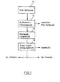
- slag 10 formed as a residue in a waste incinerator is fed to a concentration stage 12, for example via a suitable conveying device (not shown).
- concentration stage In the concentration stage is a detection device which determines which slag particles contain metal.
- the metal-free slag is removed, and free metals and metal-containing slag are fed to a crusher 14.
- a separation stage for FE and non-ferrous metals may be connected. A separation of non-ferrous and ferrous metals can already be made before the waste materials reach the waste incineration plant. However, such a separation is possible only for separately present metal parts, but not in enclosed in the slag metal parts.
- the crushing stage 14 is a crushing or pulverizing the slag, in particular their minerals and the separation of these substances from enclosed metal parts.
- the metal parts remain essentially undeformed or un-shredded during this processing.
- the discharge of the crushing stage 14 is placed in a separation and post-purification stage 16, in which the crushed slag parts are removed.
- the metals can then be separated in a further stage in non-ferrous and ferrous metals.
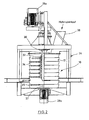
- FIG. 2 a housing 10 can be seen, which consists of a plurality of mutually arranged conical housing sections 12.
- the housing sections 12 are equal in diameter from above.
- the housing 10 is suspended in a frame 24.
- the frame supports in the upper part of a shaft 30 which is driven by an electric drive 28a.
- a sleeve 32 rotatably, are hinged to the six-level chains 34.
- the chains 34 are located at the junctions of the housing sections.
- the chains 34 in the upper housing sections 12 are driven by the drive device 28.
- a chain 35 in the lower housing portion 12 is driven by the lower drive motor 28b, on the shaft of a sleeve 37 is arranged rotationally fixed.
- An upper drive can both chain groups 34, 35 drive over a hollow shaft.
- the drive motors 28a, 28b have opposite directions of rotation.
- both shafts can be arranged as a hollow shaft arrangement on the underside of the housing 10.
- both shafts can be arranged as a hollow shaft arrangement on the underside of the housing 10.
- an upper drive device can drive the rotor elements of the upper groups via a double shaft
- a lower drive device can drive the two lower groups of rotor elements via a double shaft.
- a cover 36 of the housing 10 has a hopper 38 for residues of waste incineration, which are registered via a conveyor (not shown) from above.
- the material falls at least on the rotating chains 34 (e.g., four chains per level) and is struck strikingly.
- the ends of the chains 34, 35 cover the exit diameter of the respective overlying conical section, so that the falling of the respective one housing section in the next housing section material always hits chains, so that it is correspondingly effectively comminuted.
- the free material emerging from the comminuting device 10 reaches a conveying device and is fed to a separating device, not shown in the figure, for metal on the one hand and crushed slag on the other hand.
- the metals remain in lumpy form, at least 95%. Heavy metal contamination is greatly reduced and metal recovery from the residues increased.
- the slag gets a good usable consistency. Landfill costs are lowered significantly. The reaction behavior of the slag is significantly reduced.
Landscapes
- Engineering & Computer Science (AREA)
- Chemical & Material Sciences (AREA)
- Mechanical Engineering (AREA)
- Environmental & Geological Engineering (AREA)
- General Life Sciences & Earth Sciences (AREA)
- Geology (AREA)
- Manufacturing & Machinery (AREA)
- Life Sciences & Earth Sciences (AREA)
- Materials Engineering (AREA)
- Food Science & Technology (AREA)
- Metallurgy (AREA)
- Organic Chemistry (AREA)
- General Engineering & Computer Science (AREA)
- Processing Of Solid Wastes (AREA)
Description
- Die Erfindung bezieht sich auf ein Verfahren und eine Anlage zur Gewinnung von Metallteilen aus Schlacken von Müllverbrennungsprozessen.
- Aus der
DE 100 06 834 A1 ist eine Anlage für die Behandlung von metallhaltigen Verbundstoffen als Behandlungsgut mit einem einer Prallmühle vorgeschalteten Metallabscheider sowie gegebenenfalls einen der Prallmühle folgenden Wirbelstromabscheider als Einrichtung zur Abscheidung von Behandlungsgut durch Verwirbelung bekannt, wobei zum Rückgewinnen von Eisen und Nicht-Eisenmetallen aus der Schlacke einer Müllverbrennungsanlage eine Siebstation sowohl mit ihrem Austrag für Feinkorn als auch mit dem Austrag für das Überkorn jeweils an einen Metallabscheider angeschlossen und dessen Austrag für nichtmagnetisches Haufwerk einer Prallmühle nachgeordnet ist. Bei dem bekannten Verfahren wird Schlacke aus einem Müllverbrennungsverfahren als Behandlungsgut zu Schlackefeinkorn verarbeitet und die Anteile an Eisen und/oder Nicht-Eisenmetallen werden freigelegt und anschließend getrennt. - Ähnliche Verfahren und Anlagen sind aus der
US-A-4044956 , derEP-A-1749804 ,EP-A-0691160 , derJP 09137923 A WO 2007/036362 A sowie derEP-A-0778086 bekannt. - Zur Vermeidung von Deponien ist bekannt, insbesondere Abfälle aus Haushalten zu verbrennen. Dies geschieht in sogenannten Müllverbrennungsanlagen. Es ist auch bereits bekannt, bei der Müllverbrennung Energie zu erzeugen. Dies erfordert eine geeignete Aufbereitung der Abfallstoffe.
- Der Müllverbrennung geht häufig keine Vorsortierung voraus, bei der etwa die im Müll befindlichen Metallteile separiert werden.
- Bei der Müllverbrennung entsteht als Rückstand Schlacke. Metallteile, die noch in die Verbrennungsanlage eingetragen werden, werden zusammen mit der Schlacke aus der Verbrennungsanlage ausgetragen. Da die Temperatur in der Verbrennungsanlage üblicherweise nicht die Schmelztemperatur aller Metalle erreicht, verändern diese normalerweise nicht ihre Ursprungsform. Es ist daher möglich, eine Trennung von Metallteilen und Schlacken durch Magnete und Wirbelstromabscheider vorzunehmen. Allerdings befindet sich eine nicht unerhebliche Menge an Metall in Schlacke eingeschlossen. Außerdem sind noch freie Metalle, die im Wirbelstromabscheider oder durch Magnete nicht ausgeschieden werden, mit Schlacke behaftet, für die der Verwerter von Altmetall keine Verwendung findet.
- Der Erfindung liegt die Aufgabe zugrunde, ein Verfahren zur Gewinnung von Metallteilen aus Schlacken von Müllverbrennungsprozessen zu schaffen, bei dem auch in Schlacken eingeschlossene Metallteile und freie Metallstücke gewonnen werden können, im Wesentlichen ohne diese zu zerstören bzw. zu zerkleinern.
- Diese Aufgabe wird erfindungsgemäßs durch das Verfahren nach Patentanspruchs 1 und durch die Anlage nach Patentanspruch 7 gelöst. Vorteilhafte Weiterbildungen des Erfindung sind Gegen stand der betreffenden abhaingigen Ansprüche 2 bis 2 und 8 bis 11.
- Bei dem erfindungsgemäßen Verfahren wird durch einen Magnet- und Wirbelstromabscheidungsprozeß weitgehend freies Metall von der Schlacke getrennt. Die Schlacke wird anschließend mit Hilfe eines weiteren Verfahrens, insbesondere eines Induktionsmeßverfahrens in metallfreie und Metall enthaltende Schlacke sowie freie Metalle getrennt. Ein solches Verfahren ist grundsätzlich bekannt, etwa aus Artikel "Kompakt, schnell und sauber" im RECYCLING-Magazin 05/2007. Es ist möglich, durch ein geeignetes Detektionsverfahren festzustellen, ob Schlackebrocken Metall in meßbarem Umfang enthalten. Durch eine geeignete Trennmethode, beispielsweise durch Ausblasen mit Druckluft, lassen sich die metallbehafteten Schlackenstücke sowie freie Metalle von den metallfreien trennen. Die Metall enthaltende Schlacke und freie Metalle werden in den oberen Einlauf eines Schachtes einer Zerkleinerungsvorrichtung gegeben, in dem z.B. mindestens eine Gruppe von axial beabstandeten Rotorelementen um eine vertikale Achse drehend angetrieben ist. Vorzugsweise weisen Rotorelemente einer oberen Gruppe eine Drehrichtung auf, die entgegengesetzt zur Drehrichtung von Rotorelementen einer darunter angeordneten Gruppe ist. Die Rotorelemente, beispielsweise Ketten oder dergleichen, wirken schlagend auf die Schlacke ein und schleudern sie außerdem gegen die Wandung des Schachtes. Besonders wirksam ist der gegenläufige Schlagimpuls, wenn die Schlacke von der einen Gruppe der Rotorelemente in die andere übertritt. Dieses Verfahren bewirkt, daß die Schlacke zu körnigem oder pulverförmigem Material zerkleinert wird, während das Metall im Wesentlichen unzerkleinert bleibt. Freie Metallteile werden von anhaftender Schlacke befreit. Schließlich wird das aus dem Auslaß der Zerkleinerungsvorrichtung austretende Material in einem weiteren Schritt separiert, indem die zerkleinerte Schlacke von den Metallteilen getrennt wird. Dies kann über ein Sieb, einen Windsichter oder dergleichen Trennvorrichtungen erfolgen.
- Eine Zerkleinerungsvorrichtung, wie sie obenerwähnt ist, ist grundsätzlich bekannt, etwa aus
WO 2007/036362 . Sie wird zum Zerkleinern von Haufwerk eingesetzt. Mit ihr kann relativ heterogenes, schüttfähiges Material in ein relativ homogenes zerkleinertes Gemisch verwandelt werden. Bei dem erfindungsgemäßen Verfahren wird diese Vorrichtung dazu verwendet, in Schlacke eingeschlossenes Metall und Metallteile von der Schlacke zu befreien und der Verwendung zugänglich zu machen. - Nach einer Ausgestaltung der Erfindung erfolgt in einer weiteren Stufe die Trennung des Metallgemisches durch Separierung von Nichteisen und Eisenmetallen.
- Um das erfindungsgemäße Verfahren effizienter zu gestalten, sieht eine Ausgestaltung der Erfindung vor, daß vor dem Trennen von metallbehafteter Schlacke und freien Metallen von metallfreier Schlacke Unterkorn abgetrennt wird. Das Unterkorn bewegt sich zum Beispiel in der Größe von 0 - 5 mm. Dabei wird von der Erkenntnis ausgegangen, daß sich Metallteile im Unterkorn kaum noch finden und es daher nicht effizient ist, dieses einem Detektions- und Zerkleinerungsprozeß zu unterwerfen. Bei der Entfernung des Unterkorns werden bis zu 40 Masseprozent der Schlacke entfernt.
- Besonders vorteilhaft ist, wenn in der Zerkleinerungsvorrichtung mehr als zwei Gruppen von Rotorelementen nacheinander auf das Gut einwirken, wobei die Rotorelemente benachbarter Gruppen jeweils entgegengesetzten Drehsinn haben.
- Mit der Erfindung wird der Vorteil erhalten, daß aus der Schlacke von Müllverbrennungsprozessen die Metalle weitgehend entfernt werden und dadurch einer Verwertung zugeführt werden können. Ein weiterer und möglicherweise noch größerer Vorteil besteht darin, daß die Schlacke in mehr oder weniger aufbereiteter Form einer weiteren Verwendung zugeführt werden kann, beispielsweise im Tiefbau, da der Anteil schädlicher Metalle, welche einem solchen Einsatz entgegenstehen, stark reduziert ist.
- Die Erfindung wird nachfolgend anhand von Zeichnungen näher beschrieben.
- Fig. 1
- zeigt ein Fließschema zum erfindungsgemäßen Verfahren.
- Fig. 2
- zeigt eine Zerkleinerungsvorrichtung für die Durchführung des erfindungsgemäßen Verfahrens.
- Aus dem Fließschema ist zu erkennen, daß in einer Müllverbrennungseinrichtung als Rückstand gebildete Schlacke 10 einer Aufkonzentrierungsstufe 12 zugeführt wird, zum Beispiel über eine geeignete, nicht gezeigte Fördervorrichtung. In der Aufkonzentrierungsstufe befindet sich eine Detektionsvorrichtung, welche feststellt, in welchen Schlacketeilchen Metall enthalten ist. Die metallfreie Schlacke wird entfernt, und freie Metalle und metallhaltige Schlacke werden einer Zerkleinerungsvorrichtung 14 zugeführt. Es versteht sich, daß zwischen dem Block 10 und der Aufkonzentrationsstufe 12 bereits eine Trennstufe für FE- und NE-Metalle geschaltet sein kann. Eine Trennung von Nichteisen- und Eisenmetallen kann auch bereits vorgenommen werden, bevor die Abfallstoffe in die Müllverbrennungsanlage gelangen. Eine solche Trennung ist jedoch nur bei separat vorliegenden Metallteilen möglich, nicht jedoch bei in der Schlacke eingeschlossenen Metallteilen.
- In der Zerkleinerungsstufe 14 erfolgt ein Zerkleinern oder Pulverisieren der Schlacke, insbesondere deren Mineralstoffen und das Trennen dieser Stoffe von eingeschlossenen Metallteilen. Die Metallteile bleiben bei dieser Bearbeitung im Wesentlichen unverformt bzw. unzerkleinert. Der Austrag der Zerkleinerungsstufe 14 wird in eine Trenn- und Nachreinigungsstufe 16 gegeben, in der die zerkleinerten Schlacketeile entfernt werden. Die Metalle können dann anschließend in einer weiteren Stufe in Nichteisen- und Eisenmetalle getrennt werden.
- In
Figur 2 ist ein Gehäuse 10 zu erkennen, das aus mehreren untereinander angeordneten konischen Gehäuseabschnitten 12 besteht. Die Gehäuseabschnitte 12 sind im Durchmesser von oben gleich. - Das Gehäuse 10 ist in einem Rahmen 24 aufgehängt. Der Rahmen lagert im oberen Bereich eine Welle 30, die von einem Elektroantrieb 28a angetrieben ist. Auf der Welle sitzt eine Hülse 32 drehfest, an der in sechs Ebenen Ketten 34 angelenkt sind. Die Ketten 34 befinden sich an den Übergängen der Gehäuseabschnitte. Die Ketten 34 in den oberen Gehäuseabschnitten 12 werden von der Antriebsvorrichtung 28 angetrieben. Eine Kette 35 im unteren Gehäuseabschnitt 12 wird von dem unteren Antriebsmotor 28b angetrieben, auf dessen Welle eine Hülse 37 drehfest angeordnet ist. Ein oberer Antrieb kann beide Kettengruppen 34, 35 über eine Hohlwelle antreiben. Die Antriebsmotoren 28a, 28b haben entgegengesetzte Drehrichtungen.
- Es ist auch denkbar, beide Wellen als Hohlwellenanordnung an der Unterseite des Gehäuses 10 anzuordnen. Schließlich ist auch denkbar, statt zwei Gruppen, drei oder vier Gruppen von Rotorelementen etwa in Form der Ketten vorzusehen, die jeweils untereinander angeordnet sind. Bei vier Gruppen kann eine obere Antriebsvorrichtung über eine Doppelwelle die Rotorelemente der oberen Gruppen antreiben und eine untere Antriebsvorrichtung die beiden unteren Gruppen Rotorelemente über eine Doppelwelle antreiben.
- Ein Deckel 36 des Gehäuses 10 weist einen Einfülltrichter 38 für Rückstände der Müllverbrennung auf, die über eine Fördervorrichtung (nicht gezeigt) von oben eingetragen werden.
- Wie erkennbar, fällt das Material zumindest auf die rotierenden Ketten 34 (z.B. vier Ketten pro Ebene) und wird schlagend getroffen. Die Enden der Ketten 34, 35 überdecken den Austrittsdurchmesser des jeweils darüber liegenden konischen Abschnitts, sodaß das von dem jeweils einen Gehäuseabschnitt in den nächsten Gehäuseabschnitt fallende Material immer auf Ketten trifft, damit es entsprechend wirksam zerkleinert wird.
- Die von oben eingegebene und im Wesentlichen im freien Fall herunterfallende Schlacke wird durch die umlaufenden Ketten 34, 35 zerkleinert und gegen die Gehäusewandung geschleudert und dort mit einer nicht unerheblichen Umfangsgeschwindigkeit bewegt. Dabei bewegt sich die Schlacke zugleich nach unten. Dadurch trifft das an der Gehäusewand des oberen Gehäuseabschnitts 12 bewegte Material auf die Ketten der darunter liegenden Gehäuseabschnitte und wird dort erneut wirksam zerkleinert. Von besonderer Bedeutung ist, daß beim Übergang von den Ketten 34 zu den Ketten 35 des unteren Gehäuseabschnitts eine Drehrichtungsumkehr des nach unten fallenden Materials stattfindet, wodurch die Zerkleinerungswirkung signifikant erhöht wird. Die Schlacke wird zerkleinert und zerbröselt zu einem feinen, körnigen Material, während das freie und das eingeschlossen gewesene Metall im Wesentlichen unzerkleinert bleibt. Dieses Merkmal ist von Bedeutung, insbesondere im Hinblick auf aus Aluminium bestehenden Teilen. Für die Wiederverwertung von Altaluminium ist wichtig, daß die Teile nicht in zu kleiner Form anfallen. Ist dies der Fall, ist eine Wiederverwertung problematisch.
- Das freie, aus der Zerkleinerungsvorrichtung 10 austretende Material gelangt auf eine Fördervorrichtung und wird einer in der Figur nicht gezeigten Trennvorrichtung für Metall einerseits und zerkleinerter Schlacke andererseits zugeführt.
- Die Metalle bleiben in stückiger Form, mindestens zu 95 %. Die Schwermetallbelastung wird stark reduziert und die Metallrückgewinnung aus den Rückständen gesteigert. Die Schlacke erhält eine gut verwertbare Konsistenz. Deponiekosten werden erhebliche gesenkt. Das Reaktionsverhalten der Schlacke ist deutlich reduziert.
Claims (11)
- Verfahren zur Gewinnung von Metallteilen aus Rückständen von Müllverbrennungsprozessen mit den folgenden Schritten:• mit Hilfe eines Metall-Detektierverfahrens, insbesondere eines Induktiv-Meßverfahren werden die Rückstände in metallfreie und Metall enthaltende Schlacke sowie freie Metalle getrennt,• die Metall enthaltenden Schlacken und freie Metalle werden in den oberen Einlauf eines Schachtes einer Zerkleinerungsvorrichtung (14) gegeben, in dem axial beabstandete, vorzugsweise aus Ketten (34, 35) bestehende Rotorelemente, um eine vertikale Achse drehend angetrieben werden, wobei das Material durch den Schacht von oben nach unten durchfällt, wobei• mineralische Bestandteil der Schlacke zu feinem, körnigem Material zerkleinert und freie Metalie von anhaftender Schlacke befreit werden und die Metallteile im Wesentlichen unzerkleinert bleiben, und• das frei aus dem Schacht herausfallende und aus einem unteren Auslauf der Zerkleinerungsvorrichtung (14) austretende Material wird anschließend nach Metallteilen und dem übrigen Material sortiert.
- Verfahren nach Anspruch 1, bei clem das Material von einer oberen Gruppe von Rotorelementen, die in einer ersten Drehrichtung angetrieben sind, bearbeitet und danach von mindestens einer zweiten Gruppe von Rotorelementen bearbeitet wird, die in der entgegengesetzten Drehrichtung angetrieben werden.
- Verfahren nach Anspruch 1 oder 2, bei dem vor dem Trennen metallhaltiger und metallfreier Schlacke von der Schlacke Unterkorn abgetrennt wird.
- Verfahren nach Anspruch 3, bei dem die Größe des Unterkorns im Bereich von 0 bis 5 mm liegt.
- Verfahren nach einem der Ansprüche 1 bis 4, bei dem das Metallgernisch in NE- und FE-Metalle getrennt wird.
- Verfahren nach einem der Ansprüche 1 bis 5, bei dem die metallhaltige Schlacke von drei oder vier untereinander angeordneten Gruppen von Rotorelementen zerkleinert wird, wobei in benachbaren Gruppen die Rotorelemente gegengesetzten Drehsinn aufweisen.
- Anlage zur Gewinnung von Metallteilen aus Rückständen von Müllverbrennungsprozessen mit den folgenden Merkmalen:• Eine Autkonzentrationsstufe (12) durch die Rückstände mit Hilfe einer ersten Fördervorrichtung hindurchgeführt werden und die eine Metalldetektionsvorrichtung und eine Sortiervorrichtung für freie Metalle und metallhaltige Schlacke aufwexst, wobei die Sortiervorrichtung nach Maßgabe der Signale der Detektionsvorrichtung freie Metalle und metallhaltige Schlacke zu einer zweiten Fördervorrichtung bewegt,• eine Zerkleinerungsvorrichtung (14), nachgeordnet der zweiten Fördervorrichtung mit einem rohrförmigen Schacht, in dessen oberes Ende freie Metalle und metallhaltige Schlacke eingetragen werden und in dem mindestens eine Gruppe von horizontalen, um eine vertikale Achse angetriebenen Rotorelementen, vorzugsweise Ketten, (34, 35) angeordnet ist, und• eine dem Auslauf der Zerkleinerungsvonichtung (14) nachgeordnete Sortiervorrichtung, in der zerkleinerte Schlacke und im Wesentlichen unzerkleinerte Metallteile getrennt werden.
- Anlage nach Anspruch 6, bei clem mindestens zwei Gruppen von Rotorelementen untereinander angeordnet sind, wobei die Drehrichtung der Rotorelemente der Gruppen entgegengesetzt ist.
- Anlage nach Anspruch 7 oder 8, bei dem der Sortiervorrichtung eine weitere Sortierstufe nachgeordnet ist, die FE- und NE-Metalle trennt.
- Anlage nach Anspruch 7 oder 8, bei dem zwei Gruppen von Rotorelementen von einer oberhalb des Schachtes angeordneten Antriebsvorrichtung über eine koaxiale Welle angetrieben sind.
- Anlage nach Anspruch 10, bei dem mindestens eine dritte Gruppe von Rotorelementen von einem unterhalb der Rotorelemente der dritten Gruppe angeordneten Antriebsvorrichtung angetrieben ist.
Applications Claiming Priority (3)
| Application Number | Priority Date | Filing Date | Title |
|---|---|---|---|
| DE200710040225 DE102007040225A1 (de) | 2007-08-25 | 2007-08-25 | Verfahren und Anlage zur Gewinnung von Metallteilen aus Rückständen von Müllverbrennungsprozessen |
| DE102008013661 | 2008-03-11 | ||
| PCT/EP2008/006927 WO2009027062A1 (de) | 2007-08-25 | 2008-08-22 | Verfahren und anlage zur gewinnung von metallteilen aus rückständen von müllverbrennungsprozessen |
Publications (2)
| Publication Number | Publication Date |
|---|---|
| EP2180962A1 EP2180962A1 (de) | 2010-05-05 |
| EP2180962B1 true EP2180962B1 (de) | 2011-10-26 |
Family
ID=40044077
Family Applications (1)
| Application Number | Title | Priority Date | Filing Date |
|---|---|---|---|
| EP20080785684 Active EP2180962B1 (de) | 2007-08-25 | 2008-08-22 | Verfahren und anlage zur gewinnung von metallteilen aus rückständen von müllverbrennungsprozessen |
Country Status (3)
| Country | Link |
|---|---|
| EP (1) | EP2180962B1 (de) |
| AT (1) | ATE530266T1 (de) |
| WO (1) | WO2009027062A1 (de) |
Families Citing this family (1)
| Publication number | Priority date | Publication date | Assignee | Title |
|---|---|---|---|---|
| EP2837424A1 (de) * | 2013-08-13 | 2015-02-18 | TARTECH eco industries AG | Schlackenbrecher |
Family Cites Families (7)
| Publication number | Priority date | Publication date | Assignee | Title |
|---|---|---|---|---|
| FR2303600A1 (fr) * | 1975-03-12 | 1976-10-08 | Rech Geolog Miniere | Procede mecanique de separation des constituants des rejets solides urbains apres degradation thermique ou de rejets industriels similaires |
| DE4423927A1 (de) * | 1994-07-07 | 1996-01-11 | Abb Research Ltd | Verfahren zum Rückgewinnen von Wertstoffen aus Müllverbrennungsschlacke |
| CA2197453C (en) * | 1994-08-22 | 2001-10-30 | Shigeo Fujimoto | Chain beating type crusher |
| JPH09137923A (ja) * | 1995-11-15 | 1997-05-27 | Daido Steel Co Ltd | 廃棄物溶融炉による溶融物の固化処理装置 |
| DE10206834A1 (de) * | 2001-02-19 | 2002-08-29 | Georg Schons | Anlage und Verfahren für die Behandlung von metallhaltigem Haufwerk |
| ITMI20051439A1 (it) * | 2005-07-26 | 2007-01-27 | Astrid Worldwide Lcc | Uso di una matrice ottenuta mediante il trattamento delle scorie di rifiuti solidi urbani per la produzione di aggiunta minerale sostitutiva del cemento nella preparazione del calcestruzzo impianto per la produzione di detta matrice e relativo proced |
| DE202005021545U1 (de) * | 2005-09-28 | 2008-09-04 | Get Hamburg Gmbh | Vorrichtung zum Zerkleinern von Haufwerk |
-
2008
- 2008-08-22 EP EP20080785684 patent/EP2180962B1/de active Active
- 2008-08-22 WO PCT/EP2008/006927 patent/WO2009027062A1/de not_active Ceased
- 2008-08-22 AT AT08785684T patent/ATE530266T1/de active
Also Published As
| Publication number | Publication date |
|---|---|
| WO2009027062A8 (de) | 2009-11-26 |
| WO2009027062A1 (de) | 2009-03-05 |
| EP2180962A1 (de) | 2010-05-05 |
| ATE530266T1 (de) | 2011-11-15 |
Similar Documents
| Publication | Publication Date | Title |
|---|---|---|
| EP1372860B1 (de) | Anlage und verfahren für die behandlung von metallhaltigem haufwerk | |
| DE69816070T2 (de) | Verfahren zur Behandlung von Schredderstaub | |
| DE4123277C1 (en) | Handling waste combustion slag allowing removal of valuable materials - by reducing raw slag material and then removing dust components and wet sorting to separate light fraction | |
| EP0106997B1 (de) | Verfahren zum Aufbereiten von Müllschrott und Einrichtung zu dessen mechanischer Bearbeitung | |
| DE2520358A1 (de) | Verfahren zum rueckgewinnen der bestandteile von schrott und vorrichtung zum ausueben des verfahrens | |
| DE4100346A1 (de) | Verfahren zur mechanischen aufbereitung von unsortiertem geraeteschrott | |
| DE10319786A1 (de) | Verfahren und Vorrichtung zum Behandeln von Stoffen oder Verbundstoffen bzw. Gemischen | |
| EP0884107A2 (de) | Verfahren und Vorrichtung zur Aufbereitung einer Schredderleichtfraktion mit Metallteilen | |
| EP1447138B1 (de) | Aufbereitung von Schlacke aus Kehrichtverbrennungsanlagen | |
| EP0747126B1 (de) | Verfahren und Vorrichtung zur Aufbereitung von Faserbestandteile und Fremdbestandteile enthaltenden Faserstoffen, insbesondere von Alt-Mineralwolle | |
| DE102007040225A1 (de) | Verfahren und Anlage zur Gewinnung von Metallteilen aus Rückständen von Müllverbrennungsprozessen | |
| DE19629473C2 (de) | Verfahren und Vorrichtung zur Aufbereitung eines Kunststoffgemisches | |
| DE10334646B4 (de) | Verfahren und Anlage zur Aufbereitung der Shredderleichtfraktion aus der Zerkleinerung von Schrotten und metallhaltigen Abfällen | |
| DE2939743C2 (de) | Mehrstufige Anlage zur Aufbereitung von Müll | |
| EP1786564B1 (de) | Anlage zur selektiven behandlung von unsortierten oder vorsortierten abfallstoffen | |
| DE3907445C2 (de) | ||
| DE4111130C2 (de) | ||
| EP0125435A2 (de) | Verfahren und Anlage zur Aufbereitung von mit einer Oberflächenbeschichtung versehenen Metallteilen und zur Erzielung von Kugelform aufweisenden Metallteilchen | |
| EP2180962A1 (de) | Verfahren und anlage zur gewinnung von metallteilen aus rückständen von müllverbrennungsprozessen | |
| EP0623390A1 (de) | Verfahren und Anlage zur mechanischen Aufbereitung von Abfallgemischen | |
| DE19915481A1 (de) | Verfahren zur Gewinnung organischer und anorganischer Bestandteile aus Materialien einer Shredderleichtfraktion sowie Anlage zur Durchführung eines entsprechenden Verfahrens | |
| DE10336802B4 (de) | Verfahren und Anlage zum Trennen und Sortieren insbesondere von vorzerkleinerten Stoffen | |
| DE102012204050B4 (de) | Vorrichtung und Verfahren zum Bearbeiten von Silizium-Stücken | |
| EP2984191A1 (de) | Verfahren und vorrichtung zur gewinnung von beimengungen freiem, reinem eisenschrott aus einem gemenge von zerkleinertem metallschrott | |
| EP3411152B1 (de) | Verfahren zum schreddern von feststoff sowie vorrichtung zur durchführung des verfahrens |
Legal Events
| Date | Code | Title | Description |
|---|---|---|---|
| PUAI | Public reference made under article 153(3) epc to a published international application that has entered the european phase |
Free format text: ORIGINAL CODE: 0009012 |
|
| 17P | Request for examination filed |
Effective date: 20100311 |
|
| AK | Designated contracting states |
Kind code of ref document: A1 Designated state(s): AT BE BG CH CY CZ DE DK EE ES FI FR GB GR HR HU IE IS IT LI LT LU LV MC MT NL NO PL PT RO SE SI SK TR |
|
| AX | Request for extension of the european patent |
Extension state: AL BA MK RS |
|
| DAX | Request for extension of the european patent (deleted) | ||
| GRAP | Despatch of communication of intention to grant a patent |
Free format text: ORIGINAL CODE: EPIDOSNIGR1 |
|
| GRAS | Grant fee paid |
Free format text: ORIGINAL CODE: EPIDOSNIGR3 |
|
| GRAA | (expected) grant |
Free format text: ORIGINAL CODE: 0009210 |
|
| AK | Designated contracting states |
Kind code of ref document: B1 Designated state(s): AT BE BG CH CY CZ DE DK EE ES FI FR GB GR HR HU IE IS IT LI LT LU LV MC MT NL NO PL PT RO SE SI SK TR |
|
| REG | Reference to a national code |
Ref country code: GB Ref legal event code: FG4D Free format text: NOT ENGLISH |
|
| REG | Reference to a national code |
Ref country code: CH Ref legal event code: EP |
|
| REG | Reference to a national code |
Ref country code: IE Ref legal event code: FG4D |
|
| REG | Reference to a national code |
Ref country code: DE Ref legal event code: R096 Ref document number: 502008005396 Country of ref document: DE Effective date: 20111229 |
|
| REG | Reference to a national code |
Ref country code: NL Ref legal event code: VDEP Effective date: 20111026 |
|
| LTIE | Lt: invalidation of european patent or patent extension |
Effective date: 20111026 |
|
| REG | Reference to a national code |
Ref country code: CH Ref legal event code: NV Representative=s name: BODENSEEPATENT GMBH |
|
| PG25 | Lapsed in a contracting state [announced via postgrant information from national office to epo] |
Ref country code: IS Free format text: LAPSE BECAUSE OF FAILURE TO SUBMIT A TRANSLATION OF THE DESCRIPTION OR TO PAY THE FEE WITHIN THE PRESCRIBED TIME-LIMIT Effective date: 20120226 Ref country code: NO Free format text: LAPSE BECAUSE OF FAILURE TO SUBMIT A TRANSLATION OF THE DESCRIPTION OR TO PAY THE FEE WITHIN THE PRESCRIBED TIME-LIMIT Effective date: 20120126 Ref country code: LT Free format text: LAPSE BECAUSE OF FAILURE TO SUBMIT A TRANSLATION OF THE DESCRIPTION OR TO PAY THE FEE WITHIN THE PRESCRIBED TIME-LIMIT Effective date: 20111026 |
|
| REG | Reference to a national code |
Ref country code: DE Ref legal event code: R081 Ref document number: 502008005396 Country of ref document: DE Owner name: GET HAMBURG GMBH, DE Free format text: FORMER OWNER: WEINGART UND KUBRAT GMBH, 21035 HAMBURG, DE Effective date: 20120329 Ref country code: DE Ref legal event code: R081 Ref document number: 502008005396 Country of ref document: DE Owner name: WEINGART UND KUBRAT GMBH, DE Free format text: FORMER OWNER: WEINGART UND KUBRAT GMBH, 21035 HAMBURG, DE Effective date: 20120329 |
|
| PG25 | Lapsed in a contracting state [announced via postgrant information from national office to epo] |
Ref country code: SI Free format text: LAPSE BECAUSE OF FAILURE TO SUBMIT A TRANSLATION OF THE DESCRIPTION OR TO PAY THE FEE WITHIN THE PRESCRIBED TIME-LIMIT Effective date: 20111026 Ref country code: SE Free format text: LAPSE BECAUSE OF FAILURE TO SUBMIT A TRANSLATION OF THE DESCRIPTION OR TO PAY THE FEE WITHIN THE PRESCRIBED TIME-LIMIT Effective date: 20111026 Ref country code: PL Free format text: LAPSE BECAUSE OF FAILURE TO SUBMIT A TRANSLATION OF THE DESCRIPTION OR TO PAY THE FEE WITHIN THE PRESCRIBED TIME-LIMIT Effective date: 20111026 Ref country code: GR Free format text: LAPSE BECAUSE OF FAILURE TO SUBMIT A TRANSLATION OF THE DESCRIPTION OR TO PAY THE FEE WITHIN THE PRESCRIBED TIME-LIMIT Effective date: 20120127 Ref country code: LV Free format text: LAPSE BECAUSE OF FAILURE TO SUBMIT A TRANSLATION OF THE DESCRIPTION OR TO PAY THE FEE WITHIN THE PRESCRIBED TIME-LIMIT Effective date: 20111026 Ref country code: HR Free format text: LAPSE BECAUSE OF FAILURE TO SUBMIT A TRANSLATION OF THE DESCRIPTION OR TO PAY THE FEE WITHIN THE PRESCRIBED TIME-LIMIT Effective date: 20111026 Ref country code: PT Free format text: LAPSE BECAUSE OF FAILURE TO SUBMIT A TRANSLATION OF THE DESCRIPTION OR TO PAY THE FEE WITHIN THE PRESCRIBED TIME-LIMIT Effective date: 20120227 Ref country code: NL Free format text: LAPSE BECAUSE OF FAILURE TO SUBMIT A TRANSLATION OF THE DESCRIPTION OR TO PAY THE FEE WITHIN THE PRESCRIBED TIME-LIMIT Effective date: 20111026 |
|
| REG | Reference to a national code |
Ref country code: IE Ref legal event code: FD4D |
|
| PG25 | Lapsed in a contracting state [announced via postgrant information from national office to epo] |
Ref country code: CY Free format text: LAPSE BECAUSE OF FAILURE TO SUBMIT A TRANSLATION OF THE DESCRIPTION OR TO PAY THE FEE WITHIN THE PRESCRIBED TIME-LIMIT Effective date: 20111026 |
|
| PG25 | Lapsed in a contracting state [announced via postgrant information from national office to epo] |
Ref country code: IE Free format text: LAPSE BECAUSE OF FAILURE TO SUBMIT A TRANSLATION OF THE DESCRIPTION OR TO PAY THE FEE WITHIN THE PRESCRIBED TIME-LIMIT Effective date: 20111026 Ref country code: EE Free format text: LAPSE BECAUSE OF FAILURE TO SUBMIT A TRANSLATION OF THE DESCRIPTION OR TO PAY THE FEE WITHIN THE PRESCRIBED TIME-LIMIT Effective date: 20111026 Ref country code: SK Free format text: LAPSE BECAUSE OF FAILURE TO SUBMIT A TRANSLATION OF THE DESCRIPTION OR TO PAY THE FEE WITHIN THE PRESCRIBED TIME-LIMIT Effective date: 20111026 Ref country code: DK Free format text: LAPSE BECAUSE OF FAILURE TO SUBMIT A TRANSLATION OF THE DESCRIPTION OR TO PAY THE FEE WITHIN THE PRESCRIBED TIME-LIMIT Effective date: 20111026 Ref country code: CZ Free format text: LAPSE BECAUSE OF FAILURE TO SUBMIT A TRANSLATION OF THE DESCRIPTION OR TO PAY THE FEE WITHIN THE PRESCRIBED TIME-LIMIT Effective date: 20111026 Ref country code: BG Free format text: LAPSE BECAUSE OF FAILURE TO SUBMIT A TRANSLATION OF THE DESCRIPTION OR TO PAY THE FEE WITHIN THE PRESCRIBED TIME-LIMIT Effective date: 20120126 |
|
| PG25 | Lapsed in a contracting state [announced via postgrant information from national office to epo] |
Ref country code: IT Free format text: LAPSE BECAUSE OF FAILURE TO SUBMIT A TRANSLATION OF THE DESCRIPTION OR TO PAY THE FEE WITHIN THE PRESCRIBED TIME-LIMIT Effective date: 20111026 Ref country code: RO Free format text: LAPSE BECAUSE OF FAILURE TO SUBMIT A TRANSLATION OF THE DESCRIPTION OR TO PAY THE FEE WITHIN THE PRESCRIBED TIME-LIMIT Effective date: 20111026 |
|
| PLBE | No opposition filed within time limit |
Free format text: ORIGINAL CODE: 0009261 |
|
| STAA | Information on the status of an ep patent application or granted ep patent |
Free format text: STATUS: NO OPPOSITION FILED WITHIN TIME LIMIT |
|
| 26N | No opposition filed |
Effective date: 20120727 |
|
| REG | Reference to a national code |
Ref country code: DE Ref legal event code: R097 Ref document number: 502008005396 Country of ref document: DE Effective date: 20120727 |
|
| BERE | Be: lapsed |
Owner name: WEINGART UND KUBRAT G.M.B.H. Effective date: 20120831 |
|
| PG25 | Lapsed in a contracting state [announced via postgrant information from national office to epo] |
Ref country code: MC Free format text: LAPSE BECAUSE OF NON-PAYMENT OF DUE FEES Effective date: 20120831 |
|
| PG25 | Lapsed in a contracting state [announced via postgrant information from national office to epo] |
Ref country code: ES Free format text: LAPSE BECAUSE OF FAILURE TO SUBMIT A TRANSLATION OF THE DESCRIPTION OR TO PAY THE FEE WITHIN THE PRESCRIBED TIME-LIMIT Effective date: 20120206 |
|
| PG25 | Lapsed in a contracting state [announced via postgrant information from national office to epo] |
Ref country code: BE Free format text: LAPSE BECAUSE OF NON-PAYMENT OF DUE FEES Effective date: 20120831 |
|
| PG25 | Lapsed in a contracting state [announced via postgrant information from national office to epo] |
Ref country code: FI Free format text: LAPSE BECAUSE OF FAILURE TO SUBMIT A TRANSLATION OF THE DESCRIPTION OR TO PAY THE FEE WITHIN THE PRESCRIBED TIME-LIMIT Effective date: 20111026 |
|
| PG25 | Lapsed in a contracting state [announced via postgrant information from national office to epo] |
Ref country code: MT Free format text: LAPSE BECAUSE OF FAILURE TO SUBMIT A TRANSLATION OF THE DESCRIPTION OR TO PAY THE FEE WITHIN THE PRESCRIBED TIME-LIMIT Effective date: 20111026 |
|
| PG25 | Lapsed in a contracting state [announced via postgrant information from national office to epo] |
Ref country code: TR Free format text: LAPSE BECAUSE OF FAILURE TO SUBMIT A TRANSLATION OF THE DESCRIPTION OR TO PAY THE FEE WITHIN THE PRESCRIBED TIME-LIMIT Effective date: 20111026 |
|
| PG25 | Lapsed in a contracting state [announced via postgrant information from national office to epo] |
Ref country code: LU Free format text: LAPSE BECAUSE OF NON-PAYMENT OF DUE FEES Effective date: 20120822 |
|
| PG25 | Lapsed in a contracting state [announced via postgrant information from national office to epo] |
Ref country code: HU Free format text: LAPSE BECAUSE OF FAILURE TO SUBMIT A TRANSLATION OF THE DESCRIPTION OR TO PAY THE FEE WITHIN THE PRESCRIBED TIME-LIMIT Effective date: 20080822 |
|
| REG | Reference to a national code |
Ref country code: FR Ref legal event code: PLFP Year of fee payment: 9 |
|
| REG | Reference to a national code |
Ref country code: FR Ref legal event code: PLFP Year of fee payment: 10 |
|
| REG | Reference to a national code |
Ref country code: FR Ref legal event code: PLFP Year of fee payment: 11 |
|
| REG | Reference to a national code |
Ref country code: CH Ref legal event code: PFA Owner name: WEINGART UND KUBRAT GMBH, DE Free format text: FORMER OWNER: WEINGART UND KUBRAT GMBH, DE |
|
| PGFP | Annual fee paid to national office [announced via postgrant information from national office to epo] |
Ref country code: GB Payment date: 20250918 Year of fee payment: 18 |
|
| PGFP | Annual fee paid to national office [announced via postgrant information from national office to epo] |
Ref country code: FR Payment date: 20250827 Year of fee payment: 18 Ref country code: AT Payment date: 20250822 Year of fee payment: 18 |
|
| REG | Reference to a national code |
Ref country code: CH Ref legal event code: U11 Free format text: ST27 STATUS EVENT CODE: U-0-0-U10-U11 (AS PROVIDED BY THE NATIONAL OFFICE) Effective date: 20251120 |
|
| PGFP | Annual fee paid to national office [announced via postgrant information from national office to epo] |
Ref country code: DE Payment date: 20251028 Year of fee payment: 18 |
|
| PGFP | Annual fee paid to national office [announced via postgrant information from national office to epo] |
Ref country code: CH Payment date: 20251120 Year of fee payment: 18 |