EP2181580A1 - Dispositif de rétention de bac de ramassage pour unité de découpage de tondeuse à cylindre - Google Patents
Dispositif de rétention de bac de ramassage pour unité de découpage de tondeuse à cylindre Download PDFInfo
- Publication number
- EP2181580A1 EP2181580A1 EP09173622A EP09173622A EP2181580A1 EP 2181580 A1 EP2181580 A1 EP 2181580A1 EP 09173622 A EP09173622 A EP 09173622A EP 09173622 A EP09173622 A EP 09173622A EP 2181580 A1 EP2181580 A1 EP 2181580A1
- Authority
- EP
- European Patent Office
- Prior art keywords
- grass catcher
- cutting unit
- reel mower
- retaining device
- mower cutting
- Prior art date
- Legal status (The legal status is an assumption and is not a legal conclusion. Google has not performed a legal analysis and makes no representation as to the accuracy of the status listed.)
- Granted
Links
- 244000025254 Cannabis sativa Species 0.000 title claims abstract description 98
- 241001494496 Leersia Species 0.000 description 2
- 230000000717 retained effect Effects 0.000 description 2
- 230000005540 biological transmission Effects 0.000 description 1
- 238000004140 cleaning Methods 0.000 description 1
- 230000009194 climbing Effects 0.000 description 1
- 238000010276 construction Methods 0.000 description 1
- 230000001419 dependent effect Effects 0.000 description 1
- 230000000694 effects Effects 0.000 description 1
- 230000002706 hydrostatic effect Effects 0.000 description 1
- 238000009434 installation Methods 0.000 description 1
- 239000002184 metal Substances 0.000 description 1
- 201000009482 yaws Diseases 0.000 description 1
Images


Classifications
-
- A—HUMAN NECESSITIES
- A01—AGRICULTURE; FORESTRY; ANIMAL HUSBANDRY; HUNTING; TRAPPING; FISHING
- A01D—HARVESTING; MOWING
- A01D43/00—Mowers combined with apparatus performing additional operations while mowing
- A01D43/06—Mowers combined with apparatus performing additional operations while mowing with means for collecting, gathering or loading mown material
- A01D43/063—Mowers combined with apparatus performing additional operations while mowing with means for collecting, gathering or loading mown material in or into a container carried by the mower; Containers therefor
Definitions
- This invention relates generally to grass mowing equipment, and more specifically to a grass catcher retaining device for a reel mower cutting unit.
- a grass catcher may be mounted directly in front of a reel mower cutting unit to collect grass clippings discharged from the cutting unit as it moves forward in the mowing position.
- Grass mowing machines such as fairway mowers, trim mowers and triplex riding greensmowers may have reel mower cutting units that can pivot on one or more axes of rotation.
- each reel mower cutting unit may be mounted to a lift arm extending from a traction unit so that the cutting unit can pitch on a horizontal axis parallel to the reel, roll on a horizontal axis in the direction of travel, and/or yaw or steer on a vertical axis.
- the pivoting action allows the cutting unit to better follow the ground surface, avoid scalping, and provide a more uniform height of cut.
- grass catcher retaining devices have been designed to allow the grass catcher to pivot and move along with the reel mower cutting unit. Additionally, some grass catchers are mounted to a separate frame or to the grass mowing machine traction unit so that the reel mower cutting unit itself does not support the weight of the grass catcher.
- US 5 533 326 A and US 6 341 478 A relate to a triplex greensmower having a grass catcher mounted on a carrier frame in front of each reel mower cutting unit, with a pair of horns supporting the ends of the grass catcher.
- the '478 patent also relates to a pivot axis connection that is located forwardly and above the cutting unit so the grass catcher can yaw or steer.
- grass mowing machines have retaining devices in which the reel mower cutting unit substantially supports the grass catcher. These machines include walk behind greensmowers in which the cutting unit helps support the frame or traction unit in the mowing position. Additionally, fairway mowers may have reel mower cutting units that substantially support the weight of both the lift arm and the grass catcher attached to the lift arm.
- a grass catcher retaining device offered by Deere & Company on riding greensmowers includes a hook extending forwardly from the traction unit frame, which may be connected to a handle on a bail under the grass catcher.
- the bail is pivotably mounted to the reel mower cutting unit, allowing the grass catcher to pitch on a horizontal axis with respect to the reel.
- the handle slides on the hook as the grass catcher yaws or steers with the cutting unit.
- an operator must position the grass catcher on the bail, and then fasten or latch the hook to the handle.
- To remove the grass catcher the operator must reverse the two actions.
- An improved grass catcher retaining device is needed that can be installed or removed more easily, using only one hand.
- US 5 412 931 A relates to a slidable grass catcher with a laterally extending rail on the cutting unit, and a pair of hooks on the grass catcher that engage the rail.
- US 6 237 313 A relates to a grass catcher support assembly that includes upper and lower support members at each side of the cutting unit that support the grass catcher, with cables attached between the upper and lower support members.
- An improved grass catcher retaining device is needed that can hold the grass catcher in a position relative to the reel mower cutting unit such that the open edge of the grass catcher stays in a fixed position relative to the cutting unit while still allowing motion of the catcher and reel to accommodate varying terrain.
- a grass catcher retaining device for a reel mower cutting unit.
- the retaining device includes a central support ring pivotably attached to the top center of the grass catcher.
- the central support ring may include a gate that allows the ring to be latched onto a wireform loop that extends forwardly from the lift arm.
- the gate may be biased to a closed position.
- the central support ring may be pivotably mounted to the grass catcher on an axis parallel to the reel mower. Additionally, a rod may extend from each side of the grass catcher, and may engage a slot in the reel mower cutting unit.
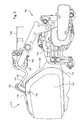
- reel mower cutting unit 100 may be rotated by electric motor 101 mounted to one of side panels 102 on the left and right sides of the cutting unit.
- the reel mower cutting unit may be driven directly or indirectly by the engine through a mechanical or hydrostatic transmission.
- the blades of the reel mower cutting unit rotate about a generally horizontal and laterally extending axis. Grass may be cut between the rotating reel blades of cutting reel 110 and a bedknife mounted between the side panels.
- the horizontally aligned cutting reel interacts with a bedknife to cut grass with a scissoring action.
- the reel mower cutting unit is carried by front and rear rollers coupled to the side panels and contacting the ground during mowing operations.
- the front and rear rollers may be adjusted up or down to change the cutting height. While the reel mower cutting unit is on the ground in the mowing position, the cutting unit helps support the frame.
- reel mower cutting unit 100 may be pivotably connected to a forward extending portion of lift arm 105 that is pivotably connected to the frame of a triplex riding greensmower, fairway mower or trim mower.
- the lift arm may be pivotably connected to the reel mower cutting unit with yoke 106.
- the yoke may pull the cutting unit during mowing operations, and may have a ball joint 107 allowing the cutting unit to follow the contours of the ground surface and cut grass at a specified height.
- the reel mower cutting unit may pitch on a horizontal axis parallel to the reel, roll on a horizontal axis perpendicular to the direction of travel, and steer or yaw on a vertical axis.
- grass catcher 112 may be positioned directly in front of reel mower cutting unit 100.
- Grass catcher 112 may have opposing sides 114, lower wall or panel 116, and upper wall or panel 118. Opening 120 may face the reel mower cutting unit to receive grass clippings discharged by the cutting unit.
- the lower wall or panel of the grass catcher may extend over the front roller of the cutting unit.
- lift arm 105 may be hydraulically or electrically actuated to raise and lower the reel mower cutting unit between a mowing position and a transport position.
- the cutting unit and grass catcher may remain in a horizontal alignment as they are raised or lowered, or they may pivot to a vertical orientation during transport. Additionally, one or more cutting units may be rotated to a service position.
- the grass catcher may be retained on the reel mower cutting unit by center support ring 130.
- the center support ring may provide all or a high percentage of the support for the weight of the grass catcher and clippings.
- the center support ring may remain fastened between the reel mower cutting unit and grass catcher while they are raised or lowered, or at any intermediate position or alignment of the cutting unit.
- center support ring 130 may be an oblong metal or plastic loop with a gate 131 that is spring loaded to a closed position.
- the center support ring may be pivotably attached to the top center portion of the grass catcher so that the ring can pivot on a horizontal axis parallel to the cutting reel and perpendicular to the direction of travel of the grass mowing machine and cutting unit.
- the pivot axis may be a horizontally mounted threaded fastener 133 in or adjacent the top panel 118 of the grass catcher.
- gate 131 may open and close so that an operator may fasten the center support ring around wireform loop 132 which extends forwardly from the yoke.
- the wireform loop may have a pair of ends fastened to the yoke using threaded fasteners.
- center support ring 130 may be a carabiner that is typically used in activities requiring ropework, such as mountain climbing or sailing, and in industrial rope access work, such as construction or window cleaning.
- the carabiner includes gate 131 that may snap shut under a spring's pressure, and may be nonlocking so that an operator can remove or install the carabiner on the wireform loop with one hand.
- the center support ring is free to rotate and slide with respect to the lift arm and wire form loop so that the grass catcher can accommodate varying terrain while maintaining a positive and secure connection between the grass catcher and the reel mower cutting unit.
- the center support ring allows a grass catcher to hang on the yoke of the reel mower cutting unit, and transfers a large proportion of the grass catcher's weight to the lift arm and yoke, as opposed to the cutting unit. As a result, the center support ring minimizes any influence the grass catcher may impart to the cutting unit.
- the center support ring also significantly reduces the complexity of the grass catcher support and allows one handed removal or installation.
- the center support ring provides a positive connection between the grass catcher and yoke while also providing a free range of motion.
- rod 166 may extend horizontally from the sides of the grass catcher at or near lower wall or panel 116.
- each end of the rod can enter a slot 167 in the side panel of the cutting unit.
- the rod provides a horizontal pivot axis between the grass catcher and the reel mower cutting unit, parallel to the cutting reel, allowing the grass catcher to pitch with respect to the cutting unit.
- the grass catcher may pitch independently of the reel mower cutting unit if undulations or obstacles are encountered by the grass catcher before the cutting unit.
- the rod may provide an axis and a pair of pivot points that are integral with the grass catcher.
- an operator may install the grass catcher by inserting each end of rod 166 into a slot 167 in the side panel of the reel mower cutting unit, and then fastening the center support ring onto the wireform.
- Each slot 167 may be inclined forwardly and/or tapered so that an operator can easily install and remove the grass catcher from the reel mower cutting unit.
- the left and right ends of the rod help maintain the grass catcher in close proximity to the reel mower cutting unit while allowing the grass catcher to pitch with respect to the cutting unit.
- the grass catcher retaining device may be used on any grass mowing machine having one or more reel mower cutting units.
- the retaining device may be used for reel mower cutting units on triplex riding greensmowers, trim mowers, or walk behind greensmowers.
Landscapes
- Life Sciences & Earth Sciences (AREA)
- Environmental Sciences (AREA)
- Harvester Elements (AREA)
Applications Claiming Priority (1)
| Application Number | Priority Date | Filing Date | Title |
|---|---|---|---|
| US12/261,378 US7845152B2 (en) | 2008-10-30 | 2008-10-30 | Grass catcher retaining device for reel mower cutting unit |
Publications (2)
| Publication Number | Publication Date |
|---|---|
| EP2181580A1 true EP2181580A1 (fr) | 2010-05-05 |
| EP2181580B1 EP2181580B1 (fr) | 2012-07-04 |
Family
ID=41559174
Family Applications (1)
| Application Number | Title | Priority Date | Filing Date |
|---|---|---|---|
| EP09173622A Active EP2181580B1 (fr) | 2008-10-30 | 2009-10-21 | Tondeuse à cylindre |
Country Status (2)
| Country | Link |
|---|---|
| US (1) | US7845152B2 (fr) |
| EP (1) | EP2181580B1 (fr) |
Cited By (2)
| Publication number | Priority date | Publication date | Assignee | Title |
|---|---|---|---|---|
| EP2702857A1 (fr) * | 2012-08-31 | 2014-03-05 | Deere & Company | Support de collecteur d'herbe de tondeuse à lames rotatives |
| EP3446557A3 (fr) * | 2017-08-25 | 2019-06-26 | Deere & Company | Tondeuse à gazon à conducteur debout comportant de multiples unités de coupe |
Families Citing this family (2)
| Publication number | Priority date | Publication date | Assignee | Title |
|---|---|---|---|---|
| US9027318B2 (en) * | 2012-02-07 | 2015-05-12 | IHI Shibaura Machinery Corporation | Reel lawn mower with main body, reel cutting unit, and connection structure for connecting reel cutting unit to main body such that reel cutting unit is rollable |
| US9854740B2 (en) * | 2015-06-27 | 2018-01-02 | The Toro Company | Reel mower with reel cutting units having grass collecting baskets with deflectable bottom portions responsive to movement of the cutting units |
Citations (8)
| Publication number | Priority date | Publication date | Assignee | Title |
|---|---|---|---|---|
| US2124835A (en) * | 1937-01-29 | 1938-07-26 | Strutz Edward Henry | Snap hook for attaching grass catchers to lawn mowers |
| US3002332A (en) * | 1957-03-19 | 1961-10-03 | Nathaniel C Shane | Grass catcher and guard for lawn mowers |
| US5412931A (en) | 1993-08-12 | 1995-05-09 | Deere & Company | Slidable grass catcher |
| US5533326A (en) | 1995-02-24 | 1996-07-09 | The Toro Company | Reel mower |
| US6237313B1 (en) | 1999-08-13 | 2001-05-29 | Deere & Company | Grass catcher support assembly for reel mower cutting unit |
| US6341478B1 (en) | 1999-06-14 | 2002-01-29 | The Toro Company | Steerable cutting unit with steerable and level lift grass catcher |
| EP1537769A1 (fr) * | 2003-12-05 | 2005-06-08 | Deere & Company | Collecteur d'herbe et appareil |
| EP2082640A1 (fr) * | 2008-01-25 | 2009-07-29 | Deere & Company | Dispositif d'assemblage de bac de ramassage |
Family Cites Families (10)
| Publication number | Priority date | Publication date | Assignee | Title |
|---|---|---|---|---|
| US3110147A (en) | 1961-06-12 | 1963-11-12 | Jacobsen Mfg Co | Reel type lawn mower with catcher |
| US3408801A (en) | 1965-10-22 | 1968-11-05 | Toro Mfg Corp | Non-spill grass catcher |
| US3516233A (en) * | 1969-05-07 | 1970-06-23 | Fay O Johnson | Lightweight rideable green mower |
| US4970852A (en) | 1989-02-09 | 1990-11-20 | The Toro Company | Grass catcher for reel mower |
| US4924663A (en) | 1989-05-08 | 1990-05-15 | Textron, Inc. | Mower-mounted grass catcher and reel lawn mower assembly and method of making same |
| US5228277A (en) * | 1992-01-23 | 1993-07-20 | Deere & Company | Rear discharge reel mower having multi-purpose rotary brush |
| US5412932A (en) * | 1994-08-10 | 1995-05-09 | Textron Inc. | Motor-powered lawn mower |
| ATE355731T1 (de) * | 2000-06-26 | 2007-03-15 | Toro Co | Spindelmäher |
| US7331166B2 (en) * | 2005-01-28 | 2008-02-19 | Deere & Company | Coupling mechanism for mower cutting units |
| JP2009027961A (ja) * | 2007-07-26 | 2009-02-12 | Kyoeisha Co Ltd | 歩行式芝刈機、及びキャッチャーフレーム装置 |
-
2008
- 2008-10-30 US US12/261,378 patent/US7845152B2/en active Active
-
2009
- 2009-10-21 EP EP09173622A patent/EP2181580B1/fr active Active
Patent Citations (8)
| Publication number | Priority date | Publication date | Assignee | Title |
|---|---|---|---|---|
| US2124835A (en) * | 1937-01-29 | 1938-07-26 | Strutz Edward Henry | Snap hook for attaching grass catchers to lawn mowers |
| US3002332A (en) * | 1957-03-19 | 1961-10-03 | Nathaniel C Shane | Grass catcher and guard for lawn mowers |
| US5412931A (en) | 1993-08-12 | 1995-05-09 | Deere & Company | Slidable grass catcher |
| US5533326A (en) | 1995-02-24 | 1996-07-09 | The Toro Company | Reel mower |
| US6341478B1 (en) | 1999-06-14 | 2002-01-29 | The Toro Company | Steerable cutting unit with steerable and level lift grass catcher |
| US6237313B1 (en) | 1999-08-13 | 2001-05-29 | Deere & Company | Grass catcher support assembly for reel mower cutting unit |
| EP1537769A1 (fr) * | 2003-12-05 | 2005-06-08 | Deere & Company | Collecteur d'herbe et appareil |
| EP2082640A1 (fr) * | 2008-01-25 | 2009-07-29 | Deere & Company | Dispositif d'assemblage de bac de ramassage |
Cited By (3)
| Publication number | Priority date | Publication date | Assignee | Title |
|---|---|---|---|---|
| EP2702857A1 (fr) * | 2012-08-31 | 2014-03-05 | Deere & Company | Support de collecteur d'herbe de tondeuse à lames rotatives |
| US9027317B2 (en) | 2012-08-31 | 2015-05-12 | Deere & Company | Reel mower grass catcher carrier |
| EP3446557A3 (fr) * | 2017-08-25 | 2019-06-26 | Deere & Company | Tondeuse à gazon à conducteur debout comportant de multiples unités de coupe |
Also Published As
| Publication number | Publication date |
|---|---|
| US7845152B2 (en) | 2010-12-07 |
| EP2181580B1 (fr) | 2012-07-04 |
| US20100107586A1 (en) | 2010-05-06 |
Similar Documents
| Publication | Publication Date | Title |
|---|---|---|
| US8407976B2 (en) | Grass catcher mounting device for reel mower cutting unit | |
| US9938104B2 (en) | Apparatus and methods for facilitating the removal of existing turf and installing new turf | |
| US9010450B2 (en) | Apparatus and methods for facilitating the removal of existing turf and installing new turf | |
| US9220193B2 (en) | Reel mower with easily removable cutting units having easily removable motors | |
| US8973343B2 (en) | Mower deck trimmer assembly | |
| EP2181580B1 (fr) | Tondeuse à cylindre | |
| US9320202B2 (en) | Debris removal system for a lawn mower | |
| JP6124199B2 (ja) | 根菜類収穫機 | |
| US9526217B2 (en) | Disk saw felling head with visibility window | |
| EP2156726B1 (fr) | Mécanisme de loquet | |
| EP2702857B1 (fr) | Support de collecteur d'herbe de tondeuse à lames rotatives | |
| CN109379988A (zh) | 三联割草机的开放式脚平台 | |
| US7334387B2 (en) | Adjustable sidekick trimmer device mounted on a tractor or a like vehicle for trimming the edges of a lawn | |
| US20140215994A1 (en) | Reel mower grass catcher carrier | |
| US20030019201A1 (en) | Floating deck material collection system | |
| EP3646695B1 (fr) | Couvercle de plateforme pour pied ouverte de tondeuse de green triplex | |
| JP3511079B2 (ja) | 芝刈作業機 | |
| US6000204A (en) | Golf tee marker moving system | |
| US20060218890A1 (en) | Method and apparatus for grooming a grass lawn | |
| JP2936313B2 (ja) | レール式両面裾刈機 | |
| JP3522515B2 (ja) | 歩行型草刈機 | |
| JPH05184222A (ja) | 藺草収穫機 | |
| JP2000139169A (ja) | 刈取収穫機における分草装置 | |
| JPH07203707A (ja) | い草苗の掘取方法及びい草苗の掘取機 |
Legal Events
| Date | Code | Title | Description |
|---|---|---|---|
| PUAI | Public reference made under article 153(3) epc to a published international application that has entered the european phase |
Free format text: ORIGINAL CODE: 0009012 |
|
| AK | Designated contracting states |
Kind code of ref document: A1 Designated state(s): AT BE BG CH CY CZ DE DK EE ES FI FR GB GR HR HU IE IS IT LI LT LU LV MC MK MT NL NO PL PT RO SE SI SK SM TR |
|
| 17P | Request for examination filed |
Effective date: 20101105 |
|
| 17Q | First examination report despatched |
Effective date: 20101206 |
|
| GRAP | Despatch of communication of intention to grant a patent |
Free format text: ORIGINAL CODE: EPIDOSNIGR1 |
|
| RTI1 | Title (correction) |
Free format text: REEL MOWER CUTTING UNIT |
|
| GRAS | Grant fee paid |
Free format text: ORIGINAL CODE: EPIDOSNIGR3 |
|
| GRAA | (expected) grant |
Free format text: ORIGINAL CODE: 0009210 |
|
| AK | Designated contracting states |
Kind code of ref document: B1 Designated state(s): AT BE BG CH CY CZ DE DK EE ES FI FR GB GR HR HU IE IS IT LI LT LU LV MC MK MT NL NO PL PT RO SE SI SK SM TR |
|
| REG | Reference to a national code |
Ref country code: GB Ref legal event code: FG4D |
|
| REG | Reference to a national code |
Ref country code: CH Ref legal event code: EP |
|
| REG | Reference to a national code |
Ref country code: AT Ref legal event code: REF Ref document number: 564753 Country of ref document: AT Kind code of ref document: T Effective date: 20120715 |
|
| REG | Reference to a national code |
Ref country code: IE Ref legal event code: FG4D |
|
| REG | Reference to a national code |
Ref country code: DE Ref legal event code: R096 Ref document number: 602009008005 Country of ref document: DE Effective date: 20120830 |
|
| REG | Reference to a national code |
Ref country code: AT Ref legal event code: MK05 Ref document number: 564753 Country of ref document: AT Kind code of ref document: T Effective date: 20120704 |
|
| REG | Reference to a national code |
Ref country code: NL Ref legal event code: VDEP Effective date: 20120704 |
|
| PG25 | Lapsed in a contracting state [announced via postgrant information from national office to epo] |
Ref country code: SI Free format text: LAPSE BECAUSE OF FAILURE TO SUBMIT A TRANSLATION OF THE DESCRIPTION OR TO PAY THE FEE WITHIN THE PRESCRIBED TIME-LIMIT Effective date: 20120704 |
|
| REG | Reference to a national code |
Ref country code: LT Ref legal event code: MG4D Effective date: 20120704 |
|
| PG25 | Lapsed in a contracting state [announced via postgrant information from national office to epo] |
Ref country code: LT Free format text: LAPSE BECAUSE OF FAILURE TO SUBMIT A TRANSLATION OF THE DESCRIPTION OR TO PAY THE FEE WITHIN THE PRESCRIBED TIME-LIMIT Effective date: 20120704 Ref country code: NO Free format text: LAPSE BECAUSE OF FAILURE TO SUBMIT A TRANSLATION OF THE DESCRIPTION OR TO PAY THE FEE WITHIN THE PRESCRIBED TIME-LIMIT Effective date: 20121004 Ref country code: CY Free format text: LAPSE BECAUSE OF FAILURE TO SUBMIT A TRANSLATION OF THE DESCRIPTION OR TO PAY THE FEE WITHIN THE PRESCRIBED TIME-LIMIT Effective date: 20120704 Ref country code: IS Free format text: LAPSE BECAUSE OF FAILURE TO SUBMIT A TRANSLATION OF THE DESCRIPTION OR TO PAY THE FEE WITHIN THE PRESCRIBED TIME-LIMIT Effective date: 20121104 Ref country code: BE Free format text: LAPSE BECAUSE OF FAILURE TO SUBMIT A TRANSLATION OF THE DESCRIPTION OR TO PAY THE FEE WITHIN THE PRESCRIBED TIME-LIMIT Effective date: 20120704 Ref country code: AT Free format text: LAPSE BECAUSE OF FAILURE TO SUBMIT A TRANSLATION OF THE DESCRIPTION OR TO PAY THE FEE WITHIN THE PRESCRIBED TIME-LIMIT Effective date: 20120704 Ref country code: HR Free format text: LAPSE BECAUSE OF FAILURE TO SUBMIT A TRANSLATION OF THE DESCRIPTION OR TO PAY THE FEE WITHIN THE PRESCRIBED TIME-LIMIT Effective date: 20120704 Ref country code: FI Free format text: LAPSE BECAUSE OF FAILURE TO SUBMIT A TRANSLATION OF THE DESCRIPTION OR TO PAY THE FEE WITHIN THE PRESCRIBED TIME-LIMIT Effective date: 20120704 |
|
| PG25 | Lapsed in a contracting state [announced via postgrant information from national office to epo] |
Ref country code: LV Free format text: LAPSE BECAUSE OF FAILURE TO SUBMIT A TRANSLATION OF THE DESCRIPTION OR TO PAY THE FEE WITHIN THE PRESCRIBED TIME-LIMIT Effective date: 20120704 Ref country code: PT Free format text: LAPSE BECAUSE OF FAILURE TO SUBMIT A TRANSLATION OF THE DESCRIPTION OR TO PAY THE FEE WITHIN THE PRESCRIBED TIME-LIMIT Effective date: 20121105 Ref country code: GR Free format text: LAPSE BECAUSE OF FAILURE TO SUBMIT A TRANSLATION OF THE DESCRIPTION OR TO PAY THE FEE WITHIN THE PRESCRIBED TIME-LIMIT Effective date: 20121005 Ref country code: PL Free format text: LAPSE BECAUSE OF FAILURE TO SUBMIT A TRANSLATION OF THE DESCRIPTION OR TO PAY THE FEE WITHIN THE PRESCRIBED TIME-LIMIT Effective date: 20120704 Ref country code: SE Free format text: LAPSE BECAUSE OF FAILURE TO SUBMIT A TRANSLATION OF THE DESCRIPTION OR TO PAY THE FEE WITHIN THE PRESCRIBED TIME-LIMIT Effective date: 20120704 |
|
| PG25 | Lapsed in a contracting state [announced via postgrant information from national office to epo] |
Ref country code: NL Free format text: LAPSE BECAUSE OF FAILURE TO SUBMIT A TRANSLATION OF THE DESCRIPTION OR TO PAY THE FEE WITHIN THE PRESCRIBED TIME-LIMIT Effective date: 20120704 |
|
| PG25 | Lapsed in a contracting state [announced via postgrant information from national office to epo] |
Ref country code: DK Free format text: LAPSE BECAUSE OF FAILURE TO SUBMIT A TRANSLATION OF THE DESCRIPTION OR TO PAY THE FEE WITHIN THE PRESCRIBED TIME-LIMIT Effective date: 20120704 Ref country code: EE Free format text: LAPSE BECAUSE OF FAILURE TO SUBMIT A TRANSLATION OF THE DESCRIPTION OR TO PAY THE FEE WITHIN THE PRESCRIBED TIME-LIMIT Effective date: 20120704 Ref country code: RO Free format text: LAPSE BECAUSE OF FAILURE TO SUBMIT A TRANSLATION OF THE DESCRIPTION OR TO PAY THE FEE WITHIN THE PRESCRIBED TIME-LIMIT Effective date: 20120704 Ref country code: ES Free format text: LAPSE BECAUSE OF FAILURE TO SUBMIT A TRANSLATION OF THE DESCRIPTION OR TO PAY THE FEE WITHIN THE PRESCRIBED TIME-LIMIT Effective date: 20121015 Ref country code: CZ Free format text: LAPSE BECAUSE OF FAILURE TO SUBMIT A TRANSLATION OF THE DESCRIPTION OR TO PAY THE FEE WITHIN THE PRESCRIBED TIME-LIMIT Effective date: 20120704 |
|
| PLBE | No opposition filed within time limit |
Free format text: ORIGINAL CODE: 0009261 |
|
| STAA | Information on the status of an ep patent application or granted ep patent |
Free format text: STATUS: NO OPPOSITION FILED WITHIN TIME LIMIT |
|
| PG25 | Lapsed in a contracting state [announced via postgrant information from national office to epo] |
Ref country code: IT Free format text: LAPSE BECAUSE OF FAILURE TO SUBMIT A TRANSLATION OF THE DESCRIPTION OR TO PAY THE FEE WITHIN THE PRESCRIBED TIME-LIMIT Effective date: 20120704 Ref country code: SK Free format text: LAPSE BECAUSE OF FAILURE TO SUBMIT A TRANSLATION OF THE DESCRIPTION OR TO PAY THE FEE WITHIN THE PRESCRIBED TIME-LIMIT Effective date: 20120704 Ref country code: MC Free format text: LAPSE BECAUSE OF NON-PAYMENT OF DUE FEES Effective date: 20121031 |
|
| 26N | No opposition filed |
Effective date: 20130405 |
|
| REG | Reference to a national code |
Ref country code: IE Ref legal event code: MM4A |
|
| REG | Reference to a national code |
Ref country code: FR Ref legal event code: ST Effective date: 20130628 |
|
| PG25 | Lapsed in a contracting state [announced via postgrant information from national office to epo] |
Ref country code: BG Free format text: LAPSE BECAUSE OF FAILURE TO SUBMIT A TRANSLATION OF THE DESCRIPTION OR TO PAY THE FEE WITHIN THE PRESCRIBED TIME-LIMIT Effective date: 20121004 Ref country code: IE Free format text: LAPSE BECAUSE OF NON-PAYMENT OF DUE FEES Effective date: 20121021 |
|
| REG | Reference to a national code |
Ref country code: DE Ref legal event code: R097 Ref document number: 602009008005 Country of ref document: DE Effective date: 20130405 |
|
| PG25 | Lapsed in a contracting state [announced via postgrant information from national office to epo] |
Ref country code: FR Free format text: LAPSE BECAUSE OF NON-PAYMENT OF DUE FEES Effective date: 20121031 |
|
| PG25 | Lapsed in a contracting state [announced via postgrant information from national office to epo] |
Ref country code: MT Free format text: LAPSE BECAUSE OF FAILURE TO SUBMIT A TRANSLATION OF THE DESCRIPTION OR TO PAY THE FEE WITHIN THE PRESCRIBED TIME-LIMIT Effective date: 20120704 |
|
| PG25 | Lapsed in a contracting state [announced via postgrant information from national office to epo] |
Ref country code: TR Free format text: LAPSE BECAUSE OF FAILURE TO SUBMIT A TRANSLATION OF THE DESCRIPTION OR TO PAY THE FEE WITHIN THE PRESCRIBED TIME-LIMIT Effective date: 20120704 |
|
| PG25 | Lapsed in a contracting state [announced via postgrant information from national office to epo] |
Ref country code: SM Free format text: LAPSE BECAUSE OF FAILURE TO SUBMIT A TRANSLATION OF THE DESCRIPTION OR TO PAY THE FEE WITHIN THE PRESCRIBED TIME-LIMIT Effective date: 20120704 Ref country code: LU Free format text: LAPSE BECAUSE OF NON-PAYMENT OF DUE FEES Effective date: 20121021 |
|
| REG | Reference to a national code |
Ref country code: CH Ref legal event code: PL |
|
| PG25 | Lapsed in a contracting state [announced via postgrant information from national office to epo] |
Ref country code: LI Free format text: LAPSE BECAUSE OF NON-PAYMENT OF DUE FEES Effective date: 20131031 Ref country code: HU Free format text: LAPSE BECAUSE OF FAILURE TO SUBMIT A TRANSLATION OF THE DESCRIPTION OR TO PAY THE FEE WITHIN THE PRESCRIBED TIME-LIMIT Effective date: 20091021 Ref country code: CH Free format text: LAPSE BECAUSE OF NON-PAYMENT OF DUE FEES Effective date: 20131031 |
|
| PG25 | Lapsed in a contracting state [announced via postgrant information from national office to epo] |
Ref country code: MK Free format text: LAPSE BECAUSE OF FAILURE TO SUBMIT A TRANSLATION OF THE DESCRIPTION OR TO PAY THE FEE WITHIN THE PRESCRIBED TIME-LIMIT Effective date: 20120704 |
|
| PGFP | Annual fee paid to national office [announced via postgrant information from national office to epo] |
Ref country code: DE Payment date: 20190919 Year of fee payment: 11 |
|
| REG | Reference to a national code |
Ref country code: DE Ref legal event code: R119 Ref document number: 602009008005 Country of ref document: DE |
|
| PG25 | Lapsed in a contracting state [announced via postgrant information from national office to epo] |
Ref country code: DE Free format text: LAPSE BECAUSE OF NON-PAYMENT OF DUE FEES Effective date: 20210501 |
|
| PGFP | Annual fee paid to national office [announced via postgrant information from national office to epo] |
Ref country code: GB Payment date: 20241028 Year of fee payment: 16 |