EP2181662A2 - Dispositif de rayonnement lumineux et dispositif d'entraînement doté d'une diode lumineuse - Google Patents
Dispositif de rayonnement lumineux et dispositif d'entraînement doté d'une diode lumineuse Download PDFInfo
- Publication number
- EP2181662A2 EP2181662A2 EP09013096A EP09013096A EP2181662A2 EP 2181662 A2 EP2181662 A2 EP 2181662A2 EP 09013096 A EP09013096 A EP 09013096A EP 09013096 A EP09013096 A EP 09013096A EP 2181662 A2 EP2181662 A2 EP 2181662A2
- Authority
- EP
- European Patent Office
- Prior art keywords
- layer
- light emitting
- light
- emitting diode
- heat
- Prior art date
- Legal status (The legal status is an assumption and is not a legal conclusion. Google has not performed a legal analysis and makes no representation as to the accuracy of the status listed.)
- Withdrawn
Links
Images


Classifications
-
- A—HUMAN NECESSITIES
- A61—MEDICAL OR VETERINARY SCIENCE; HYGIENE
- A61C—DENTISTRY; APPARATUS OR METHODS FOR ORAL OR DENTAL HYGIENE
- A61C1/00—Dental machines for boring or cutting ; General features of dental machines or apparatus, e.g. hand-piece design
- A61C1/08—Machine parts specially adapted for dentistry
- A61C1/088—Illuminating devices or attachments
Definitions
- the invention relates to a light emitting device and a drive device with a light emitting diode, and relates in particular to medical, dental and light emitting devices and drives of medical / dental medical instruments, tools and handpieces, which have a light emitting diode for illuminating the working area of the instruments and handpieces.
- Drives are known in the field of medicine and dental medicine, such as motors, which are arranged in a housing and driving a coupled via a coupling device to the housing medical or dental instrument, tool or handpiece or angle handpiece.
- a halogen incandescent lamp also referred to as a high-pressure lamp
- Such incandescent lamps are arranged predominantly in a socket in the housing and usually replaceable with corresponding loose contacts.
- a disadvantage of this known solution of an incandescent lamp in a medical / dental drive is, on the one hand, that due to the physically high emission power of the incandescent lamp at immediately adjacent housing sections, very high temperatures, so-called hot spots, occur on an operating or grip surface are uncomfortable for a user holding the case in hand and limit the useful life of the instrument, tool or handpiece in a particular holding position of the hand.
- This central curing apparatus includes an elongated rod housing having a near and a far end, a light source disposed at the far end, electronic disk arrays disposed at least partially within the rod housing between the proximal end and the far end, and a heat sink.
- the light source may include one or more LEDs.
- a dental handpiece having a body portion that includes a turbine head, a coupling, and a light source for illuminating the treatment site in the patient's mouth characterized in that the light source is a halfage device disposed in the turbine head.
- Both solutions are quite complicated, so that they are also prone to failure when used properly.
- a medical irradiation device is known.
- This medical irradiation device is provided with a A main body, a light emitting element of a light emission element, which is present in a light outlet of the main body, an annular reflection element with an annular reflection surface on the periphery of the filament, which reflects the light from the front and a lens element, which is present, that it is a front Covering the opening of the reflection element, wherein it breaks and transmits the direct light from the luminous element as well as the light reflected from the reflection element.
- the entire light emerging from the lens element is so imitated that it is directed into a specific irradiation area.
- the structural design of this known irradiation device is extremely complicated and therefore very expensive.
- an incandescent lamp in particular a halogen incandescent lamp, among other things due to occurring, high inrush currents, in this design and the desired light output generally has a low life in the range of only about 40 to 60 hours, resulting in high operating costs due to exchange and / or already result in the construction of a high construction costs by using, for example ballasts.
- the invention is therefore an object of the invention to provide a Lichtabstrahl issued and a drive device with such a Lichtabstrahl stimulus for medical and / or dental instruments, tools and handpieces, which in a structurally simple way a low temperature development of housing surfaces in a control and / or housing handle area for a user.
- a light emitting device for driving medical instruments and / or handpieces is accordingly provided according to the invention, characterized by a carrier device consisting of at least one first layer and at least one second layer; and a light emitting diode disposed on a surface of the carrier means facing in a light emitting direction; wherein the at least one first layer of the support means includes a conductor layer for supplying energy to the light emitting diode; and the at least one second layer of the support means includes a heat dissipation layer for dissipating radiating heat of the light emitting diode.
- the light-emitting diode is preferably a high-current light-emitting diode or power LED which is socketed and provided exchangeable or permanently installed and advantageously produces light with good efficiency and low heat development. Also, the use of a light-emitting diode in terms of longevity and the resulting availability of the (dental) medical instrument convinced.
- the conductor layer of the carrier device consists of copper or thick copper. It is also advantageous for this purpose if the conductor layer occupies a maximum area of the carrier device.
- the at least one second layer of the carrier device is preferably a layer consisting of a heat-conducting paste and / or a heat-paste pressure and / or a heat-conducting foil, and furthermore preferably at least one covering element made of a material with high heat conductivity is arranged on the heat-dissipating layer.
- the heat transfer is particularly supported when the at least one second layer of the carrier device is a metallic carrier layer of, for example, aluminum, copper, steel or a metallic alloy, which is laminated to provide additional functions with a heat-conducting insulating layer and a conductor, such as copper.
- a metallic carrier layer of, for example, aluminum, copper, steel or a metallic alloy, which is laminated to provide additional functions with a heat-conducting insulating layer and a conductor, such as copper.
- the at least one first layer of the carrier device is preferably arranged in the light emission direction below the at least one second layer of the carrier device.
- the at least one first layer of the carrier device is preferably a flame-retardant printed circuit board of epoxy resin and glass fiber fabric onto which the conductor layer for electrical contacting of the light-emitting diode is applied.
- the printed circuit board is formed thicker than the conductor layer.
- the heat transport of the light-emitting device is also improved by the fact that the conductor layer extends over substantially the entire surface of the carrier device, with the exception of interruptions for the electrical contacting of the light-emitting diode, and again improved in that the heat-dissipating layer is arranged on portions of the conductor layer which are not of the LED and their electrical contact are occupied.
- the support means is formed in the form of a flat, annular disc arrangement and cover the heat dissipation and the at least one cover the surface of the disc-ring-shaped support means such that a recess is formed, in which the light emitting diode and its electrical contact are arranged.
- the at least one second layer of the carrier device arranged in the light emission direction over the at least one first layer of the carrier device.
- the at least one second layer of the carrier device is arranged in the light emission direction below the at least one first layer of the carrier device and extends over the entire surface of the at least one first layer.
- the at least one first layer of the carrier device is a flame-retardant printed circuit board of epoxy resin and glass fiber fabric, to which the electrical contacting of the light-emitting diode is applied.
- the light emitting device in the light emitting direction includes: the printed circuit board of epoxy resin and glass fiber fabric; the conductor layer arranged on the printed circuit board; the light-emitting diode arranged on the conductor layer; the formed in the conductor layer, at least one contact made of a conductive material for powering the light emitting diode; the heat dissipation layer arranged in sections on the conductor layer; and the at least one cover element resting on the heat-dissipating layer.
- the light emitting device in the light emission direction includes: the metallic carrier layer; the insulating layer laminated to the metallic support layer; the conductor laminated to the metallic support layer; the arranged on the conductor and contacted in the conductor LED; the heat dissipation layer arranged in sections on the insulating layer; and the at least one cover element resting on the heat-dissipating layer.
- the light-emitting device includes: the heat-dissipating layer; the metallic support layer disposed on the heat dissipation layer; the insulating layer laminated to the metallic support layer; the conductor laminated to the metallic support layer; the arranged on the conductor and contacted in the conductor LED; and the at least one cover element resting on the conductor.
- a drive device for driving medical instruments and / or handpieces characterized by a housing having a first portion of a first volume for receiving a drive motor and a second portion of a second volume for coupling one by the drive motor driven instrument and / or handpiece; and a support means having a light emitting diode disposed thereon for radiating light toward an area in the vicinity of the instrument or handpiece, the support means providing good thermal coupling to the housing and / or portions thereof for good dissipation of heat generated by the light emitting diode.
- the carrier device is preferably designed in the form of an annular disk or a segment thereof, whose or the light-emitting diode-carrying surface extends substantially at right angles to the longitudinal extent of the axis of rotation of the drive motor.
- the first volume may be larger than the second volume, or the first volume may be smaller than the second volume.
- the device for generating a spring preload or the elastomer element has resilient properties and is preferably formed from a particular sterilizable silicone, at the same time or additionally a seal against attachments, such as the drive device in the instrument or handpiece or the foot -, middle or head piece forms.
- the plastic properties of the previously described positive effect with respect to the cooling or the good heat transfer to the housing or to the parts is achieved.
- a seal is achieved due to the design of the elastomer element in the form of sterilizable silicone, so that additional sealing measures can be omitted.
- At least one media pipe with optionally internal media lines is arranged or connectable to the elastomer element.
- the media connection has as many connection pieces as are necessary in order to connect the internal media lines to one another.
- the media connection then located on the side facing away from the media tube another media connection to continue the media accordingly.
- the invention further proposes that at least one liquid feed is also connectable or provided on the elastomer element, which has at least one reverse suction stop device at least on the side facing the liquid feed.
- the liquid supply is secured with appropriate connections or couplings to the elastomeric element.
- the object according to the invention is also achieved by a medical or dental instrument or handpiece which has a carrier device with a light-emitting diode arranged thereon for emitting light in the direction of an area in the vicinity of the instrument or handpiece, wherein the support means provides good thermal coupling to the instrument or handpiece housing and / or portions thereof for good dissipation of heat generated by the light emitting diode.
- the concept according to the invention makes it possible to use a carrier device at various points.
- the arrangement of the carrier device, which carries the light-emitting diode, is possible both on the drive device on the one hand, but also on the medical or dental instruments or handpieces which are exchangeable on a drive device. Since the heat development of the arrangement of the light emitting device according to the invention by using the light emitting diode is much lower and at the same time the flat structure of the light emitting device by means of the proposed support means is thermally coupled much better to the respective housing, these heat-generating, energy-consuming elements can be positioned in the area where the light is actually needed.
- the front head portion of the instrument or handpiece is inserted into the oral cavity and therefore certainly no excessive heat development is desired so as not to injure the patient accordingly.
- the inventive concept allows an arrangement just in this front area, as an excessive heat development just does not take place.
- the use of appropriate light-guiding elements or systems (optical fibers, etc.) is reduced, possibly even completely obsolete, when the light-emitting LED is arranged, for example, in the front area, for example on the machining tool, in the head area of the instrument or handpiece.
- the carrier device which is arranged in the region of the medical or dental instrument or handpiece, preferably has the shape of an annular disc or a segment, wherein the light-emitting diode preferably in the direction of the longitudinal extension of the instrument or handpiece housing, in particular in the direction of the head region of the instrument or handpiece Light emits, which preferably results in that the light-emitting diode-bearing surface extends substantially perpendicular to the longitudinal extent of the instrument or handpiece housing.
- the invention comprises both solutions in which both the Lichtabstrahl leverage described above is used on the inventively proposed instrument or handpiece, but also has an alternative thereto, as described above, embodiment of the drive device.
- the carrier device on the instrument or Handpiece is arranged in the foot, middle or head area.
- a corresponding combination is possible, that is, an instrument or handpiece or other device, a plurality of support means, each equipped with a light-emitting diode, and thus a more complex, but also more comfortable lighting is possible.
- a further light control system can be provided.
- At least one, usually two or more power line contacts is provided in the foot region of the instrument or handpiece.
- the user always uses a plurality of instruments or handpieces interchangeable on a common drive device and in the coupling region of this drive device then corresponding, thus communicating power line contacts are provided.
- Lines provided on the light emitting diode terminate at the power line contacts in the foot area and then conduct the energy from the drive device to the light emitting diode when this instrument or handpiece is connected to a corresponding handpiece carrier or drive device.
- the Fig. 1 shows a simplified perspective view of an external view of a known drive device 1 for medical and / or dental instruments, tools or handpieces.
- the drive device 1 which as a whole is surrounded by an unspecified, optionally multi-part housing, is subdivided essentially into three functional sections.
- a first functional section of the drive device 1 is a coupling device 10 for pluggable and / or latching, non-positive coupling of a medical or dental medical instrument, tool or handpiece (not shown) to be driven, whose arrangements are known per se and therefore will not be described in detail.
- a second functional section of the drive device 1 is formed by a Lichtabstrahlan elbow 20, in which an incandescent lamp or high-pressure lamp 22, mainly a halogen incandescent lamp, is socket-plugged in a housing-mounted socket 23 in the housing-side contact terminals.
- a third functional section of the drive device 1 consists of a drive section 30, in which a medical or dental medical drive or motor (not shown) is arranged inside the housing, which is non-positively connected to the coupling device 10 and set the medical or dental medical instrument, tool or handpiece to be driven in a predetermined movement.
- the drive or motor as such is known per se and is therefore not described in detail.
- the Lichtabstrahlan onion 20 is disposed between the coupling device 10 and the drive section 30 and has a directed towards the coupling device 10 toward end face 24 of a body 25, for example, metal.
- the body 25 is fastened directly to a base support plate 27 or through the latter to the drive section 30 by means of screw connections 26 and surrounds, open towards the peripheral side of the housing which is circular in the arrangement shown, the incandescent lamp 22 located in a recess 28 of the body 25.
- the body 25 is solidly formed with the largest possible volume depending on the housing, in order to be able to absorb and dissipate the heat development of the incandescent lamp 22 and to provide space for any necessary coolant supply.
- the emission direction of the incandescent lamp 22 is oriented out of the end face 24 in the direction of a working region-side end of the coupling device 10, so that light emitted by the incandescent lamp illuminates a working area of a user located in front of the coupled instrument, tool or handpiece.
- the instrument, tool or handpiece operatively attached to the coupling device 10 is a drive section side end of a (not shown) housing the instrument, tool or handpiece, for example, to a gradation 32 of the housing of the drive section 30 and thereby encloses the Lichtabstrahlan Aunt 20 such that the circumference of the body 25, the periphery of the base support plate 27 and the bulb 22 close under the housing of the instrument, tool or handpiece to come to rest.
- this housing externally simultaneously forms the operating or gripping surface of the instrument, tool or handpiece for a user, the physically high radiation power of the incandescent lamp 22 and the heat transfer of the resulting heat to the housing at immediately adjacent housing sections result in very high temperatures. so-called hot spots locally very hot spots, which are uncomfortable even with existing cooling of these housing sections to allow temperatures for the user holding the housing and limit the duration of use or the holding time of the instrument, tool or handpiece.
- the Fig. 2 shows a simplified perspective view of a drive device 100 for medical and / or dental instruments, tools or handpieces according to an embodiment of the invention.
- the basic construction of the drive device 100 according to the exemplary embodiment corresponds to that of the known drive device 1, that is, the drive device 100 also has a coupling device 110 as the first functional section, a light-emitting device 120 as the second functional section, and a drive section 130 as the third functional section.
- the coupling device 110 and the drive section 130 may already correspond to those of the known drive device 1 for compatibility reasons and, as known per se, are not described in detail, and the light emitting device 120 as the known Lichtabstrahlan Aunt 20 between the coupling device 110 and the drive section 130 arranged with the same Lichtabstrahlraum
- the structure of the light emitting device 120 of the drive device 100 is fundamentally different from the light emitting device 20 of the drive device 1. This will be described below with reference to the Fig. 2 described in more detail.
- the light emitting device 120 is simplified from a support 122 on which a mounted on an intermediate support 123 light emitting diode 124 is fixedly arranged.
- the light-emitting diode 124 is preferably a high-current LED or power LED, which can be operated at high currents due to a larger chip area in order to achieve a good medical / dental medical light output. Due to the high performance of the high-current light-emitting diode developed in this way, good diode heat dissipation is one of the design and design factors of an application for its optimum physical properties and service life.
- a cover element 125 with a recess 126 which encloses the light-emitting diode 124 open towards the circumferential direction, is arranged in the light emission direction above the support 122 resting thereon.
- the cover member 125 may be formed fixedly connected to the carrier 122, in which case the recess 126 has an opening portion which provides enough space for mounting and contacting the light emitting diode 124 on the support 122. The contacting of the light emitting diode 124, in Fig.
- the carrier 122 of the light emitting device 120 may in particular be designed as a disk-shaped carrier plate or in the form of a segment of such a carrier plate or the like with a light-emitting diode arrangement surface substantially perpendicular to the longitudinal extension of the motor or its axis of rotation and have a structure such that it for the of the light-emitting diode 124 mounted thereon with good efficiency and therefore low heat generation produces very good heat coupling, for example to the drive section 130 via an intermediate elastomer plate or disk 127, to adjacent and / or remaining housing parts.
- the heat generated by the light-emitting diode 124 can be dissipated quickly and easily even without complex active and / or voluminous cooling measures without inadmissible or unpleasantly high temperatures occurring on the operating or handle surface for the operator.
- both the service life and the life of the lamp considerably increased and it does not lead to premature failure of the same, so that a good maintenance freedom at significantly lower Maintenance and replacement costs.
- the Fig. 3 shows for further explanation a greatly simplified perspective view of the light emitting device 120 and its essential elements according to an embodiment.
- the orientation corresponds to the in Fig. 3 shown Lichtabstrahl Rhein 120 in about the installation position same in Fig. 2
- the carrier 122 is formed as a segment of an annular disc.
- the light emitting device 120 may comprise such an annular disc or a plurality of segments thereof, wherein in the case where only one light emitting diode 124 is provided on a carrier 122, remaining segments of corresponding passive dummy segments may be made of suitable material, which only contribute to increasing the heat dissipation.
- the light emitting device 120 may also comprise a plurality of active carrier segments, on each of which at least one light emitting diode 124 is arranged.
- the amount of light emission of the light emitting device 120 may be advantageously increased and / or directed in predetermined directions, or, if optional selectable and disabling capability of individual light emitting diodes 124 is provided, the amount of light emitted may be selectively increased or decreased.
- the cover member 125 is advantageously made of a metal, for example, a suitable steel with good thermal conductivity to the heat generated by the light emitting diode 124 during its operation on their support surfaces on the support 122 and in the likewise recognizable, bounded by the parts of the cover 125 recess 126 existing medium, such as air to absorb and divert to surrounding housing parts. Furthermore, according to the Fig.
- the light emitting device 120 which is illustrated in a highly simplified manner, is constructed in multiple layers from various materials and / or materials and / or elements.
- the Fig. 4a to 4c show in simplified side views of the light emitting device 120 after Fig. 3 such embodiments by way of examples.
- Fig. 4a consists in a first preferred embodiment, the light emitting device 120 seen from bottom to top initially of a printed circuit board or printed circuit board or board, which forms a kind of base plate of the light emitting device 120 in the form of the carrier 122.
- the printed circuit board is generally a support plate of flame-retardant insulating material with firmly adhering, conductive compounds, and is preferably made of a so-called FR4 material, that is, a composite of an epoxy resin and a glass fiber fabric (with epoxy impregnated glass fiber mats), but without to be limited.
- a conductor layer of, for example, copper is arranged on the carrier 122, which adjoins the aforementioned intermediate carrier 123 Fig. 3 equivalent.
- the conductor layer embodied as an intermediate carrier 123 is designed to run with interruptions over the entire carrier 122, wherein the contacts 128 in the recess 126 are also produced by means of the interruptions in the intermediate carrier 123 as the conductor layer.
- the light-emitting diode 124 is also shown, which is also mounted on the formed as a conductor layer intermediate carrier 123 in a suitable manner and contacted with indicated, unspecified bonding or solder joints on the contacts 128 for energy.
- the formed on the intermediate support 123 conductor layer 121 is usually on an electrical Ground potential of the overall arrangement, so that it does not need to be mentioned that the contacts 128 are suitably electrically isolated from this ground potential.
- the conductor layer as intermediate carrier 123 can be made thick over conventional printed conductors on printed circuit boards, for example as thick copper with copper thicknesses of more than 200 to 400 ⁇ m, in order to significantly improve lateral heat transport from the light emitting diode 124 to edge regions of the light emitting device 120 ensure and allow higher current carrying capacity, as they can occur when using a high-current light-emitting diode 124.
- thermal interface material for example a thermal paste, a thermal paste printing or a heat conducting film
- TIM thermal interface material
- heat interlayer material 121 for example a thermal paste, a thermal paste printing or a heat conducting film
- the use of a heat-conducting foil can offer an advantage in that optimum thermal contact between the mounting surface is achieved, simple processing of the foil by adhesive bonding is possible, and unwanted outgassing or dehydration is avoided.
- this heat interlayer material 121 serves in the embodiment shown to forward the heat generated by the light emitting diode 124 and derived via the conductor layer as an intermediate carrier 123 upwards, ie in the light emitting direction. Downwards, ie in the direction of the carrier 122, in this case, the thermal conductivity of the material for a heat dissipation of the light emitting diode 124 without expensive and expensive measures such as additional thermal vias using of a material with high thermal conductivity or metal cores will not be sufficient.
- cover members 125 are arranged, which preferably consist of a material or material with good thermal conductivity, for example a suitable steel grade and provide heat coupling of the Lichtabstrahl noticed 120 to the surrounding housing.
- Fig. 4b rejects the light-emitting device 120 in contrast to the light-emitting device 120 Fig. 4a the carrier 122, which in this case forms the lowermost layer, of a material or material with good thermal conductivity, for example a metal such as aluminum.
- a carrier is, for example, a so-called Insulated Metal Substrates (IMS), ie, a metallic support for, for example, electronic circuits, such as aluminum, copper or steel or a suitable alloy and the like, which is usually one-sided with a thin , well heat insulating layer and copper is laminated.
- IMS Insulated Metal Substrates
- the support 122 with good thermal conductivity is then in the light emission direction compared to the embodiment according to Fig. 4a thinner intermediate carrier 123 is applied, which consists in this case of, for example, the aforementioned FR4 material or a lamination as mentioned above, and on which the contacts 128 are applied in the form of conductor surfaces made of, for example, copper for the power supply of the light emitting diode 124.
- Fig. 4b shown embodiment of the light emitting device 120 offers over the embodiment according to Fig. 4a a further improved heat transfer into the surrounding housing, since the heat generated by the light emitting diode 124 through the thinner intermediate layer 123 on the one hand via the support 122 down, ie to the side of the drive section 30, and on the other via the heat transfer layer 121 and the cover member 125 also laterally upward on both sides, ie in the light emission direction, to the surrounding housing.
- the lower thermal conductivity of the intermediate layer 123 does not adversely affect this because of the thin thickness of this layer and can be optimized by means of a suitable design and guidance of the contacts 128.
- this embodiment represents a cost-effective realization also in that the conductor layer on the thinner intermediate layer 123 needs to be executed only for the contacts 128 and not over a large area, thus allowing savings of the conductor material.
- the heat interlayer 121 is not disposed between the intermediate layer 123 and the cover member 125, but at the bottom of the carrier 122 to the drive section 30.
- this is due to the improved thermal coupling of the Lichtabstrahl noticed 120 at the drive section 30 advantageously achieves a further improved heat transport into areas of the medical / dental medical drive device, which are further away from the operating and gripping surfaces for the user, while less heat is transferred to the cover element 125, so that overall the distribution of the heat dissipation in favor of a Transports a larger amount of heat in the more remote areas of the drive device and a transport of a smaller amount of heat is changed in the operating and gripping surfaces of the surrounding housing.
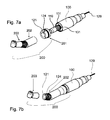
- Fig. 5 respectively Fig. 6 are each shown in a perspective view of the use of the drive device 100 according to the invention together with a medical or dental instrument or handpiece 200. Further detailing, in particular of the instrument or handpiece 200, takes place in FIG Fig. 7a, 7b , The instrument or handpiece 200 has an opening so that it can be pushed onto the coupling 10. With the help of the coupling drive torque, but also media such as light, gas, compressed air, liquids, electricity, energy, etc. are directed to the middle relationship as the head of the handpiece.
- the light-emitting diode 124 is provided in the drive device 100.
- a light guiding system such as optical fibers, starts to pick up the light emitted from the light emitting diode 124 and guide it to the head area.
- Fig. 7a, 7b two variants of the medical or dental instrument or handpiece according to the invention are shown, which carries a light-emitting diode 124 on a carrier device 121.
- the handpiece 200 is subdivided into a foot region 201, which in particular has the media connection to the respective media end channels on the drive device 100.
- a central region 202 which forms the intermediate piece between the foot region 201 and the head region 203, on which the tool or the like is arranged.
- the structure of the carrier 121 is very variable. He is designed, for example, as in the Fig. 3 . 4a to 4c shown.
- Fig. 7a the carrier device 121 is integrated in the foot region 201 and utilizes there the region converging conically in the direction of the head region 203. This results in a very space-saving arrangement.
- Fig. 7a 7b shows the instrument / handpiece 200 subdivided into its respective areas. In fact, this is of course assembled in use or made in one piece or interconnected.
- the carrier unit 121 is provided with the light-emitting diode 124 in the centerpiece 202, whereby a further light-guiding system can already be dispensed with in this embodiment, since in use the middle region likewise enters the oral cavity and thus provides illumination of the working field.
- central region 202 or head region 203 with energy, in particular current (undoubtedly concealed) energy-conducting contacts are provided on the end side of the foot region 201 facing the drive device 100, which are connected to corresponding energy-conducting contacts 131 on the End plate of the drive device 100 cooperate mutatis mutandis.
- corresponding guide lugs and recesses are provided in the mating elements to ensure an angular exact merging of the handpiece or instrument 200 with the drive device 100.
- the light emitter 120 may additionally be provided with optical systems for the light emitting diode 124 itself, assistive reflectors, and / or lenses and / or prisms, to increase the efficiency of the light emitter 120, but not limited thereto be.
- the cover or the cover 125 need not be executed solid, but may be suitable for coordination with a respective appropriate heat transfer recesses and holes or be designed as a suitable guided walls, thereby further advantageously at the same time sufficient heat dissipation, a lower material usage and a lower weight of the drive device can be achieved.
- the use of a high-current LED or power LED already reduces the heat output generated by the light source and thus the heat development of the light-emitting device 120.
- the required cooling can then be done without cooling air holes in a passive manner by providing sufficient or maximum large segment areas and with heat contact surfaces on an upper side or upper side via a thermal interface material (TIM) and / or a lower side or backside over the intermediate heat material on the IMS (Aluong).
- TIM thermal interface material
- a good heat transfer can also be achieved by means of a (not shown) constructive solution using a spring preload in an additional, separate component or, alternatively, the same effect, the elastomeric member 127.
- Significant benefits result in a significant increase in the life of the Lichtabstrahl coupled 120 and the elimination of maintenance costs and interchangeability for an end user.
- Fig. 8a to 8c show in exploded views a further variant of the embodiment of a coupling device with light-emitting device and media connections according to the invention.
- Already presented reference numerals are reused in the same way, as in the previously presented figures.
- an elastomeric disk or plate 127 is provided as means for generating a spring preload on the coupling device 110, which has on one side a medium pipe 140 which is connected there.
- a liquid feed 150 is also provided opposite, which is likewise arranged on the elastomer disk or plate as elastomer element 127.
- the support 122 is again arranged in the features already described.
- the elastomeric element 127 is made to the difference of the previously presented variants of a sterilizable silicone and in particular provided with resilient properties. This makes it possible to provide a sufficient contact pressure in the assembled state generate enough to obtain the desired positive heat dissipation from the light emitting diode or lighting device.
- the embodiment of the elastomeric element 127 provides a seal against attachments made of plastic or steel, which, as already mentioned, can be both the handpiece 200 or its foot 201, center 202 or head region 203. This is from the here shown Fig. 8a to 8c not apparent.
- a media pipe connection 141 is also provided on the side of the elastomer element 127 opposite the media pipe 140.
- a media pipe connection 141 is also provided on the side of the elastomer element 127 opposite the media pipe 140.
- Fig. 8c the same elements are also shown again from another perspective.
Landscapes
- Health & Medical Sciences (AREA)
- Oral & Maxillofacial Surgery (AREA)
- Dentistry (AREA)
- Epidemiology (AREA)
- Life Sciences & Earth Sciences (AREA)
- Animal Behavior & Ethology (AREA)
- General Health & Medical Sciences (AREA)
- Public Health (AREA)
- Veterinary Medicine (AREA)
- Dental Tools And Instruments Or Auxiliary Dental Instruments (AREA)
- Led Device Packages (AREA)
Applications Claiming Priority (1)
| Application Number | Priority Date | Filing Date | Title |
|---|---|---|---|
| DE102008054196A DE102008054196A1 (de) | 2008-10-31 | 2008-10-31 | Lichtabstrahleinrichtung und Antriebsvorrichtung mit einer Leuchtdiode |
Publications (2)
| Publication Number | Publication Date |
|---|---|
| EP2181662A2 true EP2181662A2 (fr) | 2010-05-05 |
| EP2181662A3 EP2181662A3 (fr) | 2012-10-17 |
Family
ID=41666651
Family Applications (1)
| Application Number | Title | Priority Date | Filing Date |
|---|---|---|---|
| EP09013096A Withdrawn EP2181662A3 (fr) | 2008-10-31 | 2009-10-16 | Dispositif de rayonnement lumineux et dispositif d'entraînement doté d'une diode lumineuse |
Country Status (4)
| Country | Link |
|---|---|
| US (1) | US20100112509A1 (fr) |
| EP (1) | EP2181662A3 (fr) |
| JP (1) | JP2010104790A (fr) |
| DE (1) | DE102008054196A1 (fr) |
Cited By (1)
| Publication number | Priority date | Publication date | Assignee | Title |
|---|---|---|---|---|
| CN104456178A (zh) * | 2014-10-22 | 2015-03-25 | 浙江天时光电科技有限公司 | 一种多功能led灯泡 |
Citations (3)
| Publication number | Priority date | Publication date | Assignee | Title |
|---|---|---|---|---|
| DE69816716T2 (de) | 1997-06-09 | 2004-07-15 | Nakanishi Inc., Kanuma | Zahnärtzliches Handstück mit Beleuchtungsmittel |
| DE102004022095A1 (de) | 2003-05-06 | 2005-03-03 | J. Morita Mfg. Corp. | Medizinische Bestrahlungsvorrichtung |
| DE102004061551A1 (de) | 2003-12-30 | 2005-07-28 | Ultradent Products, Inc., South Jordan | Dentale Aushärtungsvorrichtung mit einer Wärmesenke zum Abführen von Wärme |
Family Cites Families (10)
| Publication number | Priority date | Publication date | Assignee | Title |
|---|---|---|---|---|
| US5820373A (en) * | 1995-08-29 | 1998-10-13 | Koichi Okano | Cleaning device for periodontal pocket |
| IT1296089B1 (it) * | 1997-11-10 | 1999-06-09 | Mectron Di Bianchetti Fernando | Manipolo odontoiatrico con sorgente luminosa a scopo diagnostico |
| US20020151941A1 (en) * | 2001-04-16 | 2002-10-17 | Shinichi Okawa | Medical illuminator, and medical apparatus having the medical illuminator |
| US20030036031A1 (en) * | 2001-08-20 | 2003-02-20 | Lieb Joseph Alexander | Light-emitting handpiece for curing photopolymerizable resins |
| US7182597B2 (en) * | 2002-08-08 | 2007-02-27 | Kerr Corporation | Curing light instrument |
| EP1550167B1 (fr) * | 2002-09-30 | 2007-11-28 | Teledyne Lighting and Display Products, Inc. | Ensemble illuminateur |
| JP2007524469A (ja) * | 2003-06-27 | 2007-08-30 | ディスカス デンタル インプレッションズ インコーポレーテッド | 光源を有する超音波歯科器具 |
| US7371066B2 (en) * | 2004-09-15 | 2008-05-13 | Miltex, Inc. | Illuminated dental examination instrument |
| US20080166678A1 (en) * | 2007-01-04 | 2008-07-10 | Or Ramot | Removable intraoral lighting device |
| DE102007040596B4 (de) * | 2007-08-27 | 2011-01-13 | Epsys Paul Voinea E.K. | Beleuchtungsmittel mit Wärmespreizung durch Wärmeleitbeschichtung |
-
2008
- 2008-10-31 DE DE102008054196A patent/DE102008054196A1/de not_active Withdrawn
-
2009
- 2009-10-16 EP EP09013096A patent/EP2181662A3/fr not_active Withdrawn
- 2009-10-30 US US12/588,861 patent/US20100112509A1/en not_active Abandoned
- 2009-10-30 JP JP2009250324A patent/JP2010104790A/ja active Pending
Patent Citations (3)
| Publication number | Priority date | Publication date | Assignee | Title |
|---|---|---|---|---|
| DE69816716T2 (de) | 1997-06-09 | 2004-07-15 | Nakanishi Inc., Kanuma | Zahnärtzliches Handstück mit Beleuchtungsmittel |
| DE102004022095A1 (de) | 2003-05-06 | 2005-03-03 | J. Morita Mfg. Corp. | Medizinische Bestrahlungsvorrichtung |
| DE102004061551A1 (de) | 2003-12-30 | 2005-07-28 | Ultradent Products, Inc., South Jordan | Dentale Aushärtungsvorrichtung mit einer Wärmesenke zum Abführen von Wärme |
Cited By (1)
| Publication number | Priority date | Publication date | Assignee | Title |
|---|---|---|---|---|
| CN104456178A (zh) * | 2014-10-22 | 2015-03-25 | 浙江天时光电科技有限公司 | 一种多功能led灯泡 |
Also Published As
| Publication number | Publication date |
|---|---|
| EP2181662A3 (fr) | 2012-10-17 |
| DE102008054196A1 (de) | 2010-05-06 |
| JP2010104790A (ja) | 2010-05-13 |
| US20100112509A1 (en) | 2010-05-06 |
Similar Documents
| Publication | Publication Date | Title |
|---|---|---|
| EP2311366B1 (fr) | Module d'éclairage à DEL | |
| EP2198196B1 (fr) | Lampe | |
| EP2396590B1 (fr) | Dispositif d'éclairage | |
| EP1995514B1 (fr) | Unité d'éclairage | |
| EP1886643B1 (fr) | Appareil de durcissement à la lumière | |
| DE102007040596B4 (de) | Beleuchtungsmittel mit Wärmespreizung durch Wärmeleitbeschichtung | |
| EP1398005B1 (fr) | Appareil de photopolymérisation | |
| WO2011012437A1 (fr) | Dispositif d'éclairage et procédé de fabrication d'un dispositif d'éclairage | |
| DE102007002838A1 (de) | LED-Modul mit Montagemittel umfassenden Kühlkörpern | |
| EP1228738B1 (fr) | Appareil pour la photopolymérisation avec source de rayonnement par semi-conducteur connectée à un corps de base par thermoconducteur | |
| EP2324284A1 (fr) | Dispositif d'éclairage comportant une diode électroluminescente | |
| WO2013156023A1 (fr) | Ampoule de rattrapage à del | |
| DE102005059198A1 (de) | Flächenleuchte | |
| EP2096685A1 (fr) | Module à DEL doté de corps de refroidissement comprenant un moyen de montage | |
| EP2171352B1 (fr) | Ampoule | |
| EP2181662A2 (fr) | Dispositif de rayonnement lumineux et dispositif d'entraînement doté d'une diode lumineuse | |
| EP1731862B1 (fr) | Source lumineuse pour l'endoscopie et la microscopie | |
| EP1647763A1 (fr) | Lampe pour examen médical ou opération chirurgicale avec une source LED optimisée | |
| DE102017109836B4 (de) | Leuchtmittel mit Kühlkörper | |
| EP3173693B1 (fr) | Appareil d'éclairage comprenant une pluralité d'ampoules à del | |
| EP2305163B1 (fr) | Dispositif d'éclairage pour une pièce à main dentaire | |
| EP1870021B1 (fr) | Pièce à main médicale avec dispositif d'illumination | |
| DE102009045189A1 (de) | Beleuchtungsvorrichtung für ein dentales Handstück | |
| DE202009000002U1 (de) | Baugruppe für eine Hochleistungs-LED-Lampe sowie Chipträger für eine solche Lampe | |
| DE102009003301A1 (de) | Baugruppe für eine Hochleistungs-LED-Lampe sowie Chipträger für eine solche Lampe |
Legal Events
| Date | Code | Title | Description |
|---|---|---|---|
| PUAI | Public reference made under article 153(3) epc to a published international application that has entered the european phase |
Free format text: ORIGINAL CODE: 0009012 |
|
| AK | Designated contracting states |
Kind code of ref document: A2 Designated state(s): AT BE BG CH CY CZ DE DK EE ES FI FR GB GR HR HU IE IS IT LI LT LU LV MC MK MT NL NO PL PT RO SE SI SK SM TR |
|
| AX | Request for extension of the european patent |
Extension state: AL BA RS |
|
| PUAL | Search report despatched |
Free format text: ORIGINAL CODE: 0009013 |
|
| AK | Designated contracting states |
Kind code of ref document: A3 Designated state(s): AT BE BG CH CY CZ DE DK EE ES FI FR GB GR HR HU IE IS IT LI LT LU LV MC MK MT NL NO PL PT RO SE SI SK SM TR |
|
| AX | Request for extension of the european patent |
Extension state: AL BA RS |
|
| RIC1 | Information provided on ipc code assigned before grant |
Ipc: A61C 1/08 20060101AFI20120911BHEP Ipc: A61B 1/24 20060101ALI20120911BHEP |
|
| STAA | Information on the status of an ep patent application or granted ep patent |
Free format text: STATUS: THE APPLICATION IS DEEMED TO BE WITHDRAWN |
|
| 18D | Application deemed to be withdrawn |
Effective date: 20130418 |