EP2181748B1 - Hdrodynamischer separator zur Reinigung eines Fluidstromes - Google Patents
Hdrodynamischer separator zur Reinigung eines Fluidstromes Download PDFInfo
- Publication number
- EP2181748B1 EP2181748B1 EP20090306013 EP09306013A EP2181748B1 EP 2181748 B1 EP2181748 B1 EP 2181748B1 EP 20090306013 EP20090306013 EP 20090306013 EP 09306013 A EP09306013 A EP 09306013A EP 2181748 B1 EP2181748 B1 EP 2181748B1
- Authority
- EP
- European Patent Office
- Prior art keywords
- partition
- grid
- inlet
- effluent
- chamber
- Prior art date
- Legal status (The legal status is an assumption and is not a legal conclusion. Google has not performed a legal analysis and makes no representation as to the accuracy of the status listed.)
- Not-in-force
Links
Images



Classifications
-
- B—PERFORMING OPERATIONS; TRANSPORTING
- B01—PHYSICAL OR CHEMICAL PROCESSES OR APPARATUS IN GENERAL
- B01D—SEPARATION
- B01D39/00—Filtering material for liquid or gaseous fluids
- B01D39/10—Filter screens essentially made of metal
- B01D39/12—Filter screens essentially made of metal of wire gauze; of knitted wire; of expanded metal
-
- E—FIXED CONSTRUCTIONS
- E03—WATER SUPPLY; SEWERAGE
- E03F—SEWERS; CESSPOOLS
- E03F5/00—Sewerage structures
- E03F5/14—Devices for separating liquid or solid substances from sewage, e.g. sand or sludge traps, rakes or grates
Definitions
- the present invention relates to a hydrodynamic separator for separating solids from a vein of charged effluents passing through the apparatus and comprising a partition wall on which the vein of the effluent arrives and separating an inlet chamber, where collected solid waste of given dimensions and an outlet chamber located downstream of the partition wall receiving the cleaned effluent of their solid waste, the partition wall is constituted by a gate, being intended to be traversed by the cleaned effluents, the inlet chamber and outlet chamber being made in a tank and large waste, which can not cross the partition, are collected at the bottom of the inlet chamber.
- a macro-waste separator constituted by a cylindrical structure provided, in the upper part, with a loaded effluent inlet and a cleaned effluent outlet.
- the separator itself is constituted by a cylindrical volume whose lower part is occupied by a basket.
- the charged effluent stream is circulating in this cylindrical volume above the basket, so that macro-waste whose size is greater than that of the mesh of the basket remain retained in the basket; the effluents thus cleaned pass through the basket to pass into the peripheral volume surrounding the basket in the outlet at the bottom of the tank, to go back in the outlet pipe whose height position defines the level of liquid remaining in the separator.
- this separator has the disadvantage of clogging very easily because macro-waste such as plastic bags, bottles, etc., may accumulate against the walls of the grid since the vein of charged effluent only turns in the upper part of the tank.
- the vein of cleaned effluents simply escapes radially through the meshes of the basket without performing at this location, movement movements since the basket can guide this movement. Waste cluttering the walls of the basket reduce the flow of liquid through the basket and, therefore, it reduces the efficiency of the separation since the effluent flow that can not pass through the separator basket will be directly discharged to the outlet by the overflow.
- this expanded sheet metal grid has diamond-shaped openings.
- Such openings facilitate the attachment of the solid elements during the passage of the effluent stream through the grid because the flow on the inclined sides of the openings creates turbulence and repels water and waste in the corners which contributes to seal the openings.
- hydrodynamic effluent separators already exist urban and industrial comprising a casing in which is placed a bottomless cylindrical side grid circular cylindrical whose wall is constituted by an expanded metal grid.
- the effluents arrive inside the basket with an open bottom to rotate, so as to lower by cyclone effect, the heavy and bulky materials loading the effluents at the bottom of the casing, while the separated liquid of these products which load it, can cross the lateral surface of the basket and be evacuated like cleaned effluent.
- the circulation of the effluent stream inside the expanded sheet metal basket makes it possible to avoid, to a certain extent, the deposition of products or particles of a certain size on the grid so as to preserve the entire section. free passage vis-à-vis the effluents.
- this lenticular shape of the openings or punctures of the sheet generates by the deflecting surfaces thus constituted at the nodes, dispersed effluent streams, passing precisely above the nested corners of the lenticular openings which follow one another in the direction of the flow, favoring the stuffing of these corners and, consequently, the progressive obstruction of the openings, very detrimental to the cleaning efficiency.
- This requires frequent interventions in the separator at the risk of seeing the uncleaned effluent, overflow the basket and go directly into the outlet.
- the figure 6 is an enlarged view of such a known known expanded metal partition used in separation techniques large-scale waste stream of charged effluent.
- These fan-shaped openings in the expanded metal sheet are substantially delimited by branches or strips of the same width over the entire surface of the grid.
- the strips are joined by nodes N.
- Each node N is the junction of four branches or strips B1, B2, B3, B4 which constitute the sides of four adjacent openings O1, 02, 03, 04; this pattern is repeated identically over the entire surface of the expanded metal sheet.
- the openings O1, ..., 04 all have a fan shape or curvilinear triangle with vertices SM1, SM2, SM3.
- the shape obtained is very particular and consists in fact of four partial surfaces: two surfaces S1, S2 directly at the exit of the top SM3 and which are directed upwards, then an edge a1 which substantially reaches the opposite peaks SM1, SM2 of two openings O1, 03, to then reach the apex SM3 of the opening 02 next by a curved shape.
- This complex shape of the surface of the node N is also shown schematically by a bundle of four arrows F1-F4 issued from a common point and represented on the top of a following node to show in a simplified manner, the direction of the component surfaces. the node N.
- this surface of the node is the main surface encountered by the effluent stream which licks the separating grid so that this vein undergoes multiple deflections in the direction of passage of the effluent.
- the flow along the surface of the grid does not favor the cleaning of the peaks SM1 and SM2 of the orifices O1, ..., 04 in which large objects can cling to progressively clogging the grid and reducing the passage of cleaned effluents.
- the present invention aims to overcome the disadvantages of known separators and proposes to develop a hydrodynamic separator effective in its cleaning of urban or industrial rainwater effluents, which is easy to achieve and maintain and whose risks of stuffing openings are reduced.
- the particular structure of the expanded metal grid with elongated hexagonal openings makes it possible to generate parallel jets in the vein of fluid flowing against the separation surface, guided by the nodes of large and solid shape between the openings.
- the width of the flat surface is constituted practically by the entirety of the surface of the nodes, since this surface is delimited by the two supports of the tool realizing the cutting of the metal to deploy it in strips, allowing to guide the part of fluid vein at this surface without disturbing it by forming fluid streams, parallel.
- the guide effectively prevents the deposition of macro-debris and large particles in the corners of the hexagonal shaped openings, especially since the elongated hexagonal shape, the angle of openings is relatively important.
- the grid with elongated hexagonal apertures or meshes, as defined above, makes it possible to obtain, compared to the state of the art, a higher percentage of vacuum with respect to the openings or meshes of expanded metal sheets with lenticular openings according to the prior art. the state of the art.
- the grid makes it possible to reduce the pressure losses induced by the crossing of the cleaned effluents (cleaned water) through the openings of the grid and it limits the fouling at the two ends or tops of the openings of the grid.
- the grid increases the processing capacity per unit area and reciprocally can treat the same flow equivalent performance in a more compact work, so more economical.
- the grid also improves the hydraulic operation of the guide surfaces forming baffles in the manner of louvers, to separate the raw effluent relative to the surface of the grid and reduce fouling and clogging phenomena.
- This hydrodynamic separator integrating the overflow into the treatment tank, has the advantage of having small dimensions and still allow good access to the volume of the tank collecting the waste, that is to say the volume in which the effluents loaded upstream of the grid arrive.
- This accessibility is provided by the curved shape of the grid which is only a curve arc for the section of the cylinder constituting the separating partition. This allows to somehow bypass the concave shape, the projection of the access opening made in the tank lid and down a ladder at this location.
- the lower and upper parts of the partition are constituted by solid sheet elements.
- the overflow used to evacuate the excess flow is then disposed in a chamber located upstream of the separator; it is constituted by an oblique threshold whose height is calculated in order to obtain a sufficient flow velocity in front of the grid to avoid clogging.
- This form of hydrodynamic separator makes it possible to treat relatively high flow rates while facilitating access to the tank both for extracting the deposited waste and for human intervention inside it. Access to the tank is possible in each of the two volumes separated by the partition and this through separate access ports made in the lid.
- the shape of the partition makes it possible to preserve and favor the effect of rotating the vein of charged effluents, to favor the separation of macro-waste while avoiding the clogging of the grid.
- the permeability of the grid is thus maintained which is advantageous for maintaining the efficiency of the separation and ensuring the treatment of the nominal flow rate of effluents.
- the entire hydrodynamic separator remains nevertheless very compact because the inlet chamber, the exit chamber and the possible junction chamber are chambers of shallow depth of burial with respect to the upper level of the whole of the installation.
- the separator consists of a circular cylindrical shaped treatment tank, housing in its center a cylindrical portion forming a partition wall composed of a solid lower portion, surmounted by a cylindrical grid made expanded sheet with hexagonal openings whose major axis is vertical, the grid itself being surmounted by a cylindrical upper upper part, and an inlet structure connected to the loaded effluent pipe, this inlet structure being provided with an overflow partition dividing the structure into an inlet volume directing the effluents charged tangentially into the outer chamber of the tank and an outlet volume beyond the overflow partition and in which the untreated effluent passes directly, the stream of charged effluents being rotated in the inlet chamber receiving the charged effluents surrounding the cylindrical outlet chamber receiving the cleaned effluent having passed through the gate, the top of the tank having an access port for accessing the outer chamber surrounding the partition.
- This hydrodynamic separator is characterized by a realization of significant dimensions for the tank in both diameter and height. The accessibility of the tank is also ensured.
- the circulation of the charged effluent stream allows cleaning the grid avoiding clogging and maintaining the perfect transparency of the separator grid with its expanded sheet metal structure with hexagonal openings.
- the volume of waste storage in the separator is much greater than in known separators, which reduces the number of interventions to empty the separator.
- the cylindrical outlet chamber is connected to the outlet of the separator by a siphon pipe.
- the invention relates to a hydrodynamic separator for separating solids from a liquid vein (urban or industrial wastewater effluents) containing waste, particles, macro-debris that must first be separated from this vein of effluents before to treat this vein more finely.
- the hydrodynamic separator consists of a volume defined by a casing provided with an effluent inlet loaded with waste and an effluent outlet cleaned from larger particles.
- the separator is divided into an inlet chamber and an outlet chamber, by a grid for retaining the large particles that are accumulated in front of the grid or at the bottom of the separator.
- the clearance of the grid is in principle ensured by the circulation movement of the effluent stream inside the separator.
- the cleaned effluents pass through the grid and are evacuated through the outlet, without encumbering the grid.
- the grid 1 ( Figure 1A ) is constituted by an expanded metal separating surface, for example made of stainless steel, having hexagonal shaped openings, the long axis GA of which is vertical, the separating surface is installed in the tank vertically according to a preferably circular or curved path, closed on itself or constituted by an arc of a circle or a curve arc such as a spiral.
- the effluent stream EF is directed along the separation surface to induce a circular movement of the vein, during which and as is known, the large size waste, the solid and heavy materials are trained and begin to move. center of this liquid ring in circular motion to descend gradually to the bottom of the separator lower than the grid.
- the EF effluent stream arriving tangentially to the surface of the grid is deflected by guide surfaces placed in front of each orifice of the grid thus creating efficient parallel jets relieving the openings of the grid.
- a mesh of the grid is an opening 10 of hexagonal shape, the major axis GA directed vertically when the grid 1 is installed in the operating position.
- the small axis PA of the opening 10 defines the minimum dimension of the waste that can cross the grid because it corresponds to the distance separating two sides 11.
- the opening 10 is bordered by two long straight sides 11 and two groups of inclined branches 12 which meet at each top and bottom top SH, SB of the elongated hexagon of the opening 10.
- the branches 12 are between them each time an angle ⁇ , relatively open.
- the width (1) of the side 11 is twice the width (l 0 ) of the branches 12. Thanks to the hexagonal shape of the openings 10, the tool used to cut and deploy the sheet makes it possible to obtain flat surfaces for the sides 11 and also for the branches 12 joining the sides 11 by the right folds 13.
- the sides 11 thus form planar guide surfaces ensuring the effective operation of the separator equipped with such a grid according to the invention.
- the meshes are bordered by strips cut into the sheet and forming a zigzag profile, composed of substantially planar segments. These strips meet at the nodes constituting the rectangular guide surfaces 11 planar.
- the strips can be considered as generated by generatrices parallel to a direction of angle ⁇ with respect to the general direction of the deployed sheet.
- the angle ⁇ is an obtuse angle relative to the direction of passage of the effluents on the grid.
- This particular flat shape of the guide surfaces 11 and also parts of the strips 12 between the guide surfaces is obtained by means of this hexagonal shape of the openings 10 bordered by the two long and planar sides 11.
- the figure 1C shows the indications useful for the description of the operation of the separating surface 1 by the shape of the hexagonal openings.
- the direction of passage of the effluent stream on the grid 1 is given by the arrow EF in the plane of the figure 1C and perpendicular to the vertical direction W of installation of the grid and the arrangement of the major axis GA of the openings 10.
- the guide surfaces 11 are horizontal rows R1, R2, R3 on which the effluent stream slips virtually undisturbed, detaching large waste that could hold temporarily.
- more than the angles ⁇ are very open thanks to the hexagonal shape of the openings 10.
- the figure 1D is a sectional or end view of the Figure 1A or 1 C and which shows the arrangement of the guide surfaces 11 and the resulting openings 10.
- the guide surfaces 11 are inclined relative to the manufacturing plane before winding the expanded sheet to form the separating surface placed in the hydrodynamic separator.
- This view shows the alternating deformation of the branches 12 from the same node or guide surface 11 shown hatched. It also shows the openings 10 formed between the strips 12 and the fold lines 13.
- the whole of the separating surface constituted by the grid 1 made of expanded sheet metal is thus in a plane before it is put into generally cylindrical shape of circular or spiral section, corresponding to an entire turn or a fraction of a turn in the separator.
- the figure 2 shows a step of manufacturing a grid 1 expanded sheet in the manufacturing position; the plane of the sheet before its cutting is the horizontal plane represented by the arrow X.
- the direction of attack of the tool is the vertical direction Z.
- the part of the tool which deforms each node realizes the guide surface 11 of a width (in the X direction) equal to twice that of a thong or branch 12.
- the arrows indicate the direction of movement of the straps 12 on the same side of the node 11.
- the strips 12 are deformed downwards and on the upstream side, they deform upwards in the direction indicated by the arrows.
- the angle ⁇ of the nodes with respect to the diagonal D1 of the nodes as shown corresponds to the inclination of the guide surfaces 11 with respect to the base surface or reference surface SR of the expanded sheet once formed and installed next a cylindrical arrangement.
- a first embodiment of the assembly of a hydrodynamic separator will be described below using the Figures 3A-3B-3C .
- This hydrodynamic separator is cyclone type with an integrated overflow.
- the hydrodynamic separator consists of a tank 100 made of concrete, provided with a cover 101 equipped with an access hole 102.
- the charged effluent stream (E1) arrives via an inlet channel 103 provided with a guide member 104 inside the vessel.
- the output of the cleaned effluents is through the channel 105 opening in the upper part of the tank as the supply channel 103.
- the two chambers 110, 120 are separated by a partition 130 of curvilinear shape, part of the height of which is occupied by a grid 132 with hexagonal openings such as that described in FIGS. Figures 1A-2 .
- the solid partition is smooth below and above the grid 132.
- the lower part 131 of the partition goes down to the bottom of the tank 100 whereas the upper part 133, above the gate 132, does not arrive. not completely under cover 101.
- the upper portion 133 is cut to form an overflow partition 134 preceded by a siphoid wall 135, plunging below the normal water level H1 in the tank 100, level defined by the level of the outlet pipe 105.
- This partition 130 without its grid 132 is preferably constituted by a solid sheet metal partition.
- the partition 130 tangentially joins the inner wall of the tank 100, and the vertical partition provided in the upper part of the safety overflow 134, is preceded at this point by the siphoid partition 135.
- the partition 130 separating the two chambers 110, 120 of the separator is composed of a cylindrical first portion 130a in a circular arc, bearing tangentially against the wall of the tank 100 and a second portion 130b substantially radial with the siphoid partition 135.
- the partition 130 reaches the height Hm of the tank just under the cover 101 leaving a slight technical gap; this height is clearly above the outlet level H1 of the tank.
- the first part 130a of the partition is formed of the lower solid part 131, of the grid 132 occupying the middle part between the height H0 and the output level H1, over most of the curved surface, practically on the side of the tank 100 to the second part 130b of the partition as shown in FIG. figure 3C .
- the second part 130b of the partition is formed of the lower solid part, going up to the height H2 of the overflow 134 forming an overflow opening.
- This opening is protected upstream by the siphoid wall 135 plunging to the height P1 in the tank 100 under the H1 level forming in the lower part, a siphon inlet.
- the effluent passes over the weir of the overflow 134 by taking the path in the siphon along the curvilinear arrow F100 to pass directly. in the output channel 105.
- the inlet baffle 104 directs the effluent stream according to the arrows (F101, F102) ( figure 3B ) along the wall of the tank.
- the fluid stream is then taken up by the partition 130 in the form of a circular cylinder.
- the input volume 110 thus defined does not substantially overlap the access port 102 and appears in dotted lines in the view of the figure 3B .
- This representation is made to show that the projection of the access port 102 of the cover is located in the input volume of the separator and provides easy access to this input volume.
- This arrangement facilitates the installation of a pumping pipe at the bottom of the tank for the recovery of deposited waste and also the access of a person.
- the access port 102 opens into this sufficiently large volume because delimited by the concave shape of the deflector and allows to have a sufficient access volume for maintenance work.
- FIGS. 4A and 4B show, in vertical section and in horizontal section, another embodiment of a hydrodynamic separator with external overflow.
- This separator consists of a treatment tank 200, of cylindrical shape and preferably of circular section, made of concrete comprising a partition wall 230 with an inlet chamber 210 receiving the charged effluents and an outlet chamber 120 collecting the cleaned effluents to evacuate them.
- the inlet of the tank is made from a catch or weir structure 240 connected to the effluent line to be treated 241.
- This weir 240 is a structure divided into an inlet volume 242 and an outlet volume 243. by a partition 244 on a portion of the height of the structure so as to normally direct the vein of effluents loaded into the treatment tank 200 and allow, in case of too much flow, the excess to pass over the partition 244 and go directly to the exit.
- the inlet volume 242 of this weir 240 communicates with the treatment tank 200 via a non-radial but tangential passage 245, directed along the partition 230.
- This partition 230 is constituted by a lower portion 231, an average of which there is the separation grid 232 and, above it, an upper portion 233.
- the portion 230 has a semi-circular cylindrical shape with continuity of the lower portion 231, the gate 232 and the upper portion 233 along the curved path substantially tangentially joining the channel formed by the partition 244 of the spillway 240 which directs the fluid stream tangentially on the partition 230.
- the other side of the partition 230 joins the inner side of the treatment vessel 200 by a substantially radial partition 206 which represents a recess.
- This recess may receive a scale permanently fixed in the tank, near the access port 202. As the loaded effluent stream describes a circular path, it will not sweep this substantially radial surface 206 and the large waste. dimensions will not be likely to cling to the rungs of the ladder.
- the effluent stream thus generates a rotational movement along the solid portion 233 of the partition to descend at the gate 232 by licking this gate as in the other embodiments.
- the heavy or bulky waste is detached from the gate 232 and gradually descend to the bottom of the tank 200, below the gate 232 in what is a large waste storage volume.
- the cleaned effluent can pass through the separation grid 232 to reach the outlet chamber 220 which communicates with the outlet port 250 to which is also connected the volume 243 of the weir 240, downstream of its inlet volume 242.
- the plan view of the Figure 4B shows, in broken lines, the possible position of the access ports 202 of the cover. These access ports allow easy access to the inlet chamber 210 or the outlet chamber 220 in the vessel 200 of the separator.
- This hydrodynamic separator of large dimensions connects the outlet 205 of the treatment tank to the treated water discharge structure 250 via a junction view 260.
- the connection could also be made directly.
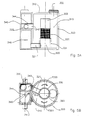
- FIGS. 5A, 5B show another embodiment of a hydrodynamic separator with an external overflow.
- This separator consists of a cylindrical treatment tank 300 of circular section provided with a separation partition 330 of circular cylindrical shape receiving on a bottom portion 331 full, the separation grid 332 of circular cylindrical shape itself surmounted by part of solid partition 333, circular cylindrical.
- This assembly consisting of the lower part 331, the gate 332 and the upper part 333 divides the treatment tank 300 into an inlet chamber 310 receiving the external effluent loaded and an outlet chamber 320 in which arrive the cleaned effluent.
- the inner chamber 320 is connected to the outlet by a 321 duct leaving in the low position of the chamber receiving the treated water having passed through the gate 332, this pipe 321 forms an outlet siphon preventing the light liquids having passed through the gate can pass into the outlet.
- This pipe 321 opens, in the lower part, into the chamber 349 which rises towards the exit 350.
- the vein of charged effluents arrives through the inlet pipe 341 in an inlet weir 340, to arrive tangentially as shown in FIG. Figure 5B in the tank 300 and circulate in the direction of the two arrows F301, F302 in the outer chamber 310.
- the effluent stream detaches any waste hung on the outer surface of the gate 332 to allow effluent cleaned macro waste, to cross the gate and pass into the inner volume 320 and then be extracted through the outlet pipe.
- the inlet weir also comprises an overflow 344 which, under normal flow conditions, feeds the tank 300 but which, in the event of a high inflow, allows a portion of this flow to pass over the bulkhead. overflow 344 to get directly to the exit.
- This hydrodynamic separator is a large separator, for example a tank a few meters in diameter and a height also a few meters.
- the access port 302 provided in the lid 301 of the tank 300 allows easy access to the external volume 310 and also to the gate 332 by rotating around the gate 332 in the external volume.
- the charged effluent stream circulates inside the gate, in this embodiment, the circulation is outside.
Landscapes
- Engineering & Computer Science (AREA)
- Textile Engineering (AREA)
- Chemical & Material Sciences (AREA)
- Chemical Kinetics & Catalysis (AREA)
- Health & Medical Sciences (AREA)
- Life Sciences & Earth Sciences (AREA)
- Hydrology & Water Resources (AREA)
- Public Health (AREA)
- Water Supply & Treatment (AREA)
- Paper (AREA)
- Separating Particles In Gases By Inertia (AREA)
- Cyclones (AREA)
Claims (6)
- Hydrodynamischer Separator zum Abscheiden von Feststoffen aus einem belasteten Abwasserstrom, der durch die Vorrichtung strömt, enthaltend einen Behälter mit einer Einlasskammer und einer Auslasskammer, die durch eine Zwischenwand getrennt sind, die aus einem Gitter besteht, das dazu bestimmt ist, von dem Abwasser durchströmt zu werden und auf das der Abwasserstrom tangential auftrifft,
wobei die Einlasskammer die festen Abfallstoffe mit bestimmten Abmessungen abfängt und die stromabwärts der Trennzwischenwand gelegene Auslasskammer das von seinen festen Abfallstoffen gereinigte Abwasser aufnimmt,
welcher Separator dadurch gekennzeichnet, dass- das Gitter (1) der Trennzwischenwand (130) zwischen der Einlasskammer (110) und der Auslasskammer (120) des Behälters aus einem Blech aus Streckmetall besteht, dessen Öffnungen (10) eine längliche Sechseckform haben, die von Bändern aus Streckmetall begrenzt wird, wobei diese Bänder aus ebenen Flächen bestehen, die von parallel verlaufenden Mantellinien gebildet werden, die einen stumpfen Winkel bezüglich der Gesamtfläche des Gitters (1) einschließen,- wobei die sechseckförmigen länglichen Öffnungen (10) von Metallbändern umrandet sind, die in Richtung der Länge der Öffnungen die Seiten (11) bilden, sowie von Metallbändern, welche die Schenkel (12) bilden, die auf die beiden Scheitelpunkte (SH, SB) der sechseckförmigen Öffnungen treffen und über Biegelinien (13) auf diese treffen,- wobei die ebenen Seiten (11) eine Breite haben, die gleich der zweifachen Breite der Schenkel (11) ist,- wobei die Öffnungen (10) eine Hauptachse (GA) haben, die senkrecht zur Richtung der Nebenachse (PA) verläuft, welche der Richtung (EF) des belasteten Abwasserstroms entspricht, der entlang des Gitters (1) strömt, wenn dieses im hydrodynamischen Separator verbaut ist. - Hydrodynamischer Separator nach Anspruch 1,
dadurch gekennzeichnet, dass
der im Querschnitt kreisförmige, zylindrische Behälter (100), der die Einlasskammer (110) und die Auslasskammer (120) enthält, ein Innenvolumen aufweist, das von der Trennzwischenwand (130) in Einlasskammer (110) und Auslasskammer (120) unterteilt wird, wobei die in die Einlasskammer mündende Einlassleitung (103) und die Auslassleitung (105) für das gereinigte Abwasser von der Auslasskammer (120) ausgehen,
wobei die Zwischenwand (130) aus einem massiv ausgeführten unteren Teil (131), einem Mittelteil (132), das aus einem Gitter aus Streckmetall mit sechseckförmigen Öffnungen mit in senkrechter Richtung gerichteter Hauptachse (GA) besteht, und aus einem oberen Wandteil (133) gebildet ist und praktisch die gesamte Höhe des Innenraums des Behälters verschließt,
wobei diese Zwischenwand (130) mit tangential verlaufendem Kontakt auf die Behälterwand trifft und dabei mit einem kurvenförmigen, insbesondere kreisbogenförmigen Verlauf angeordnet ist, um am anderen Ende auf einen radial verlaufenden Zwischenwandabschnitt zu treffen, der einen Überlauf (134) bildet, der von einer siphonförmigen Wand (135) abgeschirmt wird, welche das direkte Abführen von einem Überlauf aufgrund einer übermäßigen Durchflussmenge von Abwasser am Einlass gestattet,
wobei die Zwischenwand einen konvexen Verlauf hat, so dass praktisch der Mittelbereich des Behälters freigelassen wird, der von einer Zugangsöffnung (102) überhöht wird, um Betrieb und Wartung zu gestatten. - Hydrodynamischer Separator nach Anspruch 2,
dadurch gekennzeichnet, dass
der untere (131) und der obere Teil (133) der Zwischenwand sowie der Überlauf (134) und die siphonförmige Zwischenwand (135) aus Elementen aus massivem Blech bestehen. - Hydrodynamischer Separator nach Anspruch 1,
dadurch gekennzeichnet, dass- der im Querschnitt kreisförmige, zylindrische Behälter (200) mit einem äußeren Anbauteil (240) versehen ist, welches einen Ablauf bildet, am Einlass (245) des Behälters montiert und mit der Zulaufleitung (241) für belastetes Abwasser verbunden ist, wobei der Behälter (200) in Einlasskammer (210) für belastetes Abwasser und in Auslasskammer (220) für gereinigtes Abwasser durch die Zwischenwand (230) aufgeteilt ist, welche zylinderförmig ist und einen im wesentlichen halbkreisförmigen Querschnitt hat und einen massiv ausgeführten unteren Abschnitt (231), der von einem Gitter (233) aus Streckmetall mit sechseckförmigen Öffnungen mit vertikal verlaufender Hauptachse überhöht wird, und einen massiv ausgeführten oberen Abschnitt (233) enthält,- wobei die Zwischenwand (230), die auf die Innenseite des Behälters (200) trifft, eine radial verlaufende Zwischenwand (206) ist,- wobei das Einlassgehäuse (240) eine Überlaufzwischenwand (244) aufweist, über welche der Einlassstrom zur Einlassöffnung (245) des Behälters (200) geleitet wird, um den Abwasserstrom tangential auf die obere Zwischenwand (233) zu leiten, damit dieser in Drehung versetzt wird und drehend auf der Innenseite des Gitters (232) abfließt,- wobei diese Überlaufzwischenwand (244) eine übermäßige Durchflussmenge der Einlassleitung (241) zum Auslassschacht (250) hin unmittelbar durchlaufen lässt, ohne durch den Behälter (200) des hydrodynamischen Separators zu treten,- wobei der Auslass (205) der Kammer (220) für gereinigtes Abwasser auch mit dem Auslassschaft (250) verbunden ist. - Hydrodynamischer Separator nach Anspruch 1,
dadurch gekennzeichnet, dass
er aus einem Behandlungsbehälter (300) mit kreiszylindrischer Form besteht, der in seinem Zentrum einen Zylinderabschnitt aufnimmt, welcher eine Trennzwischenwand bildet, die aus einem massiv ausgeführten unteren Teil (331) besteht, der von einem zylinderförmigen Gitter (332) aus Streckmetall mit sechseckförmigen Öffnungen mit vertikal verlaufender Hauptachse überhöht wird, wobei das Gitter (332) seinerseits von einem massiv ausgeführten, zylindrischen oberen Teil (333) überhöht wird, und sowie aus- einem Einlassanbauteil (340), das mit der Leitung für belastetes Abwasser (341) verbunden ist, wobei dieses Einlassanbauteil mit einer Überlaufzwischenwand (344) versehen ist, welche das Anbauteil (340) in einen Einlassraum, welcher das belastete Abwasser tangential in die äußere Kammer (310) des Behälters (300) leitet, und in einen Auslassraum jenseits der Überlaufzwischenwand (344) unterteilt, in welchen das belastete Abwasser unmittelbar strömt,wobei der belastete Abwasserstrom mit einer Drehbewegung (F300) in die Einlasskammer geleitet wird, welche das belastete Abwasser (310) aufnimmt, das die zylindrische Auslasskammer umgibt, welche das gereinigte Abwasser (320) aufnimmt, welches das Gitter (332) durchströmt hat,
wobei die Oberseite (301) des Behälters (300) eine Zugangsöffnung (302) aufweist, die den Zugang in die äußere Kammer (310) gestattet, welche die Zwischenwand (330) umgibt. - Hydrodynamischer Separator nach Anspruch 5,
dadurch gekennzeichnet, dass
die zylindrische Auslasskammer (320) über eine siphonartige Leitung (321) mit dem Auslass (350) des Separators verbunden ist.
Applications Claiming Priority (1)
| Application Number | Priority Date | Filing Date | Title |
|---|---|---|---|
| FR0857367A FR2937565B1 (fr) | 2008-10-29 | 2008-10-29 | Separateur hydrodynamique pour nettoyer une veine de fluide |
Publications (3)
| Publication Number | Publication Date |
|---|---|
| EP2181748A2 EP2181748A2 (de) | 2010-05-05 |
| EP2181748A3 EP2181748A3 (de) | 2010-05-12 |
| EP2181748B1 true EP2181748B1 (de) | 2013-07-24 |
Family
ID=40984686
Family Applications (1)
| Application Number | Title | Priority Date | Filing Date |
|---|---|---|---|
| EP20090306013 Not-in-force EP2181748B1 (de) | 2008-10-29 | 2009-10-27 | Hdrodynamischer separator zur Reinigung eines Fluidstromes |
Country Status (2)
| Country | Link |
|---|---|
| EP (1) | EP2181748B1 (de) |
| FR (1) | FR2937565B1 (de) |
Cited By (1)
| Publication number | Priority date | Publication date | Assignee | Title |
|---|---|---|---|---|
| US10710907B2 (en) | 2018-01-10 | 2020-07-14 | Hydroworks, Llc | Hydrodynamic separators, assemblies and methods for storm water treatment |
Families Citing this family (1)
| Publication number | Priority date | Publication date | Assignee | Title |
|---|---|---|---|---|
| CN103857856B (zh) | 2011-08-19 | 2016-09-21 | 约尔格-米夏埃尔·施泰因哈特 | 具有高流量旁路的流体流液力分离器 |
Family Cites Families (5)
| Publication number | Priority date | Publication date | Assignee | Title |
|---|---|---|---|---|
| US4883509A (en) * | 1988-02-12 | 1989-11-28 | Giambattista Giusti | Multi stage gas inlet construction for dust collectors |
| AUPO762497A0 (en) * | 1997-06-26 | 1997-07-24 | Cds Pty Ltd | Apparatus and methods for separating solids from flowing liquids or gases |
| AUPP048197A0 (en) * | 1997-11-21 | 1997-12-18 | University Of South Australia | Stormwater filtration apparatus |
| US6156444A (en) * | 1998-12-24 | 2000-12-05 | Precision Combustion, Inc. | Structure for and method of manufacturing aerodynamic expanded metal |
| EP1824576A4 (de) * | 2004-12-17 | 2009-04-29 | Contech Stormwater Solutions I | Vorrichtung zur trennung von partikeln aus einem flüssigkeitsstrom |
-
2008
- 2008-10-29 FR FR0857367A patent/FR2937565B1/fr not_active Expired - Fee Related
-
2009
- 2009-10-27 EP EP20090306013 patent/EP2181748B1/de not_active Not-in-force
Cited By (1)
| Publication number | Priority date | Publication date | Assignee | Title |
|---|---|---|---|---|
| US10710907B2 (en) | 2018-01-10 | 2020-07-14 | Hydroworks, Llc | Hydrodynamic separators, assemblies and methods for storm water treatment |
Also Published As
| Publication number | Publication date |
|---|---|
| EP2181748A2 (de) | 2010-05-05 |
| FR2937565B1 (fr) | 2011-07-29 |
| EP2181748A3 (de) | 2010-05-12 |
| FR2937565A1 (fr) | 2010-04-30 |
Similar Documents
| Publication | Publication Date | Title |
|---|---|---|
| EP2554231B1 (de) | Sieb mit zylindrischem Filterpaneel für Wasserentnahmestelle | |
| JP5679365B2 (ja) | 移送システム | |
| EP3060731B1 (de) | Poolreiniger mit abnehmbarer filtrationsvorrichtung | |
| JP2014024055A5 (de) | ||
| FR2609644A1 (fr) | Filtre auto-nettoyant a inserer sur une conduite sous pression | |
| JP5047851B2 (ja) | 浮遊夾雑物回収装置 | |
| CA2362500C (fr) | Procede et moyens pour la filtration de la pate a papier | |
| JP6408076B2 (ja) | 移送システム | |
| FR2989596A1 (fr) | Appareil nettoyeur de surface immergee a filtration centripete | |
| EP1907091B1 (de) | Schwerkraft-trennvorrichtung zur wasserbehandlung | |
| EP1663438B2 (de) | Lamellendekantiermodul mit vertikalen platten | |
| CN102416274A (zh) | 从流经通道的液体中去除筛屑的设备 | |
| EP2181748A2 (de) | Hydrodynamischer Separator zur Reinigung eines Fluidstromes | |
| FR2871820A1 (fr) | Tamis a panneau filtrant circulaire pour prise d'eau | |
| EP0933110A1 (de) | Vorrichtung zur Klärung einer durch Flotation beladenen Flüssigkeit | |
| EP0353154B1 (de) | Vorrichtung zum Abscheiden von abgeriebenen Reinigungskugeln aus Rohrbündeln | |
| FR2594044A1 (fr) | Filtre auto-nettoyant. | |
| FR2594045A1 (fr) | Filtre auto-nettoyant, et boite a eau d'entree de condenseur de vapeur comportant un tel filtre. | |
| EP0740955A1 (de) | Behälter mit verbessertem Abzug von Feststoffpartikeln | |
| CA2044520A1 (fr) | Dispositif d'evacuation de l'eau de lavage des filtres a materiau granulaire laves simultanement a l'eau et a l'air. | |
| FR2483799A1 (fr) | Procede et dispositif pour la separation par decantation de matieres solides en suspension dans un liquide | |
| FR2774924A1 (fr) | Separateur pour melange triphasique destine a etre utilise sous le niveau de la mer | |
| FR2960161A1 (fr) | Dispositif de tamisage pour alimentation en eau d'une installation industrielle | |
| FR2907022A1 (fr) | Unite de traitement modulaire | |
| EP1484095B1 (de) | Absetzbecken zur Behandlung von Abflüssen |
Legal Events
| Date | Code | Title | Description |
|---|---|---|---|
| PUAI | Public reference made under article 153(3) epc to a published international application that has entered the european phase |
Free format text: ORIGINAL CODE: 0009012 |
|
| PUAL | Search report despatched |
Free format text: ORIGINAL CODE: 0009013 |
|
| AK | Designated contracting states |
Kind code of ref document: A2 Designated state(s): AT BE BG CH CY CZ DE DK EE ES FI FR GB GR HR HU IE IS IT LI LT LU LV MC MK MT NL NO PL PT RO SE SI SK SM TR |
|
| AX | Request for extension of the european patent |
Extension state: AL BA RS |
|
| AK | Designated contracting states |
Kind code of ref document: A3 Designated state(s): AT BE BG CH CY CZ DE DK EE ES FI FR GB GR HR HU IE IS IT LI LT LU LV MC MK MT NL NO PL PT RO SE SI SK SM TR |
|
| AX | Request for extension of the european patent |
Extension state: AL BA RS |
|
| 17P | Request for examination filed |
Effective date: 20100630 |
|
| GRAP | Despatch of communication of intention to grant a patent |
Free format text: ORIGINAL CODE: EPIDOSNIGR1 |
|
| INTG | Intention to grant announced |
Effective date: 20130502 |
|
| GRAS | Grant fee paid |
Free format text: ORIGINAL CODE: EPIDOSNIGR3 |
|
| GRAA | (expected) grant |
Free format text: ORIGINAL CODE: 0009210 |
|
| AK | Designated contracting states |
Kind code of ref document: B1 Designated state(s): AT BE BG CH CY CZ DE DK EE ES FI FR GB GR HR HU IE IS IT LI LT LU LV MC MK MT NL NO PL PT RO SE SI SK SM TR |
|
| REG | Reference to a national code |
Ref country code: GB Ref legal event code: FG4D Free format text: NOT ENGLISH |
|
| REG | Reference to a national code |
Ref country code: CH Ref legal event code: EP |
|
| REG | Reference to a national code |
Ref country code: AT Ref legal event code: REF Ref document number: 623063 Country of ref document: AT Kind code of ref document: T Effective date: 20130815 |
|
| REG | Reference to a national code |
Ref country code: IE Ref legal event code: FG4D Free format text: LANGUAGE OF EP DOCUMENT: FRENCH |
|
| REG | Reference to a national code |
Ref country code: DE Ref legal event code: R096 Ref document number: 602009017389 Country of ref document: DE Effective date: 20130926 |
|
| REG | Reference to a national code |
Ref country code: AT Ref legal event code: MK05 Ref document number: 623063 Country of ref document: AT Kind code of ref document: T Effective date: 20130724 |
|
| REG | Reference to a national code |
Ref country code: NL Ref legal event code: VDEP Effective date: 20130724 |
|
| REG | Reference to a national code |
Ref country code: LT Ref legal event code: MG4D |
|
| PG25 | Lapsed in a contracting state [announced via postgrant information from national office to epo] |
Ref country code: AT Free format text: LAPSE BECAUSE OF FAILURE TO SUBMIT A TRANSLATION OF THE DESCRIPTION OR TO PAY THE FEE WITHIN THE PRESCRIBED TIME-LIMIT Effective date: 20130724 Ref country code: PT Free format text: LAPSE BECAUSE OF FAILURE TO SUBMIT A TRANSLATION OF THE DESCRIPTION OR TO PAY THE FEE WITHIN THE PRESCRIBED TIME-LIMIT Effective date: 20131125 Ref country code: CY Free format text: LAPSE BECAUSE OF FAILURE TO SUBMIT A TRANSLATION OF THE DESCRIPTION OR TO PAY THE FEE WITHIN THE PRESCRIBED TIME-LIMIT Effective date: 20130828 Ref country code: NO Free format text: LAPSE BECAUSE OF FAILURE TO SUBMIT A TRANSLATION OF THE DESCRIPTION OR TO PAY THE FEE WITHIN THE PRESCRIBED TIME-LIMIT Effective date: 20131024 Ref country code: HR Free format text: LAPSE BECAUSE OF FAILURE TO SUBMIT A TRANSLATION OF THE DESCRIPTION OR TO PAY THE FEE WITHIN THE PRESCRIBED TIME-LIMIT Effective date: 20130724 Ref country code: SE Free format text: LAPSE BECAUSE OF FAILURE TO SUBMIT A TRANSLATION OF THE DESCRIPTION OR TO PAY THE FEE WITHIN THE PRESCRIBED TIME-LIMIT Effective date: 20130724 Ref country code: LT Free format text: LAPSE BECAUSE OF FAILURE TO SUBMIT A TRANSLATION OF THE DESCRIPTION OR TO PAY THE FEE WITHIN THE PRESCRIBED TIME-LIMIT Effective date: 20130724 Ref country code: IS Free format text: LAPSE BECAUSE OF FAILURE TO SUBMIT A TRANSLATION OF THE DESCRIPTION OR TO PAY THE FEE WITHIN THE PRESCRIBED TIME-LIMIT Effective date: 20131124 |
|
| PG25 | Lapsed in a contracting state [announced via postgrant information from national office to epo] |
Ref country code: LV Free format text: LAPSE BECAUSE OF FAILURE TO SUBMIT A TRANSLATION OF THE DESCRIPTION OR TO PAY THE FEE WITHIN THE PRESCRIBED TIME-LIMIT Effective date: 20130724 Ref country code: NL Free format text: LAPSE BECAUSE OF FAILURE TO SUBMIT A TRANSLATION OF THE DESCRIPTION OR TO PAY THE FEE WITHIN THE PRESCRIBED TIME-LIMIT Effective date: 20130724 Ref country code: SI Free format text: LAPSE BECAUSE OF FAILURE TO SUBMIT A TRANSLATION OF THE DESCRIPTION OR TO PAY THE FEE WITHIN THE PRESCRIBED TIME-LIMIT Effective date: 20130724 Ref country code: GR Free format text: LAPSE BECAUSE OF FAILURE TO SUBMIT A TRANSLATION OF THE DESCRIPTION OR TO PAY THE FEE WITHIN THE PRESCRIBED TIME-LIMIT Effective date: 20131025 Ref country code: PL Free format text: LAPSE BECAUSE OF FAILURE TO SUBMIT A TRANSLATION OF THE DESCRIPTION OR TO PAY THE FEE WITHIN THE PRESCRIBED TIME-LIMIT Effective date: 20130724 Ref country code: FI Free format text: LAPSE BECAUSE OF FAILURE TO SUBMIT A TRANSLATION OF THE DESCRIPTION OR TO PAY THE FEE WITHIN THE PRESCRIBED TIME-LIMIT Effective date: 20130724 |
|
| PG25 | Lapsed in a contracting state [announced via postgrant information from national office to epo] |
Ref country code: CY Free format text: LAPSE BECAUSE OF FAILURE TO SUBMIT A TRANSLATION OF THE DESCRIPTION OR TO PAY THE FEE WITHIN THE PRESCRIBED TIME-LIMIT Effective date: 20130724 |
|
| BERE | Be: lapsed |
Owner name: HYDROCONCEPT Effective date: 20131031 |
|
| PG25 | Lapsed in a contracting state [announced via postgrant information from national office to epo] |
Ref country code: DK Free format text: LAPSE BECAUSE OF FAILURE TO SUBMIT A TRANSLATION OF THE DESCRIPTION OR TO PAY THE FEE WITHIN THE PRESCRIBED TIME-LIMIT Effective date: 20130724 Ref country code: RO Free format text: LAPSE BECAUSE OF FAILURE TO SUBMIT A TRANSLATION OF THE DESCRIPTION OR TO PAY THE FEE WITHIN THE PRESCRIBED TIME-LIMIT Effective date: 20130724 Ref country code: SK Free format text: LAPSE BECAUSE OF FAILURE TO SUBMIT A TRANSLATION OF THE DESCRIPTION OR TO PAY THE FEE WITHIN THE PRESCRIBED TIME-LIMIT Effective date: 20130724 Ref country code: EE Free format text: LAPSE BECAUSE OF FAILURE TO SUBMIT A TRANSLATION OF THE DESCRIPTION OR TO PAY THE FEE WITHIN THE PRESCRIBED TIME-LIMIT Effective date: 20130724 Ref country code: CZ Free format text: LAPSE BECAUSE OF FAILURE TO SUBMIT A TRANSLATION OF THE DESCRIPTION OR TO PAY THE FEE WITHIN THE PRESCRIBED TIME-LIMIT Effective date: 20130724 |
|
| PG25 | Lapsed in a contracting state [announced via postgrant information from national office to epo] |
Ref country code: ES Free format text: LAPSE BECAUSE OF FAILURE TO SUBMIT A TRANSLATION OF THE DESCRIPTION OR TO PAY THE FEE WITHIN THE PRESCRIBED TIME-LIMIT Effective date: 20130724 Ref country code: IT Free format text: LAPSE BECAUSE OF FAILURE TO SUBMIT A TRANSLATION OF THE DESCRIPTION OR TO PAY THE FEE WITHIN THE PRESCRIBED TIME-LIMIT Effective date: 20130724 Ref country code: MC Free format text: LAPSE BECAUSE OF FAILURE TO SUBMIT A TRANSLATION OF THE DESCRIPTION OR TO PAY THE FEE WITHIN THE PRESCRIBED TIME-LIMIT Effective date: 20130724 |
|
| PLBE | No opposition filed within time limit |
Free format text: ORIGINAL CODE: 0009261 |
|
| REG | Reference to a national code |
Ref country code: CH Ref legal event code: PL |
|
| STAA | Information on the status of an ep patent application or granted ep patent |
Free format text: STATUS: NO OPPOSITION FILED WITHIN TIME LIMIT |
|
| 26N | No opposition filed |
Effective date: 20140425 |
|
| REG | Reference to a national code |
Ref country code: IE Ref legal event code: MM4A |
|
| PG25 | Lapsed in a contracting state [announced via postgrant information from national office to epo] |
Ref country code: CH Free format text: LAPSE BECAUSE OF NON-PAYMENT OF DUE FEES Effective date: 20131031 Ref country code: LI Free format text: LAPSE BECAUSE OF NON-PAYMENT OF DUE FEES Effective date: 20131031 |
|
| REG | Reference to a national code |
Ref country code: FR Ref legal event code: ST Effective date: 20140630 |
|
| REG | Reference to a national code |
Ref country code: DE Ref legal event code: R097 Ref document number: 602009017389 Country of ref document: DE Effective date: 20140425 |
|
| PG25 | Lapsed in a contracting state [announced via postgrant information from national office to epo] |
Ref country code: FR Free format text: LAPSE BECAUSE OF NON-PAYMENT OF DUE FEES Effective date: 20131031 |
|
| PG25 | Lapsed in a contracting state [announced via postgrant information from national office to epo] |
Ref country code: BE Free format text: LAPSE BECAUSE OF NON-PAYMENT OF DUE FEES Effective date: 20131031 |
|
| PG25 | Lapsed in a contracting state [announced via postgrant information from national office to epo] |
Ref country code: IE Free format text: LAPSE BECAUSE OF NON-PAYMENT OF DUE FEES Effective date: 20131027 |
|
| PG25 | Lapsed in a contracting state [announced via postgrant information from national office to epo] |
Ref country code: SM Free format text: LAPSE BECAUSE OF FAILURE TO SUBMIT A TRANSLATION OF THE DESCRIPTION OR TO PAY THE FEE WITHIN THE PRESCRIBED TIME-LIMIT Effective date: 20130724 |
|
| PG25 | Lapsed in a contracting state [announced via postgrant information from national office to epo] |
Ref country code: TR Free format text: LAPSE BECAUSE OF FAILURE TO SUBMIT A TRANSLATION OF THE DESCRIPTION OR TO PAY THE FEE WITHIN THE PRESCRIBED TIME-LIMIT Effective date: 20130724 |
|
| PG25 | Lapsed in a contracting state [announced via postgrant information from national office to epo] |
Ref country code: BG Free format text: LAPSE BECAUSE OF FAILURE TO SUBMIT A TRANSLATION OF THE DESCRIPTION OR TO PAY THE FEE WITHIN THE PRESCRIBED TIME-LIMIT Effective date: 20130724 Ref country code: MK Free format text: LAPSE BECAUSE OF FAILURE TO SUBMIT A TRANSLATION OF THE DESCRIPTION OR TO PAY THE FEE WITHIN THE PRESCRIBED TIME-LIMIT Effective date: 20130724 Ref country code: HU Free format text: LAPSE BECAUSE OF FAILURE TO SUBMIT A TRANSLATION OF THE DESCRIPTION OR TO PAY THE FEE WITHIN THE PRESCRIBED TIME-LIMIT; INVALID AB INITIO Effective date: 20091027 Ref country code: LU Free format text: LAPSE BECAUSE OF NON-PAYMENT OF DUE FEES Effective date: 20131027 |
|
| PG25 | Lapsed in a contracting state [announced via postgrant information from national office to epo] |
Ref country code: MT Free format text: LAPSE BECAUSE OF FAILURE TO SUBMIT A TRANSLATION OF THE DESCRIPTION OR TO PAY THE FEE WITHIN THE PRESCRIBED TIME-LIMIT Effective date: 20130724 |
|
| REG | Reference to a national code |
Ref country code: DE Ref legal event code: R082 Ref document number: 602009017389 Country of ref document: DE Representative=s name: PATENTANWAELTE STURM WEILNAU FRANKE PARTNERSCH, DE Ref country code: DE Ref legal event code: R082 Ref document number: 602009017389 Country of ref document: DE Representative=s name: QUERMANN STURM WEILNAU PATENTANWAELTE PARTNERS, DE Ref country code: DE Ref legal event code: R081 Ref document number: 602009017389 Country of ref document: DE Owner name: STEINHARDT GMBH, DE Free format text: FORMER OWNER: HYDROCONCEPT, TRAPPES, FR |
|
| REG | Reference to a national code |
Ref country code: GB Ref legal event code: 732E Free format text: REGISTERED BETWEEN 20180308 AND 20180314 |
|
| P01 | Opt-out of the competence of the unified patent court (upc) registered |
Effective date: 20230519 |
|
| PGFP | Annual fee paid to national office [announced via postgrant information from national office to epo] |
Ref country code: GB Payment date: 20231020 Year of fee payment: 15 |
|
| PGFP | Annual fee paid to national office [announced via postgrant information from national office to epo] |
Ref country code: DE Payment date: 20231110 Year of fee payment: 15 |
|
| REG | Reference to a national code |
Ref country code: DE Ref legal event code: R119 Ref document number: 602009017389 Country of ref document: DE |
|
| GBPC | Gb: european patent ceased through non-payment of renewal fee |
Effective date: 20241027 |
|
| PG25 | Lapsed in a contracting state [announced via postgrant information from national office to epo] |
Ref country code: DE Free format text: LAPSE BECAUSE OF NON-PAYMENT OF DUE FEES Effective date: 20250501 |
|
| PG25 | Lapsed in a contracting state [announced via postgrant information from national office to epo] |
Ref country code: GB Free format text: LAPSE BECAUSE OF NON-PAYMENT OF DUE FEES Effective date: 20241027 |