EP2554231B1 - Sieb mit zylindrischem Filterpaneel für Wasserentnahmestelle - Google Patents
Sieb mit zylindrischem Filterpaneel für Wasserentnahmestelle Download PDFInfo
- Publication number
- EP2554231B1 EP2554231B1 EP12178819.4A EP12178819A EP2554231B1 EP 2554231 B1 EP2554231 B1 EP 2554231B1 EP 12178819 A EP12178819 A EP 12178819A EP 2554231 B1 EP2554231 B1 EP 2554231B1
- Authority
- EP
- European Patent Office
- Prior art keywords
- filter
- suction device
- installation according
- opening
- water
- Prior art date
- Legal status (The legal status is an assumption and is not a legal conclusion. Google has not performed a legal analysis and makes no representation as to the accuracy of the status listed.)
- Not-in-force
Links
- XLYOFNOQVPJJNP-UHFFFAOYSA-N water Substances O XLYOFNOQVPJJNP-UHFFFAOYSA-N 0.000 title claims description 54
- 238000001914 filtration Methods 0.000 claims description 62
- 238000009434 installation Methods 0.000 claims description 21
- 238000011144 upstream manufacturing Methods 0.000 claims description 18
- 238000005192 partition Methods 0.000 claims description 10
- 239000007787 solid Substances 0.000 claims description 4
- 241000251468 Actinopterygii Species 0.000 description 14
- 239000002245 particle Substances 0.000 description 9
- 238000007873 sieving Methods 0.000 description 7
- 230000008901 benefit Effects 0.000 description 5
- 238000005406 washing Methods 0.000 description 5
- 238000007789 sealing Methods 0.000 description 4
- 230000009471 action Effects 0.000 description 3
- 230000000694 effects Effects 0.000 description 3
- 230000000717 retained effect Effects 0.000 description 3
- 241001417494 Sciaenidae Species 0.000 description 2
- 238000005452 bending Methods 0.000 description 2
- 238000007654 immersion Methods 0.000 description 2
- 230000002093 peripheral effect Effects 0.000 description 2
- 238000004321 preservation Methods 0.000 description 2
- 238000011084 recovery Methods 0.000 description 2
- 230000004083 survival effect Effects 0.000 description 2
- 208000031968 Cadaver Diseases 0.000 description 1
- 230000015572 biosynthetic process Effects 0.000 description 1
- 230000000903 blocking effect Effects 0.000 description 1
- 210000004027 cell Anatomy 0.000 description 1
- 208000037265 diseases, disorders, signs and symptoms Diseases 0.000 description 1
- 208000035475 disorder Diseases 0.000 description 1
- 239000012530 fluid Substances 0.000 description 1
- 230000005484 gravity Effects 0.000 description 1
- 230000006872 improvement Effects 0.000 description 1
- 230000014759 maintenance of location Effects 0.000 description 1
- 238000004519 manufacturing process Methods 0.000 description 1
- 239000000463 material Substances 0.000 description 1
- 239000002184 metal Substances 0.000 description 1
- 238000000034 method Methods 0.000 description 1
- 230000004048 modification Effects 0.000 description 1
- 238000012986 modification Methods 0.000 description 1
- 230000002035 prolonged effect Effects 0.000 description 1
- 238000000746 purification Methods 0.000 description 1
- 230000007480 spreading Effects 0.000 description 1
- 238000006467 substitution reaction Methods 0.000 description 1
- 239000003643 water by type Substances 0.000 description 1
Images



Classifications
-
- B—PERFORMING OPERATIONS; TRANSPORTING
- B01—PHYSICAL OR CHEMICAL PROCESSES OR APPARATUS IN GENERAL
- B01D—SEPARATION
- B01D33/00—Filters with filtering elements which move during the filtering operation
- B01D33/06—Filters with filtering elements which move during the filtering operation with rotary cylindrical filtering surfaces, e.g. hollow drums
- B01D33/073—Filters with filtering elements which move during the filtering operation with rotary cylindrical filtering surfaces, e.g. hollow drums arranged for inward flow filtration
-
- B—PERFORMING OPERATIONS; TRANSPORTING
- B01—PHYSICAL OR CHEMICAL PROCESSES OR APPARATUS IN GENERAL
- B01D—SEPARATION
- B01D33/00—Filters with filtering elements which move during the filtering operation
- B01D33/44—Regenerating the filter material in the filter
- B01D33/48—Regenerating the filter material in the filter by flushing, e.g. counter-current air-bumps
- B01D33/50—Regenerating the filter material in the filter by flushing, e.g. counter-current air-bumps with backwash arms, shoes or nozzles
- B01D33/503—Regenerating the filter material in the filter by flushing, e.g. counter-current air-bumps with backwash arms, shoes or nozzles the backwash arms, shoes acting on the cake side
-
- B—PERFORMING OPERATIONS; TRANSPORTING
- B01—PHYSICAL OR CHEMICAL PROCESSES OR APPARATUS IN GENERAL
- B01D—SEPARATION
- B01D33/00—Filters with filtering elements which move during the filtering operation
- B01D33/80—Accessories
- B01D33/801—Driving means, shaft packing systems or the like
-
- E—FIXED CONSTRUCTIONS
- E03—WATER SUPPLY; SEWERAGE
- E03F—SEWERS; CESSPOOLS
- E03F5/00—Sewerage structures
- E03F5/14—Devices for separating liquid or solid substances from sewage, e.g. sand or sludge traps, rakes or grates
-
- B—PERFORMING OPERATIONS; TRANSPORTING
- B01—PHYSICAL OR CHEMICAL PROCESSES OR APPARATUS IN GENERAL
- B01D—SEPARATION
- B01D2201/00—Details relating to filtering apparatus
- B01D2201/02—Filtering elements having a conical form
-
- B—PERFORMING OPERATIONS; TRANSPORTING
- B01—PHYSICAL OR CHEMICAL PROCESSES OR APPARATUS IN GENERAL
- B01D—SEPARATION
- B01D2201/00—Details relating to filtering apparatus
- B01D2201/08—Regeneration of the filter
- B01D2201/081—Regeneration of the filter using nozzles or suction devices
- B01D2201/082—Suction devices placed on the cake side of the filtering element
Definitions
- the present invention relates to filtration devices such as filter screen sieves fitted to water intakes, whether river intakes or catches at sea, to stop debris and particles carried by the water to be taken.
- a sieve for water intake is normally placed downstream of a grid bars separated by several centimeters protecting it from large debris, either alone or in combination with one or more other sieves of the same type belonging to a same sieving station.
- the filtering element whose mesh is only a few millimeters in aperture, is generally mobile so as to be periodically freed from debris and particles which, of dimensions larger than those of these meshes, gradually come to obstruct the all of them and therefore clog it.
- Such a movable filter element may consist of a panel that can be raised in its plane, alternating with another panel of the same type arranged parallel to the previous one, at a distance from the latter.
- Such a filter element may also consist of an endless loop of elongated cross section, for the constitution of a filter chain, also called direct flow or double flow chain filter.
- Such a filter element may also consist of an endless loop of cylindrical or polygonal cross section for the formation of a filter drum.
- Such a movable filter element for water intake whether it is a filter screen sieve, a filter chain or a filter drum, cyclically passes from a position d immersion in which it is gradually loaded with debris and various particles, at an emergent position. In the latter position, it is subject to the effects of water jets under pressure acting against the current to rid the particles and debris thus applied to its surface and thus make it able to assume its filter function again during its subsequent immersion.
- the particles and debris thus entrained by the washing water are usually collected globally, in a gutter built for this purpose and are discharged to the sewer by it.
- Chain filters with direct passage that is to say the chain filters which only the upstream face of the filter deck receives the water to be filtered, also have various disadvantages, which are as follows: First, at the bottom of the door, it is necessary to provide, at the base of the filtering deck, for sealing between the latter and said bottom, a sealing plate, said foot plate, which must be tangent to said deck .
- the filtering aprons of such direct-pass chain filters can not be equipped with meshes less than 6 mm and that the effectiveness of the treatment provided is therefore limited accordingly.
- the filtering deck has generatrices parallel to the direction of flow of the stream of water to be filtered.
- the two faces of this filtering deck have, in parallel, identical roles, ie that said flow flows from the outside to the inside of the filtering deck through one and the other of the faces thereof, or that it flows in the opposite direction.
- the framework carrying such filters with double flow chain is usually leaned against masonry walls established one facing the other in the pertu to equip.
- Such double-flow chain filters have the advantage, no sealing being to be expected at the foot of their apron, to allow the implementation, for it, meshes of reduced opening, for example less than 0, 5 mm, without inconsistency with any other sealing gap.
- dual-flow chain filters provide no improvement in fish survival over direct-pass chain filters.
- the present invention therefore generally aims to ensure filtration or sieving especially for water intake without the disadvantages of previous structures and, where appropriate, also to ensure the safeguarding of Pisces.
- the document FR2475091 discloses a water intake comprising a filtration device in the form of a cylindrical drum, and having a fish recovery gutter.
- the document FR2477195 discloses an installation comprising a channel and a filter device in the form of a dual-flow chain filter for filtering water flowing in the channel.
- the filter screen sieve subject of the French patent filed under the number 0406776 solves this problem perfectly. It is however limited in capacity when it is asked to treat a large flow or to sift very finely. In both cases, the pressure drop of the sieve increases. In order to solve these difficulties, the present invention makes it possible to increase the filtering surface offered to the fluid while retaining the principles of operation of the sieve which is the subject of the aforementioned patent.
- the present invention relates to a filtration device or sieve with filter element with a large filtration surface.
- the filtration device can thus be easily installed in a channel such as a sluice.
- Such a device has a filtration surface much larger than the circular filtering surface of the sieve of the aforementioned prior art, which allows to treat a large flow of water.
- the filtering surface according to the invention extends indeed from the frame wall forming a three-dimensional surface (non-planar surface) instead of the two-dimensional surface of the prior art.
- the filtering surface is cylindrical, which increases in a particularly simple and considerable way the size of the filtering surface of the prior art.
- the height of the cylindrical surface that corresponds to the extension dimension of the latter from the wall forming frame or the diameter of the cylindrical surface can be adjusted according to the filtering capacity / sieving that it is desired to give the device.
- the axis of revolution of the cylindrical filtering surface is arranged perpendicular to the through opening of the frame wall.
- the cylindrical filter surface is positioned in front of the opening of the wall and is open at its end which faces the opening so that water can pass through the filter element, penetrate inside the filter cylinder and escape through the opening downstream of the wall.
- the retaining elements are disposed within the cylindrical filter surface and not outside.
- the free end of the filtering surface is closed in order to force the flow of water through the cylindrical filtering surface.
- the retaining elements are arranged parallel to one another along generatrices of the cylindrical filtering surface.
- This arrangement of compartments is particularly simple to perform and effective.
- the aforementioned retaining elements are formed by two partitions spaced parallel to each other, arranged along generatrices of the cylindrical filtering surface.
- These longitudinal partitions are generally regularly distributed around the filtering surface.
- the filtering surface is conical and non-cylindrical as described above.
- the base of the cone is in contact with the frame wall and the conical filter surface extends away from the wall, substantially perpendicularly to the latter towards the tip of the cone.
- the filtering surface may alternatively be frustoconical.
- the retaining elements arranged on the periphery of the conical filtering surface are then arranged along generatrices of the cone and thus form, according to a plan view, compartments of generally triangular shape, the tip of the triangle is directed towards the tip of the cone.
- the retaining elements are disposed within the conical surface and not outside.
- the filter element is movable while said at least one suction device is fixed.
- the filter element is stationary while said at least one suction device is movable.
- the filter element and said at least one suction device are movable.
- the drive means are adapted to rotate the filter element, the suction device or both.
- the rotational movement of the aforementioned element or elements is a particularly simple movement to perform.
- the suction device or each suction device if there are several comprises a suction member (for example: pump, ejector, gravity flow ...) and a suction horn, a suction member (for example: pump) that can be common to several horns.
- the aspiration horn is intended to be positioned opposite the retaining elements and to successively scan each of them during the relative movement between the suction device and the filter element.
- the suction horn has a generally elongated shape and comprises an envelope wall which has, in cross section, an open profile with an opening vis-à-vis the retaining elements.
- the opening is made in a curved lip parallel and tangent to the filtering surface, integral with the suction member. This curved lip prevents the water drawn from being unfiltered water that has bypassed the suction member and not water from inside the
- Such a shape is for example obtained from a plate of substantially rectangular shape which would be bent around a cylinder in order to bring the two longitudinal edges of the plate (long sides) opposite one another but remotely, to provide an opening between them.
- suction tube may consist in making a slot in a hollow cylindrical tube, over the entire height of the latter, then slightly spreading the free edges flanking the slot axial so formed to enlarge it and to obtain the desired shape.
- the open profile has a general U or C shape.
- Such a profile is particularly adapted to cooperate with the retaining elements of the filter element.
- the opening has, in plan, a substantially rectangular contour of dimensions equal to or greater than those of the retaining elements opposite.
- Such an opening is particularly well suited to the configuration of the retaining elements of the filter element having a cylindrical filtration surface.
- the filtration device can thus be easily installed in a channel such as a sluice.
- the device / sieve comprises a frame adapted to be connected to a water intake and a cylindrical filter panel interposed axially in a cylindrical opening of said chassis, being integral with said chassis, said cylindrical filter panel having a cylinder with a horizontal axis and having longitudinal retaining elements which are arranged, upstream of the cylindrical filter panel and secured thereto.
- a suction device is arranged upstream of the retaining elements and drive means of the cylindrical panel and / or the suction device in a relative rotational movement are provided so as to generate locally, through the cylindrical filter panel countercurrent circulation successively to the right of each retaining element, according to said relative rotational movement, to successively recover the debris and particles retained by them and direct them through an evacuation pipe able to evacuate said debris and particles thus taken outwards.
- the cylindrical filter panel is fixed while the drive means are adapted to drive the cylindrical suction device in rotation.
- the suction device is fixed while the drive means are adapted to drive the cylindrical filter panel in rotation.
- the drive means are adapted to drive in rotation the suction device and the cylindrical filter panel.
- the suction device comprises a suction pump and a suction pump.
- the external volume of the cylindrical filter panel is circularly divided into compartments by longitudinal partitions forming the retaining elements and the suction horn comprises, in plan, a rectangular contour equivalent to or substantially greater than once that of such compartment.
- the suction device comprises two horns disposed respectively on either side of the cylindrical filter panel, one downstream in the direction of the outgoing flow, the other upstream, established in correspondence with each other. and both are rotated to the cylindrical filter panel in cooperation with the relative rotational movement and a pump whose delivery is connected to the horn arranged downstream of the cylindrical filter panel.
- the exhaust pipe may further comprise at least one debris concentrator.
- the exhaust pipe includes two debris concentrators and a set of valves allowing alternative service to one or other of the concentrators.
- the evacuation pipe In a configuration with fish to back up, the evacuation pipe is devoid of concentrator and the water, laden with debris and fish, is discharged directly into a pipe or channel for a return to the natural environment.
- the low position of the circular filter cylinder substantially corresponds to the bottom of a well equipped sluice, while the high position of the cylindrical filter panel is, if possible, at a lower level than the low water level.
- the screen comprises at least two cylindrical filter panels superimposed on each other in the vertical plane, between the low position and the high position, each suction device being connected to an evacuation common or separate and the driving of the cylindrical filter panels being achieved by drive means separate or common to the two cylindrical filter panels.
- the screen is intended to be housed instead of a direct-pass chain filter formed by a channel consisting of a bottom and two rectilinear side walls which are sealed vertical guides, in which the frame of the direct-pass filter is capable of sliding and a rectangular opening to the service floor generally bordered on its upstream side by a gutter for the collection of detritus projected by the washing jets and a flat work base, said sieve according to the invention being able to cooperate with the civil engineering structure of said direct-pass filter.
- a filtration device with a filtering element having a cylindrical filtering surface such as a screen 1 with a cylindrical filter panel is installed in a channel or intake port 2 whose walls 3 and 4 of parallel masonry each comprise, facing one another, a vertical guide 5 ( Figure 3 ) .
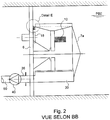
- An installation comprising the channel and the filtration device is represented on the Figures 1 to 3 .
- Such guides 5 are for example made of metal and each form a groove as shown in FIG. Figure 3 .
- the sluice 2 is equipped with a carrier plate or frame wall 6 extending from one wall 3 to the other 4 and which is slid vertically in the guides 5.
- the plate 6 has a circular opening centered substantially on the axis 13 of the plate 6. The lower part of the circular opening is located most generally very close to the bottom 14 of the opening 2.
- the circular opening is obstructed by a cylinder 7 concentric with the opening and which projects relative to to the carrier plate or chassis 6 upstream ( Figure 3 ) .
- the cylinder 7 consists of several spokes 8, a hub 9, a filter element 10 attached to the periphery of the cylinder 7.
- the spokes 8 extend from the hub 9 to the crosspieces 11 and are generally distributed in a regular manner around hub. These spokes 8 are integral with the filter element 10.
- the width of the partitions 12 is several centimeters from upstream to downstream.
- the partitions 12 are disposed at the periphery of the cylinder 7 and extend radially outwardly of the filter element 10, away from it.
- the partitions 12 are arranged longitudinally along generatrices of the cylinder 7, over the entire height thereof.
- the diameter of the cylinder 7 is preferably the largest possible, that is to say slightly less than the width of the sluice 2, in order to increase the filtration area as much as possible.
- the height of the cylinder can also be adjusted and increased if necessary. However, to avoid a bending of a cylinder too high under the action of its weight which normally would require to support the free end of the cylinder, it may be preferred to increase the diameter of the cylinder.
- the water flows from the inside of the filter cylinder outwards and the retaining elements are disposed inside the filter cylinder.
- the lowest water level rated PBE is usually located at least at the top level of the cylinder ( Figure 1 ). Alternatively, the PBE level may be higher or lower depending on additional constraints.
- the hub 9 of the cylinder is provided with bearings and mechanical stops known per se.
- the hub 9 is carried by a shaft 15 fixed to the support plate or wall 6 by radial arms 16.
- the plate 6 extends at least to a level generally equal to or greater than the level of the filter elements. higher water PHE not shown in the figures.
- the cylinder 7 is closed at its upstream end 7a which is opposite to the downstream end 7b situated opposite the central opening of the plate 6.
- the closure wall 7a has for example a conical shape in this example for hydraulic reasons.
- the cylinder 7, centered by the hub 9, is rotated by drive means having a peripheral gear teeth 17, a pinion 18 and a drive motor 19 (FIG. Figures 1 , 3 and 4 , detail E).
- a lip seal 20 is for example provided between the end 7b of the filter cylinder and the wall or plate 6.
- the filter element 10 protruding from the plate or wall 6 is conical with the base of the cone facing the opening of the plate or wall 6 and the tip of the cone directed upstream.
- a suction device comprising a longitudinal tangential trunk 30 ( Figures 1 , 2 and 4 ) extending along a generatrix of the cylinder 7.
- the horn 30 is fixed to the carrier plate 6 at one end ( Figure 2 ).
- the horn 30 has a cylindrical surface open over its entire height by a slot or opening 31 which is arranged axially, that is to say along the generatrices of said cylindrical surface and which faces the cylinder 7. The edges of the slot are then separated from each other to enlarge the latter.
- the cross section of the horn thus shaped has a U-shaped open profile whose opening is oriented towards the retaining elements of the filter element 10.
- the external volume of the cylinder 7 equipped with the filtering element 10 is circularly divided into compartments 32 by the parallel longitudinal partitions 12 forming the retaining elements.
- the horn 30 has, in plan, in a view taken from the cylinder 7, a rectangular contour equivalent or substantially greater than once that of such a compartment.
- the trunk 30 has an opening 31 facing the compartments 32 of the cylinder, which may be equipped with flexible lips 33, 34 to reduce the section, while allowing the occasional passage of larger bodies .
- the horn 30 is connected by a pipe 35 to a suction member such as a pump 40 attached to the wall 6, for example the downstream side thereof.
- the pipe 35 thus passes for example through the wall 6 and ensures the attachment of the horn 30 to the latter.
- the pump 40 fed for example by a cable (not shown), is chosen so as to pump large debris and, when necessary, a type also able to ensure a very high survival rate of fish. Water carrying debris, fish and other forms of aquatic life is discharged to its collection point by a pipe 50.
- the suction device comprises two horns respectively disposed on either side of the panel or cylindrical filter element, one downstream in the direction of the outflow, the other upstream. These two horns are arranged in correspondence with each other and both turned towards the cylindrical filter panel in cooperation with the relative rotational movement and a pump whose discharge is connected to the horn is arranged downstream.
- cylindrical filter panel a pump whose discharge is connected to the horn is arranged downstream.
- the exhaust pipe 50 comprises two debris concentrators (not shown) and a set of valves allowing an alternative service on one or the other of the concentrators.
- the evacuation pipe is devoid of concentrator and the water laden with debris and fish is discharged directly into a pipe or canal for a return to the natural environment.
- FIG. 1 to 3 there is shown an embodiment in which the suction device 30, 40 is fixed, while the drive means 17, 18, 19 are adapted to drive the cylindrical panel or filter element in rotation.
- the panel or filter element is fixed while the drive means are adapted to drive the suction device in rotation.
- the drive means are adapted / configured to drive in rotation both the suction device (s) (if there are several) and the cylindrical filter panel.
- the compartments or retaining elements have different adapted shapes (for example, a generally triangular shape for a cone), as well as the suction device.
- the operation of the sieve is as follows: when stopped, the filter cylinder 7 is stopped, the pump 40 does not work and the water flows through the filter element. The debris is stopped by the filter element 10 and retained in the longitudinal compartments 32 at the periphery of the cylinder.
- the pump 40 is started and the cylinder is rotated by the drive means 17, 18, 19.
- the cylinder rotates and the peripheral compartments 32 pass alternately in front of the opening 31 of the trunk 30.
- Each compartment is isolated from the general stream by the front of the trunk.
- the suction of the pump creates in the compartment a circulation in the opposite direction to that of normal sieving and with a speed of the same order.
- the debris is sucked into the horn 30, through the pump 40, and is evacuated via the pipe 50.
- the drive system 17, 18, 19 stops by the effect of a force limiter known per se and a rotation in the opposite direction is engaged, generally allowing to get rid of blocking debris.
- the washing pump 40 and the rotational movement are stopped at the end of the washing cycle.
- the pump used is of a suitable type and known per se.
- the operation is normally automatic and slaved to the pressure drop generated by the filter cylinder, that is to say, its fouling.
- Devices already known by themselves ensure the safety of the installation.
- the size of the debris to be sucked is limited by the inlet gate grille present in such intake structures. This debris can then be stored waiting for washing thanks to the dimension of compartments, especially at the distance between the surface of the filter element and the free end of the longitudinal partitions of said compartments.
- the filtration device or sieve according to the invention prevents any possibility of bypassing the system.
- Such a device / sieve according to the invention has the advantage of being introduced by sliding in vertical guides cooperating with structures carrying filters pass through chain.
- the filter element 10 may have openings of meshes of cylindrical, rectangular, square or slots with respective dimensions of the order of 10 x 10 to 0.5 x 0.5 mm.
- the device / sieve according to the invention also finds an application to the sluices having an inclination relative to the vertical plane.
Landscapes
- Chemical & Material Sciences (AREA)
- Chemical Kinetics & Catalysis (AREA)
- Health & Medical Sciences (AREA)
- Life Sciences & Earth Sciences (AREA)
- Engineering & Computer Science (AREA)
- Hydrology & Water Resources (AREA)
- Public Health (AREA)
- Water Supply & Treatment (AREA)
- Filtration Of Liquid (AREA)
- Farming Of Fish And Shellfish (AREA)
- Domestic Plumbing Installations (AREA)
Claims (13)
- Anlage, umfassend eine Leitung, in der Wasser fließt, und eine Filtervorrichtung zum Filtern des Wasserflusses in der Leitung (2), wobei der Wasserpegel in der Leitung zwischen einem niedrigsten Wasserpegel (PBE) und einem höchsten Wasserpegel (PHE) liegt, wobei die Vorrichtung umfasst:- eine Rahmenwand (6), die in der Leitung angebracht ist und eine Durchgangsöffnung aufweist,- eine Trommel mit einem Filterelement (10), die an der Rahmenwand im Bereich der Durchgangsöffnung angebracht ist und eine Filterfläche aufweist, die bezüglich der Wand stromaufwärts vorspringt, wobei die Filterfläche eine Umlauffläche ist, deren Drehachse senkrecht zur Durchgangsöffnung angeordnet ist und die größere Abmessungen als eine flache Filterfläche hat, die in der Durchgangsöffnung ausgebildet sein soll, wobei das Filterelement Rückhalteelemente (32) umfasst, die der Filterfläche gegenüberliegend stromaufwärts derselben ausgebildet sind, um Festkörper zurückzuhalten, die nicht durch die Filterfläche treten,- zumindest eine Saugvorrichtung (30, 40), die den Rückhalteelementen gegenüberliegend und stromaufwärts derselben angeordnet ist,- Antriebseinrichtungen (17, 18, 19) zum Antreiben des Filterelements und/oder der zumindest einen Saugvorrichtung zu einer relativen Bewegung zueinander, derart, dass die zumindest eine Saugvorrichtung nacheinander jedem Rückhalteelement gegenüberzuliegen kommt, um durch das Filterelement hindurch bereichsweise eine gegenläufige Wasserströmung im Bereich eines jeden Rückhalteelements zu bewirken,wobei die Anlage so ausgelegt ist, dass das obere Niveau der Trommel höchstens auf dem niedrigsten Wasserpegel (PBE) liegt.
- Anlage nach Anspruch 1, dadurch gekennzeichnet, dass die Filterfläche zylindrisch ist.
- Anlage nach Anspruch 2, dadurch gekennzeichnet, dass die Rückhalteelemente entlang von Mantellinien der zylindrischen Filterfläche parallel zueinander angeordnet sind.
- Anlage nach Anspruch 3, dadurch gekennzeichnet, dass die Rückhalteelemente aus zwei parallel zueinander verlaufenden, beabstandeten Trennwänden (12) gebildet sind, die entlang von Mantellinien der zylindrischen Filterfläche angeordnet sind.
- Anlage nach Anspruch 1, dadurch gekennzeichnet, dass die Filterfläche konisch verläuft.
- Anlage nach einem der Ansprüche 1 bis 5, dadurch gekennzeichnet, dass das Filterelement beweglich ist, während die zumindest eine Saugvorrichtung feststehend ist.
- Anlage nach einem der Ansprüche 1 bis 5, dadurch gekennzeichnet, dass das Filterelement feststehend ist, während die zumindest eine Saugvorrichtung beweglich ist.
- Anlage nach einem der Ansprüche 1 bis 5, dadurch gekennzeichnet, dass das Filterelement und die zumindest eine Saugvorrichtung beweglich sind.
- Anlage nach einem der Ansprüche 6 bis 8, dadurch gekennzeichnet, dass die Antriebseinrichtungen (17, 18, 19) dazu ausgelegt sind, das Filterelement, die zumindest eine Saugvorrichtung oder beide drehend anzutreiben.
- Anlage nach einem der Ansprüche 1 bis 9, dadurch gekennzeichnet, dass die Saugvorrichtung bzw. jede Saugvorrichtung - falls mehrere vorhanden sind - ein Saugorgan (40) und einen Saugrüssel (30) enthält, wobei ein Saugorgan mehreren Saugrüsseln gemein sein kann.
- Anlage nach den Ansprüchen 2 und 10, dadurch gekennzeichnet, dass der Saugrüssel (30) eine längliche Form hat und eine Mantelwand enthält, die im Querschnitt ein offenes Profil mit einer den Rückhalteelementen gegenüberliegenden Öffnung (31) aufweist.
- Anlage nach Anspruch 11, dadurch gekennzeichnet, dass das offene Profil eine U- oder C-Form hat.
- Anlage nach Anspruch 11 oder 12, dadurch gekennzeichnet, dass die Öffnung (31) im Grundriss eine im Wesentlichen rechteckförmige Kontur hat, deren Abmessungen gleich oder größer als die der gegenüberliegenden Rückhalteelemente sind.
Applications Claiming Priority (2)
| Application Number | Priority Date | Filing Date | Title |
|---|---|---|---|
| FR1157082A FR2978677B1 (fr) | 2011-08-02 | 2011-08-02 | Tamis a panneau filtrant cylindrique pour prise d'eau |
| US201161529408P | 2011-08-31 | 2011-08-31 |
Publications (2)
| Publication Number | Publication Date |
|---|---|
| EP2554231A1 EP2554231A1 (de) | 2013-02-06 |
| EP2554231B1 true EP2554231B1 (de) | 2018-12-05 |
Family
ID=46581852
Family Applications (1)
| Application Number | Title | Priority Date | Filing Date |
|---|---|---|---|
| EP12178819.4A Not-in-force EP2554231B1 (de) | 2011-08-02 | 2012-08-01 | Sieb mit zylindrischem Filterpaneel für Wasserentnahmestelle |
Country Status (6)
| Country | Link |
|---|---|
| US (3) | US9968872B2 (de) |
| EP (1) | EP2554231B1 (de) |
| CA (1) | CA2784621A1 (de) |
| CL (1) | CL2012002122A1 (de) |
| ES (1) | ES2713492T3 (de) |
| FR (1) | FR2978677B1 (de) |
Families Citing this family (21)
| Publication number | Priority date | Publication date | Assignee | Title |
|---|---|---|---|---|
| CN102712018B (zh) * | 2009-11-12 | 2015-10-07 | 过滤器安全有限公司 | 过滤器近端喷嘴 |
| US8647516B2 (en) * | 2010-09-03 | 2014-02-11 | Johnny Leon LOVE | Filtration method with self-cleaning filter assembly |
| US8297448B2 (en) * | 2010-11-22 | 2012-10-30 | Johnson Screens, Inc. | Screen intake device for shallow water |
| FR2978677B1 (fr) * | 2011-08-02 | 2014-10-17 | Beaudrey & Cie | Tamis a panneau filtrant cylindrique pour prise d'eau |
| US20140116965A1 (en) * | 2012-11-01 | 2014-05-01 | Machinerie Agricole Bois-Francs Inc. | Separator and method for separating a heterogeneous supply |
| US9567719B2 (en) * | 2013-04-03 | 2017-02-14 | Laitram, L.L.C. | Aquatic life and debris collection device for a water screen |
| NL2012621B1 (nl) * | 2014-04-15 | 2016-05-09 | Van Den Berg Bart | Trommelfilter voor waterfiltratie en werkwijze daarvoor. |
| SE539965C2 (en) * | 2015-06-23 | 2018-02-13 | Veolia Water Solutions & Tech | Filter panel with a controlled liquid lift, and a drum filter for filtering liquid |
| GB2551317A (en) * | 2016-06-07 | 2017-12-20 | Ide Technologies Ltd | Environmentally friendly water intake and pretreatment system |
| DE102017100952A1 (de) * | 2017-01-18 | 2018-07-19 | Aqseptence Group Gmbh | Siebvorrichtung mit verschwenkbaren Siebfeldern |
| US10195549B1 (en) * | 2017-11-21 | 2019-02-05 | Aqua-Aerobic Systems, Inc. | Backwash shoe method and apparatus that increases effective surface area of cloth filter media |
| CN108360657A (zh) * | 2018-02-10 | 2018-08-03 | 浙江泉峰建筑园林有限公司 | 一种市政建筑排水结构 |
| WO2020206556A1 (en) * | 2019-04-12 | 2020-10-15 | Cameron Farms Hutterite Colony | Fluid pumping apparatus and methods of use |
| SE543689C2 (en) * | 2019-10-04 | 2021-06-08 | Mimbly Ab | Improved filter assembly with self-cleaning |
| KR102183820B1 (ko) * | 2020-03-10 | 2020-11-30 | 주식회사 그레넥스 | 섬유상 여과기의 역세정 흡입장치 |
| FR3113071A1 (fr) | 2020-07-30 | 2022-02-04 | Eugene B | Ouvrage de genie civil et systeme de filtration de prise d’eau |
| CN112127460B (zh) * | 2020-09-27 | 2021-12-10 | 凤阳县和裕市政园林工程有限公司 | 一种适应不同水位的下水道防堵塞装置 |
| US12320087B2 (en) * | 2021-07-14 | 2025-06-03 | The United States Of America As Represented By The Secretary Of Agriculture | Submerged liquid intake strainers |
| CN113332789A (zh) * | 2021-08-05 | 2021-09-03 | 临沂盛荣环保科技有限公司 | 一种废水环保处理装置 |
| WO2023037364A1 (en) * | 2021-09-10 | 2023-03-16 | Algaecore Technologies Ltd | Rotary drum filtering machine for algae filtration |
| CN119951204A (zh) * | 2025-01-03 | 2025-05-09 | 南京红远环保科技有限公司 | 一种石墨烯mbr膜丝生产设备 |
Family Cites Families (51)
| Publication number | Priority date | Publication date | Assignee | Title |
|---|---|---|---|---|
| US1516693A (en) * | 1924-11-25 | Newcastle-upon-tyne | ||
| US2142737A (en) * | 1939-01-03 | Sewage screening apparatus | ||
| DE637108C (de) * | 1936-10-21 | Josef Moehring | Reinigungseinrichtung der Wandung einer dem Entschlammen von Abwaessern dienenden Siebtrommel | |
| FR406776A (fr) | 1909-09-04 | 1910-02-10 | Europ Brake Shoe C | Procédé perfectionné pour la fonte des métaux |
| US1210759A (en) * | 1914-02-07 | 1917-01-02 | Johannes Paul Breddin | Apparatus for purifying sewage-water. |
| US1188340A (en) * | 1916-02-12 | 1916-06-20 | Sewage Clarification Company | Filtration apparatus and system. |
| US2013971A (en) * | 1928-05-04 | 1935-09-10 | Municipal Sanitary Service Cor | Automatic screening and filtering apparatus |
| US2022336A (en) * | 1935-01-30 | 1935-11-26 | Joseph E Bower | Self cleaning screen |
| US2295937A (en) * | 1939-12-05 | 1942-09-15 | Louis E Crane | Screen separator |
| DE734268C (de) * | 1940-08-04 | 1943-04-12 | Josef Moehring | Reinigungseinrichtung der Wandung einer Siebtrommel |
| US2624461A (en) * | 1949-08-13 | 1953-01-06 | American Cyanamid Co | Float removal device for rotatable type heavy-media separators |
| NL254526A (de) * | 1959-10-30 | |||
| US3606735A (en) * | 1969-07-01 | 1971-09-21 | Aeronca Inc | Air filter assembly providing increased filtering surface area for a given volumetric size |
| US3622006A (en) * | 1969-10-20 | 1971-11-23 | Marc M Brunner | Self-cleaning strainer for pipeline |
| US3825124A (en) * | 1970-07-27 | 1974-07-23 | Envirotech Corp | Filter elements for continuous filters |
| US3812967A (en) * | 1973-02-05 | 1974-05-28 | S Rudzinski | Screening and comminuting device |
| US4038187A (en) * | 1976-02-03 | 1977-07-26 | Envirex Inc. | Microscreen drum |
| US4062776A (en) * | 1976-07-07 | 1977-12-13 | Arie Blok | Sludge concentrator and conditioner |
| FR2396123A1 (fr) * | 1977-07-01 | 1979-01-26 | Beaudrey & Cie | Tamis de prise d'eau a dispositif de sauvegarde pour la protection des elements vivants, en particulier poissons, et dispositif de sauvegarde correspondant |
| US4140629A (en) * | 1977-09-15 | 1979-02-20 | Martco, Inc. | Conical screen separator |
| DE2827996A1 (de) * | 1978-06-26 | 1980-01-17 | Stengelin Volker | Vorrichtung zur biologischen reinigung von abwasser |
| US4210539A (en) * | 1978-10-10 | 1980-07-01 | Shiban Samir S | Water screen |
| FR2475091A1 (fr) * | 1980-02-05 | 1981-08-07 | Beaudrey Et Cie Sa E | Prise d'eau a dispositif de sauvegarde pour elements vivants |
| FR2477195A1 (fr) * | 1980-03-03 | 1981-09-04 | Beaudrey & Cie | Filtre a chaine a double flux, et procede pour sa substitution a un filtre a chaine a passage direct |
| US4551248A (en) * | 1983-06-03 | 1985-11-05 | Dorr-Oliver Incorporated | Filter drum for rotary drum vacuum filter |
| US4487695A (en) * | 1983-12-27 | 1984-12-11 | Connolly James D | Centrifuge screen basket |
| FR2561940B1 (fr) * | 1984-03-27 | 1986-07-04 | Electricite De France | Dispositif de recuperation des organismes vivants sur les filtres rotatifs de stations de pompage d'eau |
| US4521305A (en) * | 1984-03-28 | 1985-06-04 | Deal Troy M | Rotating self-cleaning screen |
| US5094751A (en) * | 1989-08-21 | 1992-03-10 | Champion International Corporation | Self-cleaning filter assembly |
| USD327693S (en) * | 1989-11-07 | 1992-07-07 | Berry Russell M | Pump intake screen support frame |
| US5116490A (en) * | 1990-03-21 | 1992-05-26 | Herman Fontenot | Rotary screen apparatus for use with cooling towers |
| ES2077309T3 (es) * | 1991-07-31 | 1995-11-16 | Tonne Hansjochen E Dipl Ing | Dispositivo y procedimiento para el filtrado de particulas solidas a partir de liquidos. |
| US5378364A (en) * | 1992-09-14 | 1995-01-03 | Baker Hughes Incorporated | Conical screen basket centrifuge |
| US5300225A (en) * | 1992-10-15 | 1994-04-05 | Fischer Harry C | Vacuum cleaned micro-strainer system |
| DE4339268C2 (de) * | 1993-11-18 | 1996-01-25 | Huber Hans Gmbh Maschinen Und | Verfahren und Vorrichtung zum Ausfiltern und Rückspülen von Feststoff-Partikeln aus Flüssigkeiten |
| US5851087A (en) * | 1996-11-07 | 1998-12-22 | Berry, Iii; Russell M. | Self-cleaning intake screen |
| US6089790A (en) * | 1996-11-07 | 2000-07-18 | Berry, Iii; Russell M. | Self-cleaning intake screen |
| US6572763B2 (en) * | 1998-08-21 | 2003-06-03 | Donald B. Gorshing | Wastewater screening, washing and dewatering system |
| BR0100425C2 (pt) * | 2001-01-12 | 2003-12-02 | Daniel Villares Lenz Cesar | Filtro autolimpante |
| US8083939B2 (en) * | 2003-10-03 | 2011-12-27 | Weatherford Australia Pty Limited | Screen nozzle |
| US7347933B2 (en) * | 2003-11-17 | 2008-03-25 | Intake Screens, Inc. | Self-cleaning intake screen |
| FR2871820B1 (fr) * | 2004-06-22 | 2006-09-22 | Beaudrey Et Cie Sa E | Tamis a panneau filtrant circulaire pour prise d'eau |
| FR2874334B1 (fr) | 2004-08-20 | 2006-11-24 | Beaudrey Et Cie Sa E | Tamis rotatif pour prise d'eau |
| US20070090041A1 (en) * | 2005-10-25 | 2007-04-26 | Berry Russell M Iii | Self-cleaning intake screen |
| US7615148B1 (en) * | 2007-04-18 | 2009-11-10 | Gentry David W | Seawall filter |
| US7833303B1 (en) * | 2007-08-08 | 2010-11-16 | Charles George Higgins | Sifting apparatus with filter rotation and particle collection |
| CA2735756A1 (en) * | 2011-03-31 | 2012-09-30 | Craig Hopf | Weed and trash screening apparatus for irrigation systems |
| FR2978677B1 (fr) * | 2011-08-02 | 2014-10-17 | Beaudrey & Cie | Tamis a panneau filtrant cylindrique pour prise d'eau |
| US20150265952A1 (en) * | 2014-03-18 | 2015-09-24 | Intake Screens, Inc. | Self-Cleaning Intake Screen |
| NL2012621B1 (nl) * | 2014-04-15 | 2016-05-09 | Van Den Berg Bart | Trommelfilter voor waterfiltratie en werkwijze daarvoor. |
| US10124281B2 (en) * | 2016-07-28 | 2018-11-13 | Jet Filter System Llc | Filter assembly for retaining wall drain holes |
-
2011
- 2011-08-02 FR FR1157082A patent/FR2978677B1/fr not_active Expired - Fee Related
-
2012
- 2012-07-25 CA CA2784621A patent/CA2784621A1/fr not_active Abandoned
- 2012-07-31 US US13/562,669 patent/US9968872B2/en not_active Expired - Fee Related
- 2012-07-31 CL CL2012002122A patent/CL2012002122A1/es unknown
- 2012-08-01 EP EP12178819.4A patent/EP2554231B1/de not_active Not-in-force
- 2012-08-01 ES ES12178819T patent/ES2713492T3/es active Active
-
2017
- 2017-11-17 US US15/816,225 patent/US10391429B2/en not_active Expired - Fee Related
-
2019
- 2019-02-27 US US16/287,729 patent/US10549224B2/en not_active Expired - Fee Related
Non-Patent Citations (1)
| Title |
|---|
| None * |
Also Published As
| Publication number | Publication date |
|---|---|
| FR2978677A1 (fr) | 2013-02-08 |
| ES2713492T3 (es) | 2019-05-22 |
| US20190193004A1 (en) | 2019-06-27 |
| CA2784621A1 (fr) | 2013-02-02 |
| US9968872B2 (en) | 2018-05-15 |
| US10549224B2 (en) | 2020-02-04 |
| FR2978677B1 (fr) | 2014-10-17 |
| US10391429B2 (en) | 2019-08-27 |
| CL2012002122A1 (es) | 2013-05-17 |
| US20130032515A1 (en) | 2013-02-07 |
| US20180071663A1 (en) | 2018-03-15 |
| EP2554231A1 (de) | 2013-02-06 |
Similar Documents
| Publication | Publication Date | Title |
|---|---|---|
| EP2554231A1 (de) | Sieb mit zylindrischem Filterpaneel für Wasserentnahmestelle | |
| EP0160590B1 (de) | Vorrichtung zur Rückgewinnung lebender Organismen auf Drehfiltern von Wasserpumpanlagen | |
| EP3109583B1 (de) | System zum abfangen und sammeln von reinigungskörpern durch alternatives kehren | |
| FR2524826A1 (fr) | Dispositif de lavage de tamis rotatifs pour prises d'eau d'installations industrielles | |
| FR2871820A1 (fr) | Tamis a panneau filtrant circulaire pour prise d'eau | |
| EP1735510A1 (de) | Mit einer rückflusssperreinlassleitung versehene reinigungsvorrichtung mit eingetauchter fläche | |
| FR2874334A1 (fr) | Tamis rotatif pour prise d'eau | |
| FR2503577A1 (fr) | Filtre a tablier filtrant mobile | |
| FR2609643A1 (fr) | Panneau filtrant a canaux paralleles et tamis mecanique comportant de tels panneaux filtrants | |
| EP0353154A1 (de) | Vorrichtung zum Abscheiden von abgeriebenen Reinigungskugeln aus Rohrbündeln | |
| WO1990010488A1 (fr) | Dispositif de filtration et d'evacuation de petites particules, dechets et detritus, de natures diverses | |
| FR2960161A1 (fr) | Dispositif de tamisage pour alimentation en eau d'une installation industrielle | |
| FR3013230A1 (fr) | Tambour filtrant et panneau filtrant pouvant equiper un tel tambour | |
| EP2730725B1 (de) | Reguliervorrichtung des Durchsatzes eines Skimmers in einem Becken mit Wasserfalleffekt | |
| FR2972116A1 (fr) | Appareil de filtration et installation de filtration comprenant un tel appareil | |
| EP2181748B1 (de) | Hdrodynamischer separator zur Reinigung eines Fluidstromes | |
| WO2023118428A1 (fr) | Dispositif de filtrage autonettoyant | |
| EP3717094B1 (de) | Tauchfilter für ein schwimmbad | |
| FR2877856A1 (fr) | Ensemble de filtration d'eau pour piscine, et ensemble a cartouche et panier | |
| FR2990877A1 (fr) | Systeme et procede de filtration d'un ecoulement d'eau | |
| FR2975305A1 (fr) | Dispositif de retenue de dechets dans un cours d'eau, dispositif de nettoyage et systeme de filtrage associes | |
| FR2746031A1 (fr) | Procede et installation de filtration d'un liquide | |
| FR3092259A1 (fr) | Systeme d’interception et de collecte de corps nettoyants par balayage alternatif | |
| FR2945959A1 (fr) | Tambour filtrant rotatif et installation de filtration comportant un tel tambour | |
| EP0223893B1 (de) | Selbstreinigender Filter und Rechen für Kanäle und industrielle Anwendung |
Legal Events
| Date | Code | Title | Description |
|---|---|---|---|
| PUAI | Public reference made under article 153(3) epc to a published international application that has entered the european phase |
Free format text: ORIGINAL CODE: 0009012 |
|
| AK | Designated contracting states |
Kind code of ref document: A1 Designated state(s): AL AT BE BG CH CY CZ DE DK EE ES FI FR GB GR HR HU IE IS IT LI LT LU LV MC MK MT NL NO PL PT RO RS SE SI SK SM TR |
|
| AX | Request for extension of the european patent |
Extension state: BA ME |
|
| 17P | Request for examination filed |
Effective date: 20130702 |
|
| RBV | Designated contracting states (corrected) |
Designated state(s): AL AT BE BG CH CY CZ DE DK EE ES FI FR GB GR HR HU IE IS IT LI LT LU LV MC MK MT NL NO PL PT RO RS SE SI SK SM TR |
|
| 17Q | First examination report despatched |
Effective date: 20150729 |
|
| STAA | Information on the status of an ep patent application or granted ep patent |
Free format text: STATUS: EXAMINATION IS IN PROGRESS |
|
| GRAP | Despatch of communication of intention to grant a patent |
Free format text: ORIGINAL CODE: EPIDOSNIGR1 |
|
| STAA | Information on the status of an ep patent application or granted ep patent |
Free format text: STATUS: GRANT OF PATENT IS INTENDED |
|
| INTG | Intention to grant announced |
Effective date: 20180705 |
|
| GRAS | Grant fee paid |
Free format text: ORIGINAL CODE: EPIDOSNIGR3 |
|
| GRAA | (expected) grant |
Free format text: ORIGINAL CODE: 0009210 |
|
| GRAA | (expected) grant |
Free format text: ORIGINAL CODE: 0009210 |
|
| STAA | Information on the status of an ep patent application or granted ep patent |
Free format text: STATUS: THE PATENT HAS BEEN GRANTED |
|
| AK | Designated contracting states |
Kind code of ref document: B1 Designated state(s): AL AT BE BG CH CY CZ DE DK EE ES FI FR GB GR HR HU IE IS IT LI LT LU LV MC MK MT NL NO PL PT RO RS SE SI SK SM TR |
|
| REG | Reference to a national code |
Ref country code: GB Ref legal event code: FG4D Free format text: NOT ENGLISH |
|
| REG | Reference to a national code |
Ref country code: CH Ref legal event code: EP |
|
| REG | Reference to a national code |
Ref country code: AT Ref legal event code: REF Ref document number: 1072355 Country of ref document: AT Kind code of ref document: T Effective date: 20181215 |
|
| REG | Reference to a national code |
Ref country code: DE Ref legal event code: R096 Ref document number: 602012054260 Country of ref document: DE |
|
| REG | Reference to a national code |
Ref country code: IE Ref legal event code: FG4D Free format text: LANGUAGE OF EP DOCUMENT: FRENCH |
|
| REG | Reference to a national code |
Ref country code: NL Ref legal event code: FP |
|
| REG | Reference to a national code |
Ref country code: AT Ref legal event code: MK05 Ref document number: 1072355 Country of ref document: AT Kind code of ref document: T Effective date: 20181205 |
|
| REG | Reference to a national code |
Ref country code: LT Ref legal event code: MG4D |
|
| PG25 | Lapsed in a contracting state [announced via postgrant information from national office to epo] |
Ref country code: NO Free format text: LAPSE BECAUSE OF FAILURE TO SUBMIT A TRANSLATION OF THE DESCRIPTION OR TO PAY THE FEE WITHIN THE PRESCRIBED TIME-LIMIT Effective date: 20190305 Ref country code: LT Free format text: LAPSE BECAUSE OF FAILURE TO SUBMIT A TRANSLATION OF THE DESCRIPTION OR TO PAY THE FEE WITHIN THE PRESCRIBED TIME-LIMIT Effective date: 20181205 Ref country code: BG Free format text: LAPSE BECAUSE OF FAILURE TO SUBMIT A TRANSLATION OF THE DESCRIPTION OR TO PAY THE FEE WITHIN THE PRESCRIBED TIME-LIMIT Effective date: 20190305 Ref country code: FI Free format text: LAPSE BECAUSE OF FAILURE TO SUBMIT A TRANSLATION OF THE DESCRIPTION OR TO PAY THE FEE WITHIN THE PRESCRIBED TIME-LIMIT Effective date: 20181205 Ref country code: LV Free format text: LAPSE BECAUSE OF FAILURE TO SUBMIT A TRANSLATION OF THE DESCRIPTION OR TO PAY THE FEE WITHIN THE PRESCRIBED TIME-LIMIT Effective date: 20181205 Ref country code: HR Free format text: LAPSE BECAUSE OF FAILURE TO SUBMIT A TRANSLATION OF THE DESCRIPTION OR TO PAY THE FEE WITHIN THE PRESCRIBED TIME-LIMIT Effective date: 20181205 Ref country code: AT Free format text: LAPSE BECAUSE OF FAILURE TO SUBMIT A TRANSLATION OF THE DESCRIPTION OR TO PAY THE FEE WITHIN THE PRESCRIBED TIME-LIMIT Effective date: 20181205 |
|
| REG | Reference to a national code |
Ref country code: ES Ref legal event code: FG2A Ref document number: 2713492 Country of ref document: ES Kind code of ref document: T3 Effective date: 20190522 |
|
| PG25 | Lapsed in a contracting state [announced via postgrant information from national office to epo] |
Ref country code: AL Free format text: LAPSE BECAUSE OF FAILURE TO SUBMIT A TRANSLATION OF THE DESCRIPTION OR TO PAY THE FEE WITHIN THE PRESCRIBED TIME-LIMIT Effective date: 20181205 Ref country code: SE Free format text: LAPSE BECAUSE OF FAILURE TO SUBMIT A TRANSLATION OF THE DESCRIPTION OR TO PAY THE FEE WITHIN THE PRESCRIBED TIME-LIMIT Effective date: 20181205 Ref country code: GR Free format text: LAPSE BECAUSE OF FAILURE TO SUBMIT A TRANSLATION OF THE DESCRIPTION OR TO PAY THE FEE WITHIN THE PRESCRIBED TIME-LIMIT Effective date: 20190306 Ref country code: RS Free format text: LAPSE BECAUSE OF FAILURE TO SUBMIT A TRANSLATION OF THE DESCRIPTION OR TO PAY THE FEE WITHIN THE PRESCRIBED TIME-LIMIT Effective date: 20181205 |
|
| PG25 | Lapsed in a contracting state [announced via postgrant information from national office to epo] |
Ref country code: PL Free format text: LAPSE BECAUSE OF FAILURE TO SUBMIT A TRANSLATION OF THE DESCRIPTION OR TO PAY THE FEE WITHIN THE PRESCRIBED TIME-LIMIT Effective date: 20181205 Ref country code: PT Free format text: LAPSE BECAUSE OF FAILURE TO SUBMIT A TRANSLATION OF THE DESCRIPTION OR TO PAY THE FEE WITHIN THE PRESCRIBED TIME-LIMIT Effective date: 20190405 Ref country code: CZ Free format text: LAPSE BECAUSE OF FAILURE TO SUBMIT A TRANSLATION OF THE DESCRIPTION OR TO PAY THE FEE WITHIN THE PRESCRIBED TIME-LIMIT Effective date: 20181205 |
|
| PG25 | Lapsed in a contracting state [announced via postgrant information from national office to epo] |
Ref country code: IS Free format text: LAPSE BECAUSE OF FAILURE TO SUBMIT A TRANSLATION OF THE DESCRIPTION OR TO PAY THE FEE WITHIN THE PRESCRIBED TIME-LIMIT Effective date: 20190405 Ref country code: EE Free format text: LAPSE BECAUSE OF FAILURE TO SUBMIT A TRANSLATION OF THE DESCRIPTION OR TO PAY THE FEE WITHIN THE PRESCRIBED TIME-LIMIT Effective date: 20181205 Ref country code: SM Free format text: LAPSE BECAUSE OF FAILURE TO SUBMIT A TRANSLATION OF THE DESCRIPTION OR TO PAY THE FEE WITHIN THE PRESCRIBED TIME-LIMIT Effective date: 20181205 Ref country code: SK Free format text: LAPSE BECAUSE OF FAILURE TO SUBMIT A TRANSLATION OF THE DESCRIPTION OR TO PAY THE FEE WITHIN THE PRESCRIBED TIME-LIMIT Effective date: 20181205 Ref country code: RO Free format text: LAPSE BECAUSE OF FAILURE TO SUBMIT A TRANSLATION OF THE DESCRIPTION OR TO PAY THE FEE WITHIN THE PRESCRIBED TIME-LIMIT Effective date: 20181205 |
|
| REG | Reference to a national code |
Ref country code: DE Ref legal event code: R097 Ref document number: 602012054260 Country of ref document: DE |
|
| PLBE | No opposition filed within time limit |
Free format text: ORIGINAL CODE: 0009261 |
|
| STAA | Information on the status of an ep patent application or granted ep patent |
Free format text: STATUS: NO OPPOSITION FILED WITHIN TIME LIMIT |
|
| PG25 | Lapsed in a contracting state [announced via postgrant information from national office to epo] |
Ref country code: DK Free format text: LAPSE BECAUSE OF FAILURE TO SUBMIT A TRANSLATION OF THE DESCRIPTION OR TO PAY THE FEE WITHIN THE PRESCRIBED TIME-LIMIT Effective date: 20181205 Ref country code: SI Free format text: LAPSE BECAUSE OF FAILURE TO SUBMIT A TRANSLATION OF THE DESCRIPTION OR TO PAY THE FEE WITHIN THE PRESCRIBED TIME-LIMIT Effective date: 20181205 |
|
| 26N | No opposition filed |
Effective date: 20190906 |
|
| PG25 | Lapsed in a contracting state [announced via postgrant information from national office to epo] |
Ref country code: TR Free format text: LAPSE BECAUSE OF FAILURE TO SUBMIT A TRANSLATION OF THE DESCRIPTION OR TO PAY THE FEE WITHIN THE PRESCRIBED TIME-LIMIT Effective date: 20181205 |
|
| PG25 | Lapsed in a contracting state [announced via postgrant information from national office to epo] |
Ref country code: LU Free format text: LAPSE BECAUSE OF NON-PAYMENT OF DUE FEES Effective date: 20190801 Ref country code: LI Free format text: LAPSE BECAUSE OF NON-PAYMENT OF DUE FEES Effective date: 20190831 Ref country code: MC Free format text: LAPSE BECAUSE OF FAILURE TO SUBMIT A TRANSLATION OF THE DESCRIPTION OR TO PAY THE FEE WITHIN THE PRESCRIBED TIME-LIMIT Effective date: 20181205 Ref country code: CH Free format text: LAPSE BECAUSE OF NON-PAYMENT OF DUE FEES Effective date: 20190831 |
|
| REG | Reference to a national code |
Ref country code: BE Ref legal event code: MM Effective date: 20190831 |
|
| PG25 | Lapsed in a contracting state [announced via postgrant information from national office to epo] |
Ref country code: IE Free format text: LAPSE BECAUSE OF NON-PAYMENT OF DUE FEES Effective date: 20190801 |
|
| PG25 | Lapsed in a contracting state [announced via postgrant information from national office to epo] |
Ref country code: BE Free format text: LAPSE BECAUSE OF NON-PAYMENT OF DUE FEES Effective date: 20190831 |
|
| PG25 | Lapsed in a contracting state [announced via postgrant information from national office to epo] |
Ref country code: CY Free format text: LAPSE BECAUSE OF FAILURE TO SUBMIT A TRANSLATION OF THE DESCRIPTION OR TO PAY THE FEE WITHIN THE PRESCRIBED TIME-LIMIT Effective date: 20181205 |
|
| PG25 | Lapsed in a contracting state [announced via postgrant information from national office to epo] |
Ref country code: MT Free format text: LAPSE BECAUSE OF FAILURE TO SUBMIT A TRANSLATION OF THE DESCRIPTION OR TO PAY THE FEE WITHIN THE PRESCRIBED TIME-LIMIT Effective date: 20181205 Ref country code: HU Free format text: LAPSE BECAUSE OF FAILURE TO SUBMIT A TRANSLATION OF THE DESCRIPTION OR TO PAY THE FEE WITHIN THE PRESCRIBED TIME-LIMIT; INVALID AB INITIO Effective date: 20120801 |
|
| PGFP | Annual fee paid to national office [announced via postgrant information from national office to epo] |
Ref country code: NL Payment date: 20210816 Year of fee payment: 10 |
|
| PGFP | Annual fee paid to national office [announced via postgrant information from national office to epo] |
Ref country code: IT Payment date: 20210817 Year of fee payment: 10 Ref country code: FR Payment date: 20210730 Year of fee payment: 10 |
|
| PGFP | Annual fee paid to national office [announced via postgrant information from national office to epo] |
Ref country code: ES Payment date: 20210903 Year of fee payment: 10 Ref country code: GB Payment date: 20210719 Year of fee payment: 10 Ref country code: DE Payment date: 20210811 Year of fee payment: 10 |
|
| PG25 | Lapsed in a contracting state [announced via postgrant information from national office to epo] |
Ref country code: MK Free format text: LAPSE BECAUSE OF FAILURE TO SUBMIT A TRANSLATION OF THE DESCRIPTION OR TO PAY THE FEE WITHIN THE PRESCRIBED TIME-LIMIT Effective date: 20181205 |
|
| REG | Reference to a national code |
Ref country code: DE Ref legal event code: R119 Ref document number: 602012054260 Country of ref document: DE |
|
| REG | Reference to a national code |
Ref country code: NL Ref legal event code: MM Effective date: 20220901 |
|
| GBPC | Gb: european patent ceased through non-payment of renewal fee |
Effective date: 20220801 |
|
| PG25 | Lapsed in a contracting state [announced via postgrant information from national office to epo] |
Ref country code: NL Free format text: LAPSE BECAUSE OF NON-PAYMENT OF DUE FEES Effective date: 20220901 |
|
| PG25 | Lapsed in a contracting state [announced via postgrant information from national office to epo] |
Ref country code: IT Free format text: LAPSE BECAUSE OF NON-PAYMENT OF DUE FEES Effective date: 20220801 Ref country code: FR Free format text: LAPSE BECAUSE OF NON-PAYMENT OF DUE FEES Effective date: 20220831 Ref country code: DE Free format text: LAPSE BECAUSE OF NON-PAYMENT OF DUE FEES Effective date: 20230301 |
|
| REG | Reference to a national code |
Ref country code: ES Ref legal event code: FD2A Effective date: 20230928 |
|
| PG25 | Lapsed in a contracting state [announced via postgrant information from national office to epo] |
Ref country code: GB Free format text: LAPSE BECAUSE OF NON-PAYMENT OF DUE FEES Effective date: 20220801 Ref country code: ES Free format text: LAPSE BECAUSE OF NON-PAYMENT OF DUE FEES Effective date: 20220802 |