EP2181752B1 - Verfahren zur Behandlung von Fluiden mittels Druck-Wechsel-Adsorption - Google Patents
Verfahren zur Behandlung von Fluiden mittels Druck-Wechsel-Adsorption Download PDFInfo
- Publication number
- EP2181752B1 EP2181752B1 EP09173745.2A EP09173745A EP2181752B1 EP 2181752 B1 EP2181752 B1 EP 2181752B1 EP 09173745 A EP09173745 A EP 09173745A EP 2181752 B1 EP2181752 B1 EP 2181752B1
- Authority
- EP
- European Patent Office
- Prior art keywords
- adsorber
- oxygen
- fluid
- flow rate
- extraction
- Prior art date
- Legal status (The legal status is an assumption and is not a legal conclusion. Google has not performed a legal analysis and makes no representation as to the accuracy of the status listed.)
- Active
Links
Images


Classifications
-
- B—PERFORMING OPERATIONS; TRANSPORTING
- B01—PHYSICAL OR CHEMICAL PROCESSES OR APPARATUS IN GENERAL
- B01D—SEPARATION
- B01D53/00—Separation of gases or vapours; Recovering vapours of volatile solvents from gases; Chemical or biological purification of waste gases, e.g. engine exhaust gases, smoke, fumes, flue gases, aerosols
- B01D53/02—Separation of gases or vapours; Recovering vapours of volatile solvents from gases; Chemical or biological purification of waste gases, e.g. engine exhaust gases, smoke, fumes, flue gases, aerosols by adsorption, e.g. preparative gas chromatography
- B01D53/04—Separation of gases or vapours; Recovering vapours of volatile solvents from gases; Chemical or biological purification of waste gases, e.g. engine exhaust gases, smoke, fumes, flue gases, aerosols by adsorption, e.g. preparative gas chromatography with stationary adsorbents
- B01D53/047—Pressure swing adsorption
-
- B—PERFORMING OPERATIONS; TRANSPORTING
- B01—PHYSICAL OR CHEMICAL PROCESSES OR APPARATUS IN GENERAL
- B01D—SEPARATION
- B01D2256/00—Main component in the product gas stream after treatment
- B01D2256/12—Oxygen
-
- B—PERFORMING OPERATIONS; TRANSPORTING
- B01—PHYSICAL OR CHEMICAL PROCESSES OR APPARATUS IN GENERAL
- B01D—SEPARATION
- B01D2257/00—Components to be removed
- B01D2257/10—Single element gases other than halogens
- B01D2257/102—Nitrogen
-
- B—PERFORMING OPERATIONS; TRANSPORTING
- B01—PHYSICAL OR CHEMICAL PROCESSES OR APPARATUS IN GENERAL
- B01D—SEPARATION
- B01D2259/00—Type of treatment
- B01D2259/40—Further details for adsorption processes and devices
- B01D2259/40007—Controlling pressure or temperature swing adsorption
- B01D2259/40009—Controlling pressure or temperature swing adsorption using sensors or gas analysers
-
- B—PERFORMING OPERATIONS; TRANSPORTING
- B01—PHYSICAL OR CHEMICAL PROCESSES OR APPARATUS IN GENERAL
- B01D—SEPARATION
- B01D2259/00—Type of treatment
- B01D2259/40—Further details for adsorption processes and devices
- B01D2259/40011—Methods relating to the process cycle in pressure or temperature swing adsorption
- B01D2259/4002—Production
- B01D2259/40022—Production with two sub-steps
-
- B—PERFORMING OPERATIONS; TRANSPORTING
- B01—PHYSICAL OR CHEMICAL PROCESSES OR APPARATUS IN GENERAL
- B01D—SEPARATION
- B01D2259/00—Type of treatment
- B01D2259/40—Further details for adsorption processes and devices
- B01D2259/40011—Methods relating to the process cycle in pressure or temperature swing adsorption
- B01D2259/40043—Purging
- B01D2259/4005—Nature of purge gas
- B01D2259/40052—Recycled product or process gas
-
- B—PERFORMING OPERATIONS; TRANSPORTING
- B01—PHYSICAL OR CHEMICAL PROCESSES OR APPARATUS IN GENERAL
- B01D—SEPARATION
- B01D2259/00—Type of treatment
- B01D2259/40—Further details for adsorption processes and devices
- B01D2259/40011—Methods relating to the process cycle in pressure or temperature swing adsorption
- B01D2259/40058—Number of sequence steps, including sub-steps, per cycle
- B01D2259/40073—Ten
-
- B—PERFORMING OPERATIONS; TRANSPORTING
- B01—PHYSICAL OR CHEMICAL PROCESSES OR APPARATUS IN GENERAL
- B01D—SEPARATION
- B01D2259/00—Type of treatment
- B01D2259/40—Further details for adsorption processes and devices
- B01D2259/402—Further details for adsorption processes and devices using two beds
-
- B—PERFORMING OPERATIONS; TRANSPORTING
- B01—PHYSICAL OR CHEMICAL PROCESSES OR APPARATUS IN GENERAL
- B01D—SEPARATION
- B01D2259/00—Type of treatment
- B01D2259/45—Gas separation or purification devices adapted for specific applications
- B01D2259/4533—Gas separation or purification devices adapted for specific applications for medical purposes
-
- B—PERFORMING OPERATIONS; TRANSPORTING
- B01—PHYSICAL OR CHEMICAL PROCESSES OR APPARATUS IN GENERAL
- B01D—SEPARATION
- B01D53/00—Separation of gases or vapours; Recovering vapours of volatile solvents from gases; Chemical or biological purification of waste gases, e.g. engine exhaust gases, smoke, fumes, flue gases, aerosols
- B01D53/02—Separation of gases or vapours; Recovering vapours of volatile solvents from gases; Chemical or biological purification of waste gases, e.g. engine exhaust gases, smoke, fumes, flue gases, aerosols by adsorption, e.g. preparative gas chromatography
- B01D53/04—Separation of gases or vapours; Recovering vapours of volatile solvents from gases; Chemical or biological purification of waste gases, e.g. engine exhaust gases, smoke, fumes, flue gases, aerosols by adsorption, e.g. preparative gas chromatography with stationary adsorbents
- B01D53/0407—Constructional details of adsorbing systems
- B01D53/0446—Means for feeding or distributing gases
Definitions
- the invention relates to a pressure swing adsorption fluid treatment process.
- Oxygen is generally considered a drug, particularly in France, the purity of medical oxygen being of the order of 99.5%.
- Such an oxygen supply requires nearby oxygen plants, from which bottles or liquid oxygen are transported.
- FIG. 1 An installation of the prior art is shown schematically in figure 1 .
- This comprises a first and a second adsorber 1a, 1b, each having an adsorbent bed capable of separating oxygen from the air. Since the air consists essentially of oxygen and nitrogen, the adsorbent bed is used to trap nitrogen in order to increase the oxygen concentration. More particularly, the adsorbent bed is a molecular sieve consisting of zeolite beads.
- Each adsorber 1a, 1b has a feed inlet 2a, 2b connected to an air supply pipe 3 via a so-called supply solenoid valve 4a, 4b and an extraction outlet 5a, 5b of the oxygen produced, connected to a discharge pipe 6 via a non-return valve 7-a , 7-b.
- Each inlet 2a, 2b adsorbers 1a, 1b is further connected to a muffler purge or extraction 8 via a solenoid valve 9a, 9b called regeneration.
- outlets 5a, 5b of the adsorbers 1a, 1b are interconnected via a first connecting pipe 10 equipped with an adjustable flow restrictor 11, and a second connecting pipe 12 equipped with a balancing valve 13.
- valves 4a and 9b are open and the valves 4b, 9a and 13 are closed.
- the pressurized air is fed through the air supply pipe 3, passes through the supply valve 4a associated with the first adsorber 1a, and enters the latter so that the oxygen contained in the air is separated from the nitrogen and then rejected at the outlet 5a.
- the pressure P1 at the outlet 5a of the first adsorber 1a increases.
- the opening of the regeneration valve 9b allows the gas retained in the second adsorber 1b to escape suddenly through the purge silencer 8.
- the pressure in the second adsorber 1b typically ranges from about 2.5 bar to 0.degree. bar in a fraction of a second, which allows to desorb the nitrogen trapped in the adsorbent bed.
- the second adsorber 1b is flushed with a stream of oxygen from the bond 10 between the outlets 5a, 5b of the first and second adsorbers 1a, 1b to complete the desorption of nitrogen.
- this stream of oxygen remains minimal because of the presence of a flow restrictor 11.
- a time management system After a determined period of time, a time management system makes it possible to close the valves 4a and 9b.
- This step is the step of slow pressurization of the second adsorber 1b.
- the equilibration valve 13 is opened, so as to balance the pressures between the two adsorbers 1a, 1b, typically of the order of 2.5 bars. This is the balancing step.
- valves 4b and 9a are open and the balancing valve 13 is closed, so as to perform the saturation of the second adsorber 1b and, in parallel, the purge of the first adsorber.
- the cycle continues with the successive stages of oxygen production using the second adsorber 1b, slow pressurization of the first adsorber 1a and balancing.
- the production of oxygen is thus cyclic and is carried out alternately using the first and second adsorbers.
- the adsorbers 1a, 1b can not produce sufficient oxygen. However, until the timer has expired, the valve 4a or the valve 4b remains open, which has the effect of allowing the passage of a large air flow through the adsorber concerned, and this beyond his real abilities.
- the oxygen concentration at the outlet of the adsorber therefore drops significantly and the gas supplying the distribution network has a low oxygen concentration.
- the figure 5 illustrates the curve representing the oxygen concentration as a function of the flow rate produced by the adsorber.
- the installation of the prior art may trigger the alarm, or even cause it to stop.
- the invention aims to remedy these drawbacks by proposing a fluid treatment process by pressure swing adsorption which makes it possible to comply with the imposed standards, that is to say which guarantees an oxygen production with a minimum concentration determined. , even when a large flow of oxygen is required.
- the oxygen flow rate from the first and second adsorbers is measured by means of a pressure sensor at the extraction outlet of the first adsorber or the second adsorber respectively.
- the measurement of the pressure drop gives information on the oxygen flow rate produced by each of the adsorbers and is easy to achieve.
- the oxygen flow rate from the first and second adsorber, respectively is measured by means of a flow meter at the discharge line.
- the extraction outlets of the first and second adsorbers are connected to each other via a connecting line, throughout the cycle.
- the bonding line allows scavenging with a stream of oxygen to complete the desorption of the nitrogen in the adsorbers as well as the gradual increase in pressure thereof.
- the fluid flowing in the connecting pipe passes through flow limiting means.
- This characteristic makes it possible to ensure a slow rise in pressure of the second adsorber purged during the supply of fluid to the first adsorber, and vice versa.
- the flow rate limitation ensures that a minimum amount of oxygen is used to flush the other adsorber through a stream of oxygen.
- the flow of oxygen from the first and second adsorbers, respectively is measured by means of a single pressure sensor, arranged to be connected alternately, either at the extraction outlet of the first adsorber, or at the extraction outlet of the second adsorber.
- the oxygen extraction of the first adsorber or the second adsorber is stopped if the duration of the extraction exceeds a predetermined value.
- the fluid supply of the first adsorber, respectively the second adsorber is stopped when the duration of supply exceeds a predetermined value.
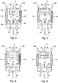
- FIGS 6 to 9 A first embodiment of the invention is illustrated in Figures 6 to 9 .
- These figures represent a pressure swing adsorption fluid treatment plant comprising a first and a second adsorber 1a, 1b, each having an adsorbent bed capable of separating oxygen from the air. Since the air consists essentially of oxygen and nitrogen, the adsorbent bed is used to trap nitrogen in order to increase the oxygen concentration. More particularly, the adsorbent bed is a molecular sieve consisting of zeolite beads.
- Each adsorber 1a, 1b has a feed inlet 2a, 2b connected to an air supply pipe 3 via a so-called supply solenoid valve 4a, 4b and an extraction outlet 5a, 5b of the oxygen produced, connected to a discharge pipe 6 via a discharge solenoid valve 7a, 7b.
- Each inlet 2a, 2b adsorbers 1a, 1b is further connected to a muffler purge or extraction 8 via a solenoid valve 9a, 9b called regeneration.
- outlets 5a, 5b of the adsorbers 1a, 1b are interconnected via a first connecting pipe 10 equipped with an adjustable flow restrictor 11, and a second connecting pipe 12 equipped with a balancing valve 13.
- a pressure sensor 14a, 14b makes it possible to measure the pressure at each of the outlets 5a, 5b of the adsorbers 1a, 1b.
- valves 4a and 9b are open and the valves 4b, 9a and 13 are closed.
- the pressurized air is fed through the air supply pipe 3 , passes through the supply valve 4a associated with the first adsorber 1a, and enters the latter so that the oxygen contained in the air is separated from the nitrogen and then rejected at the outlet 5a.
- the pressure P1 at the outlet 2a of the first adsorber 1a increases.
- the opening of the regeneration valve 9b allows the gas retained in the second adsorber 1b to escape suddenly through the purge silencer 8.
- the pressure in the second adsorber 1b typically ranges from about 2.5 bar to 0.degree. bar in a fraction of a second, which allows to desorb the nitrogen trapped in the adsorbent bed.
- the second adsorber 1b is flushed with a stream of oxygen from the bond 10 between the outlets 5a and 5b of the first and second adsorbers 1a and 1b to complete the desorption of nitrogen.
- this stream of oxygen remains minimal because of the presence of a flow restrictor 11.
- the value of the pressure P1 is stored, the valve 7a is open and the valves 4a and 9b are closed, as shown in FIG. figure 7 .
- the oxygen produced by the first adsorber 1a then passes through the valve 7a and enters said discharge pipe 6, the latter supplying for example an oxygen distribution network (not shown). This is the oxygen production step using the first adsorber 1a.
- ⁇ P is a predetermined pressure difference, calculated as a function of the maximum flow rate that can be provided by the adsorber.
- P1 is of the order of 5.2 bars and P3 is of the order of 4.8.
- the production step is limited by two pressure values, namely P1 and P3, and the pressure drop ⁇ P between these two values makes it possible to set a constant volume of production at each cycle and for each adsorber.
- a maximum production flow rate is therefore imposed, which makes it possible to control the concentration of oxygen produced.
- it is sufficient to increase the value of the pressure drop ⁇ P, and conversely to reduce it.
- This step is the step of slow pressurization of the second adsorber 1b.
- the equilibration valve 13 is opened, so as to balance the pressures between the two adsorbers 1a, 1b, typically of the order of 2.5 bars. This is the balancing step.
- the valves 4b and 9a are open and the balancing valve 13 is closed, so as to saturate the second adsorber 1b and, in parallel, the purge of the first adsorber.
- the cycle continues with the successive stages of oxygen production using the second adsorber 1b, slow pressurization of the first adsorber 1a and balancing.
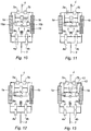
- a second embodiment of the invention is shown in Figures 10 to 13 .
- This embodiment differs from the first only in that the pressure sensors 14a and 14b have been replaced by a single pressure sensor 15, measuring the pressure at each of the ends of the connecting branch 10, on the one hand and on the other side. other of the flow restrictor.
- Solenoid valves 16a, 16b are arranged on either side of the pressure sensor 15.
- valves 16a, 16b Only one of the valves 16a, 16b is open, the other being closed.
- valve 16a is open and the valve 16b is closed so that the pressure at the outlet 5a of the adsorber 1a can be measured.
- the pressure at the outlet 5b of the adsorber 1b can be measured.
- This embodiment therefore makes it possible to replace the use of two separate sensors by the use of a single pressure sensor, able to measure the outlet pressures of each of the adsorbers 1a and 1b, depending on the state of the valves. 16a and 16b.
- a flowmeter mounted on the discharge pipe, can be used to determine the flow rate produced by each of the adsorbers.
Landscapes
- Chemical & Material Sciences (AREA)
- Engineering & Computer Science (AREA)
- Analytical Chemistry (AREA)
- General Chemical & Material Sciences (AREA)
- Oil, Petroleum & Natural Gas (AREA)
- Chemical Kinetics & Catalysis (AREA)
- Separation Of Gases By Adsorption (AREA)
Claims (7)
- Fluidbehandlungsverfahren durch Adsorption mit Druckvariation, dadurch gekennzeichnet, dass es auf zyklische Weise durchgeführt wird, wobei jeder Zyklus mindestens die folgenden Schritte umfasst, bestehend aus:- Versorgen mit Fluid eines ersten Adsorbers (1a), enthaltend ein Adsorptionsmittelbett, das ausgelegt ist, um den Sauerstoff von dem Fluid zu trennen, wobei der erste Adsorber (1a) einen Eingang (2a) zur Versorgung mit Fluid und einen Ausgang (5a) zur Extraktion von Sauerstoff umfasst,- Beenden der Versorgung mit Fluid des ersten Adsorbers (1a),- Versorgen einer Abführleitung (6) mit Sauerstoff, erzeugt durch den ersten Adsorber (1a), und Messen, mit Hilfe eines repräsentativen Parameters des Durchsatzes (P1, P3), des Sauerstoffdurchsatzes, extrahiert aus dem ersten Adsorber (1a),- Beenden der Extraktion von Sauerstoff des ersten Adsorbers (1a), wenn der extrahierte Durchsatz einen vorbestimmten Wert übersteigt,- Spülen des Fluids, das im ersten Adsorber (1a) verbleibt,- Versorgen eines zweiten Adsorbers (1b), enthaltend ein Adsorptionsbett, das ausgelegt ist, um den Sauerstoff von dem Fluid zu trennen, wobei der zweite Adsorber (1b) einen Eingang (2b) zur Versorgung mit Fluid und einen Ausgang (5b) zur Extraktion von Sauerstoff umfasst;- Beenden der Versorgung von Fluid des zweiten Adsorbers (1b),- Versorgen einer Abführleitung (6) mit dem Sauerstoff, erzeugt durch den zweiten Adsorber (1b), und Messen, mit Hilfe eines repräsentativen Parameters des Durchsatzes (P1, P3), des Sauerstoffdurchsatzes, extrahiert aus dem zweiten Adsorber (1b),- Beenden der Extraktion von Sauerstoff des zweiten Adsorbers (1b), wenn der extrahierte Durchsatz einen vorbestimmten Wert übersteigt,- Spülen des Fluids, das im zweiten Adsorber (1b) verbleibt,
wobei die Extraktionsausgänge (5a, 5b) des ersten und des zweiten Adsorbers (1a, 1b) miteinander mit Hilfe einer Verbindungsleitung (10) während der gesamten Dauer des Zyklus verbunden sind. - Verfahren nach Anspruch 1, dadurch gekennzeichnet, dass der Sauerstoffdurchsatz aus dem ersten (1a) bzw. zweiten Adsorber (1b) mit Hilfe eines Drucksensors (14a, 14b) auf der Ebene des Extraktionsausgangs (5a, 5b) des ersten Adsorbers (1a) bzw. des zweiten Adsorbers (1b) gemessen wird.
- Verfahren nach Anspruch 1, dadurch gekennzeichnet, dass der Sauerstoffdurchsatz aus dem ersten (1a) bzw. zweiten Adsorber (1b) mit Hilfe eines Durchsatzmessers auf der Ebene der Abführleitung (6) gemessen wird.
- Verfahren nach einem der Ansprüche 1 bis 3, dadurch gekennzeichnet, dass das Fluid, das in der Verbindungsleitung zirkuliert, Mittel zur Begrenzung des Durchsatzes (8) durchquert.
- Verfahren nach Anspruch 4, wenn es nicht von Anspruch 2 und 3 abhängt, dadurch gekennzeichnet, dass der Sauerstoffdurchsatz aus dem ersten (1a) bzw. zweiten Adsorber (1b) mit Hilfe eines einzigen Drucksensors (15) gemessen wird, der angeordnet ist, um alternativ entweder mit dem Extraktionsausgang (5a) des ersten Adsorbers (1a) oder mit dem Extraktionsausgang (5b) des zweiten Adsorbers (1b) verbunden zu sein.
- Verfahren nach einem der Ansprüche 1 bis 5, dadurch gekennzeichnet, dass die Extraktion von Sauerstoff aus dem ersten (1a) bzw. zweiten Adsorber (1b) beendet wird, wenn die Dauer der Extraktion einen vorbestimmten Wert übersteigt.
- Verfahren nach einem der Ansprüche 1 bis 6, dadurch gekennzeichnet, dass die Versorgung mit Fluid des ersten Adsorbers (1a) bzw. des zweiten Adsorbers (1b) beendet wird, wenn die Dauer der Versorgung einen vorbestimmten Wert übersteigt.
Applications Claiming Priority (1)
| Application Number | Priority Date | Filing Date | Title |
|---|---|---|---|
| FR0806099A FR2937878B1 (fr) | 2008-11-03 | 2008-11-03 | Procede de traitement de fluide par adsorption a variation de pression et installation correspondante |
Publications (2)
| Publication Number | Publication Date |
|---|---|
| EP2181752A1 EP2181752A1 (de) | 2010-05-05 |
| EP2181752B1 true EP2181752B1 (de) | 2017-02-08 |
Family
ID=40673424
Family Applications (1)
| Application Number | Title | Priority Date | Filing Date |
|---|---|---|---|
| EP09173745.2A Active EP2181752B1 (de) | 2008-11-03 | 2009-10-22 | Verfahren zur Behandlung von Fluiden mittels Druck-Wechsel-Adsorption |
Country Status (3)
| Country | Link |
|---|---|
| EP (1) | EP2181752B1 (de) |
| DK (1) | DK2181752T3 (de) |
| FR (1) | FR2937878B1 (de) |
Cited By (1)
| Publication number | Priority date | Publication date | Assignee | Title |
|---|---|---|---|---|
| CN106742890A (zh) * | 2017-01-10 | 2017-05-31 | 苏州苏净保护气氛有限公司 | 一种油气回收装置的安全监控系统及其控制方法 |
Families Citing this family (2)
| Publication number | Priority date | Publication date | Assignee | Title |
|---|---|---|---|---|
| DE102014017600A1 (de) | 2014-11-27 | 2016-06-02 | Linde Aktiengesellschaft | Verfahren und Vorrichtung zur Mengen- und Reinheitskontrolle bei Druckwechseladsorptionsanlagen |
| CN112320763B (zh) * | 2020-09-29 | 2022-08-16 | 杭州博大净化设备有限公司 | 一种psa制氧装置 |
Citations (1)
| Publication number | Priority date | Publication date | Assignee | Title |
|---|---|---|---|---|
| EP2093188A2 (de) * | 2008-02-22 | 2009-08-26 | Delphi Technologies, Inc. | Verfahren zum Erzeugen eines mit Sauerstoff angereicherten Gases für einen Benutzer |
Family Cites Families (7)
| Publication number | Priority date | Publication date | Assignee | Title |
|---|---|---|---|---|
| US4802899A (en) * | 1987-09-21 | 1989-02-07 | Airsep Corporation | Pressure swing adsorption apparatus |
| JP2004148258A (ja) * | 2002-10-31 | 2004-05-27 | Tokico Ltd | 気体分離装置 |
| DE10323137B4 (de) * | 2003-05-22 | 2008-04-30 | DRäGER AEROSPACE GMBH | Vorrichtung zur Anreicherung von Luft mit Sauerstoff in einem Flugzeug und einem Verfahren zum Betreiben der Vorrichtung |
| JP4739662B2 (ja) * | 2003-09-09 | 2011-08-03 | 帝人株式会社 | 酸素濃縮機 |
| EP1804874A2 (de) * | 2004-10-12 | 2007-07-11 | Airsep Corporation | Sauerstoffkonzentrator mit variabler temperatur und druckmesskontrolle |
| US7857894B2 (en) * | 2006-10-10 | 2010-12-28 | Inogen, Inc. | Adsorbent bed pressure balancing for a gas concentrator |
| JP4798016B2 (ja) * | 2007-02-09 | 2011-10-19 | ダイキン工業株式会社 | 酸素濃縮装置 |
-
2008
- 2008-11-03 FR FR0806099A patent/FR2937878B1/fr active Active
-
2009
- 2009-10-22 EP EP09173745.2A patent/EP2181752B1/de active Active
- 2009-10-22 DK DK09173745.2T patent/DK2181752T3/en active
Patent Citations (1)
| Publication number | Priority date | Publication date | Assignee | Title |
|---|---|---|---|---|
| EP2093188A2 (de) * | 2008-02-22 | 2009-08-26 | Delphi Technologies, Inc. | Verfahren zum Erzeugen eines mit Sauerstoff angereicherten Gases für einen Benutzer |
Cited By (2)
| Publication number | Priority date | Publication date | Assignee | Title |
|---|---|---|---|---|
| CN106742890A (zh) * | 2017-01-10 | 2017-05-31 | 苏州苏净保护气氛有限公司 | 一种油气回收装置的安全监控系统及其控制方法 |
| CN106742890B (zh) * | 2017-01-10 | 2018-08-10 | 苏州苏净保护气氛有限公司 | 一种油气回收装置的安全监控系统及其控制方法 |
Also Published As
| Publication number | Publication date |
|---|---|
| EP2181752A1 (de) | 2010-05-05 |
| DK2181752T3 (en) | 2017-05-22 |
| FR2937878B1 (fr) | 2011-04-15 |
| FR2937878A1 (fr) | 2010-05-07 |
Similar Documents
| Publication | Publication Date | Title |
|---|---|---|
| EP1374973A1 (de) | Verfahren zur Regelung einer Vorrichtung zur Behandlung einer Gascharge durch Druckwechseladsorption | |
| EP0948989A1 (de) | Verfahren und Vorrichtung zur Produktion von Sauerstoff durch Adsorption mit kurzem Zyklus | |
| EP2340102B1 (de) | Verfahren zur herstellung von grossen radialadsorbern | |
| FR2776939A1 (fr) | Procede de production d'oxygene par adsorption a variation de pression transatmospherique | |
| EP0988883B1 (de) | Verfahren zur Behandlung von Gasen mittels Druckwechseladsorption mit variabler Produktion | |
| EP2181752A1 (de) | Verfahren zur Behandlung von Fluiden mittels Druck-Wechsel-Adsorption und entsprechende Anlage | |
| EP1458461A1 (de) | Verfahren zur behandlung eines gasgemisches durch adsorption | |
| EP0864818B1 (de) | Verfahren und Vorrichtung zur Erzeugung von Luft medizinischer Qualität | |
| CA2801838C (fr) | Procede de pilotage d'une installation de production sur site de gaz medical et installation associee | |
| CA2801780A1 (fr) | Installation de production sur site de gaz medical et procede de pilotage associe | |
| FR2792848A1 (fr) | Appareil separateur de gaz pour le traitement de liquides charges de gaz dissous et installation de distribution de carburant equipee d'un tel systeme et procede de mise en oeuvre | |
| EP1347817A1 (de) | Verfahren und vorrichtung zur behandlung von gas durch adsorption | |
| EP0923977B1 (de) | Verfahren zur Gastrennung durch Adsorption mit variabler Produktionsrate | |
| FR2833861A1 (fr) | Dispositif de stockage et de melange de deux gaz | |
| EP0978305B1 (de) | Verfahren zur Trennung von Gasgemischen mittels Druckwechseladsorption | |
| FR2937879A1 (fr) | Procede de traitement de fluide par adsorption a variation de pression et installation correspondante | |
| EP0940164A1 (de) | Verfahren und Vorrichtung zur Trennung einer Gasmischung durch Adsorption | |
| EP2868361B1 (de) | System und Verfahren zum Umschalten der Flussrichtung eines Fluids in einem Fluidkreislauf, und mit diesem System ausgestatteter Fluidkreislauf | |
| EP0868936B1 (de) | Verfahren und Vorrichtung zur Trennung einer Gasmischung durch Adsorption | |
| FR2982949A1 (fr) | Dispositif pour la mesure de la permeabilite de bouchons de bouteilles et methode correspondante | |
| FR2779070A1 (fr) | Dispositif de fourniture d'un gaz epure a une installation purgee avec ce gaz epure | |
| EP1954377B1 (de) | Verfahren zur regelung einer anlage für die absorptionsbehandlung eines gases | |
| FR2982950A1 (fr) | Cellule pour la mesure de la permeabilite de bouchons | |
| FR2877229A1 (fr) | Procede de surveillance de soupape d'un doseur d'anesthesique | |
| FR2870840A1 (fr) | Procede pour exploiter une installation de decomposition de l'air en vue de la production d'oxygene a bord d'un avion ou autre aeronef et installation de decomposition de l'air pour sa mise en oeuvre |
Legal Events
| Date | Code | Title | Description |
|---|---|---|---|
| PUAI | Public reference made under article 153(3) epc to a published international application that has entered the european phase |
Free format text: ORIGINAL CODE: 0009012 |
|
| AK | Designated contracting states |
Kind code of ref document: A1 Designated state(s): AT BE BG CH CY CZ DE DK EE ES FI FR GB GR HR HU IE IS IT LI LT LU LV MC MK MT NL NO PL PT RO SE SI SK SM TR |
|
| AX | Request for extension of the european patent |
Extension state: AL BA RS |
|
| 17P | Request for examination filed |
Effective date: 20100705 |
|
| 17Q | First examination report despatched |
Effective date: 20100910 |
|
| GRAP | Despatch of communication of intention to grant a patent |
Free format text: ORIGINAL CODE: EPIDOSNIGR1 |
|
| RIC1 | Information provided on ipc code assigned before grant |
Ipc: B01D 53/04 20060101ALN20160831BHEP Ipc: B01D 53/047 20060101AFI20160831BHEP |
|
| INTG | Intention to grant announced |
Effective date: 20160919 |
|
| GRAS | Grant fee paid |
Free format text: ORIGINAL CODE: EPIDOSNIGR3 |
|
| GRAA | (expected) grant |
Free format text: ORIGINAL CODE: 0009210 |
|
| AK | Designated contracting states |
Kind code of ref document: B1 Designated state(s): AT BE BG CH CY CZ DE DK EE ES FI FR GB GR HR HU IE IS IT LI LT LU LV MC MK MT NL NO PL PT RO SE SI SK SM TR |
|
| REG | Reference to a national code |
Ref country code: GB Ref legal event code: FG4D Free format text: NOT ENGLISH |
|
| REG | Reference to a national code |
Ref country code: CH Ref legal event code: EP Ref country code: AT Ref legal event code: REF Ref document number: 866616 Country of ref document: AT Kind code of ref document: T Effective date: 20170215 |
|
| REG | Reference to a national code |
Ref country code: IE Ref legal event code: FG4D Free format text: LANGUAGE OF EP DOCUMENT: FRENCH |
|
| REG | Reference to a national code |
Ref country code: DE Ref legal event code: R096 Ref document number: 602009044102 Country of ref document: DE |
|
| REG | Reference to a national code |
Ref country code: DK Ref legal event code: T3 Effective date: 20170516 |
|
| REG | Reference to a national code |
Ref country code: LT Ref legal event code: MG4D |
|
| REG | Reference to a national code |
Ref country code: NL Ref legal event code: MP Effective date: 20170208 |
|
| REG | Reference to a national code |
Ref country code: AT Ref legal event code: MK05 Ref document number: 866616 Country of ref document: AT Kind code of ref document: T Effective date: 20170208 |
|
| PG25 | Lapsed in a contracting state [announced via postgrant information from national office to epo] |
Ref country code: FI Free format text: LAPSE BECAUSE OF FAILURE TO SUBMIT A TRANSLATION OF THE DESCRIPTION OR TO PAY THE FEE WITHIN THE PRESCRIBED TIME-LIMIT Effective date: 20170208 Ref country code: HR Free format text: LAPSE BECAUSE OF FAILURE TO SUBMIT A TRANSLATION OF THE DESCRIPTION OR TO PAY THE FEE WITHIN THE PRESCRIBED TIME-LIMIT Effective date: 20170208 Ref country code: GR Free format text: LAPSE BECAUSE OF FAILURE TO SUBMIT A TRANSLATION OF THE DESCRIPTION OR TO PAY THE FEE WITHIN THE PRESCRIBED TIME-LIMIT Effective date: 20170509 Ref country code: LT Free format text: LAPSE BECAUSE OF FAILURE TO SUBMIT A TRANSLATION OF THE DESCRIPTION OR TO PAY THE FEE WITHIN THE PRESCRIBED TIME-LIMIT Effective date: 20170208 Ref country code: NO Free format text: LAPSE BECAUSE OF FAILURE TO SUBMIT A TRANSLATION OF THE DESCRIPTION OR TO PAY THE FEE WITHIN THE PRESCRIBED TIME-LIMIT Effective date: 20170508 |
|
| PG25 | Lapsed in a contracting state [announced via postgrant information from national office to epo] |
Ref country code: BG Free format text: LAPSE BECAUSE OF FAILURE TO SUBMIT A TRANSLATION OF THE DESCRIPTION OR TO PAY THE FEE WITHIN THE PRESCRIBED TIME-LIMIT Effective date: 20170508 Ref country code: LV Free format text: LAPSE BECAUSE OF FAILURE TO SUBMIT A TRANSLATION OF THE DESCRIPTION OR TO PAY THE FEE WITHIN THE PRESCRIBED TIME-LIMIT Effective date: 20170208 Ref country code: SE Free format text: LAPSE BECAUSE OF FAILURE TO SUBMIT A TRANSLATION OF THE DESCRIPTION OR TO PAY THE FEE WITHIN THE PRESCRIBED TIME-LIMIT Effective date: 20170208 Ref country code: NL Free format text: LAPSE BECAUSE OF FAILURE TO SUBMIT A TRANSLATION OF THE DESCRIPTION OR TO PAY THE FEE WITHIN THE PRESCRIBED TIME-LIMIT Effective date: 20170208 Ref country code: AT Free format text: LAPSE BECAUSE OF FAILURE TO SUBMIT A TRANSLATION OF THE DESCRIPTION OR TO PAY THE FEE WITHIN THE PRESCRIBED TIME-LIMIT Effective date: 20170208 Ref country code: ES Free format text: LAPSE BECAUSE OF FAILURE TO SUBMIT A TRANSLATION OF THE DESCRIPTION OR TO PAY THE FEE WITHIN THE PRESCRIBED TIME-LIMIT Effective date: 20170208 Ref country code: PT Free format text: LAPSE BECAUSE OF FAILURE TO SUBMIT A TRANSLATION OF THE DESCRIPTION OR TO PAY THE FEE WITHIN THE PRESCRIBED TIME-LIMIT Effective date: 20170608 |
|
| REG | Reference to a national code |
Ref country code: FR Ref legal event code: PLFP Year of fee payment: 9 |
|
| PG25 | Lapsed in a contracting state [announced via postgrant information from national office to epo] |
Ref country code: SK Free format text: LAPSE BECAUSE OF FAILURE TO SUBMIT A TRANSLATION OF THE DESCRIPTION OR TO PAY THE FEE WITHIN THE PRESCRIBED TIME-LIMIT Effective date: 20170208 Ref country code: EE Free format text: LAPSE BECAUSE OF FAILURE TO SUBMIT A TRANSLATION OF THE DESCRIPTION OR TO PAY THE FEE WITHIN THE PRESCRIBED TIME-LIMIT Effective date: 20170208 Ref country code: RO Free format text: LAPSE BECAUSE OF FAILURE TO SUBMIT A TRANSLATION OF THE DESCRIPTION OR TO PAY THE FEE WITHIN THE PRESCRIBED TIME-LIMIT Effective date: 20170208 Ref country code: CZ Free format text: LAPSE BECAUSE OF FAILURE TO SUBMIT A TRANSLATION OF THE DESCRIPTION OR TO PAY THE FEE WITHIN THE PRESCRIBED TIME-LIMIT Effective date: 20170208 |
|
| REG | Reference to a national code |
Ref country code: DE Ref legal event code: R097 Ref document number: 602009044102 Country of ref document: DE |
|
| PG25 | Lapsed in a contracting state [announced via postgrant information from national office to epo] |
Ref country code: PL Free format text: LAPSE BECAUSE OF FAILURE TO SUBMIT A TRANSLATION OF THE DESCRIPTION OR TO PAY THE FEE WITHIN THE PRESCRIBED TIME-LIMIT Effective date: 20170208 Ref country code: SM Free format text: LAPSE BECAUSE OF FAILURE TO SUBMIT A TRANSLATION OF THE DESCRIPTION OR TO PAY THE FEE WITHIN THE PRESCRIBED TIME-LIMIT Effective date: 20170208 |
|
| PLBE | No opposition filed within time limit |
Free format text: ORIGINAL CODE: 0009261 |
|
| STAA | Information on the status of an ep patent application or granted ep patent |
Free format text: STATUS: NO OPPOSITION FILED WITHIN TIME LIMIT |
|
| 26N | No opposition filed |
Effective date: 20171109 |
|
| PG25 | Lapsed in a contracting state [announced via postgrant information from national office to epo] |
Ref country code: SI Free format text: LAPSE BECAUSE OF FAILURE TO SUBMIT A TRANSLATION OF THE DESCRIPTION OR TO PAY THE FEE WITHIN THE PRESCRIBED TIME-LIMIT Effective date: 20170208 |
|
| PG25 | Lapsed in a contracting state [announced via postgrant information from national office to epo] |
Ref country code: MC Free format text: LAPSE BECAUSE OF FAILURE TO SUBMIT A TRANSLATION OF THE DESCRIPTION OR TO PAY THE FEE WITHIN THE PRESCRIBED TIME-LIMIT Effective date: 20170208 |
|
| REG | Reference to a national code |
Ref country code: CH Ref legal event code: PL |
|
| GBPC | Gb: european patent ceased through non-payment of renewal fee |
Effective date: 20171022 |
|
| REG | Reference to a national code |
Ref country code: IE Ref legal event code: MM4A |
|
| PG25 | Lapsed in a contracting state [announced via postgrant information from national office to epo] |
Ref country code: LI Free format text: LAPSE BECAUSE OF NON-PAYMENT OF DUE FEES Effective date: 20171031 Ref country code: LU Free format text: LAPSE BECAUSE OF NON-PAYMENT OF DUE FEES Effective date: 20171022 Ref country code: CH Free format text: LAPSE BECAUSE OF NON-PAYMENT OF DUE FEES Effective date: 20171031 Ref country code: GB Free format text: LAPSE BECAUSE OF NON-PAYMENT OF DUE FEES Effective date: 20171022 |
|
| REG | Reference to a national code |
Ref country code: BE Ref legal event code: MM Effective date: 20171031 |
|
| PG25 | Lapsed in a contracting state [announced via postgrant information from national office to epo] |
Ref country code: BE Free format text: LAPSE BECAUSE OF NON-PAYMENT OF DUE FEES Effective date: 20171031 |
|
| REG | Reference to a national code |
Ref country code: FR Ref legal event code: PLFP Year of fee payment: 10 |
|
| PG25 | Lapsed in a contracting state [announced via postgrant information from national office to epo] |
Ref country code: MT Free format text: LAPSE BECAUSE OF FAILURE TO SUBMIT A TRANSLATION OF THE DESCRIPTION OR TO PAY THE FEE WITHIN THE PRESCRIBED TIME-LIMIT Effective date: 20170208 |
|
| PG25 | Lapsed in a contracting state [announced via postgrant information from national office to epo] |
Ref country code: IE Free format text: LAPSE BECAUSE OF NON-PAYMENT OF DUE FEES Effective date: 20171022 |
|
| PG25 | Lapsed in a contracting state [announced via postgrant information from national office to epo] |
Ref country code: HU Free format text: LAPSE BECAUSE OF FAILURE TO SUBMIT A TRANSLATION OF THE DESCRIPTION OR TO PAY THE FEE WITHIN THE PRESCRIBED TIME-LIMIT; INVALID AB INITIO Effective date: 20091022 |
|
| PG25 | Lapsed in a contracting state [announced via postgrant information from national office to epo] |
Ref country code: CY Free format text: LAPSE BECAUSE OF NON-PAYMENT OF DUE FEES Effective date: 20170208 |
|
| PG25 | Lapsed in a contracting state [announced via postgrant information from national office to epo] |
Ref country code: MK Free format text: LAPSE BECAUSE OF FAILURE TO SUBMIT A TRANSLATION OF THE DESCRIPTION OR TO PAY THE FEE WITHIN THE PRESCRIBED TIME-LIMIT Effective date: 20170208 |
|
| PG25 | Lapsed in a contracting state [announced via postgrant information from national office to epo] |
Ref country code: TR Free format text: LAPSE BECAUSE OF FAILURE TO SUBMIT A TRANSLATION OF THE DESCRIPTION OR TO PAY THE FEE WITHIN THE PRESCRIBED TIME-LIMIT Effective date: 20170208 |
|
| PG25 | Lapsed in a contracting state [announced via postgrant information from national office to epo] |
Ref country code: IS Free format text: LAPSE BECAUSE OF FAILURE TO SUBMIT A TRANSLATION OF THE DESCRIPTION OR TO PAY THE FEE WITHIN THE PRESCRIBED TIME-LIMIT Effective date: 20170608 |
|
| PGFP | Annual fee paid to national office [announced via postgrant information from national office to epo] |
Ref country code: FR Payment date: 20250731 Year of fee payment: 17 |
|
| PGFP | Annual fee paid to national office [announced via postgrant information from national office to epo] |
Ref country code: DE Payment date: 20250829 Year of fee payment: 17 |
|
| PGFP | Annual fee paid to national office [announced via postgrant information from national office to epo] |
Ref country code: DK Payment date: 20251021 Year of fee payment: 17 Ref country code: IT Payment date: 20251013 Year of fee payment: 17 |