EP2181864A1 - Luftreifen für ein Motorrad - Google Patents
Luftreifen für ein Motorrad Download PDFInfo
- Publication number
- EP2181864A1 EP2181864A1 EP09009429A EP09009429A EP2181864A1 EP 2181864 A1 EP2181864 A1 EP 2181864A1 EP 09009429 A EP09009429 A EP 09009429A EP 09009429 A EP09009429 A EP 09009429A EP 2181864 A1 EP2181864 A1 EP 2181864A1
- Authority
- EP
- European Patent Office
- Prior art keywords
- region
- tilt angle
- center
- tread
- tire
- Prior art date
- Legal status (The legal status is an assumption and is not a legal conclusion. Google has not performed a legal analysis and makes no representation as to the accuracy of the status listed.)
- Granted
Links
- 235000019589 hardness Nutrition 0.000 claims description 67
- 238000011156 evaluation Methods 0.000 description 46
- 230000001052 transient effect Effects 0.000 description 21
- 239000000835 fiber Substances 0.000 description 10
- 239000011324 bead Substances 0.000 description 6
- 238000002474 experimental method Methods 0.000 description 6
- 239000000463 material Substances 0.000 description 6
- 230000007704 transition Effects 0.000 description 6
- 230000000052 comparative effect Effects 0.000 description 5
- 239000000203 mixture Substances 0.000 description 4
- 238000006243 chemical reaction Methods 0.000 description 3
- 241000254043 Melolonthinae Species 0.000 description 2
- 229920000297 Rayon Polymers 0.000 description 2
- 229920006231 aramid fiber Polymers 0.000 description 2
- 230000008859 change Effects 0.000 description 2
- 238000006073 displacement reaction Methods 0.000 description 2
- 230000006872 improvement Effects 0.000 description 2
- 229920001778 nylon Polymers 0.000 description 2
- 230000002093 peripheral effect Effects 0.000 description 2
- 229920003207 poly(ethylene-2,6-naphthalate) Polymers 0.000 description 2
- 229920000728 polyester Polymers 0.000 description 2
- -1 polyethylene naphthalate Polymers 0.000 description 2
- 239000011112 polyethylene naphthalate Substances 0.000 description 2
- 239000002964 rayon Substances 0.000 description 2
- 230000004043 responsiveness Effects 0.000 description 2
- 229910000831 Steel Inorganic materials 0.000 description 1
- 238000010521 absorption reaction Methods 0.000 description 1
- 238000005259 measurement Methods 0.000 description 1
- 230000009467 reduction Effects 0.000 description 1
- 230000004044 response Effects 0.000 description 1
- 230000035939 shock Effects 0.000 description 1
- 239000010959 steel Substances 0.000 description 1
Images




Classifications
-
- B—PERFORMING OPERATIONS; TRANSPORTING
- B60—VEHICLES IN GENERAL
- B60C—VEHICLE TYRES; TYRE INFLATION; TYRE CHANGING; CONNECTING VALVES TO INFLATABLE ELASTIC BODIES IN GENERAL; DEVICES OR ARRANGEMENTS RELATED TO TYRES
- B60C11/00—Tyre tread bands; Tread patterns; Anti-skid inserts
- B60C11/03—Tread patterns
- B60C11/0306—Patterns comprising block rows or discontinuous ribs
- B60C11/0309—Patterns comprising block rows or discontinuous ribs further characterised by the groove cross-section
-
- B—PERFORMING OPERATIONS; TRANSPORTING
- B60—VEHICLES IN GENERAL
- B60C—VEHICLE TYRES; TYRE INFLATION; TYRE CHANGING; CONNECTING VALVES TO INFLATABLE ELASTIC BODIES IN GENERAL; DEVICES OR ARRANGEMENTS RELATED TO TYRES
- B60C11/00—Tyre tread bands; Tread patterns; Anti-skid inserts
- B60C11/0041—Tyre tread bands; Tread patterns; Anti-skid inserts comprising different tread rubber layers
- B60C11/005—Tyre tread bands; Tread patterns; Anti-skid inserts comprising different tread rubber layers with cap and base layers
- B60C11/0058—Tyre tread bands; Tread patterns; Anti-skid inserts comprising different tread rubber layers with cap and base layers with different cap rubber layers in the axial direction
-
- B—PERFORMING OPERATIONS; TRANSPORTING
- B60—VEHICLES IN GENERAL
- B60C—VEHICLE TYRES; TYRE INFLATION; TYRE CHANGING; CONNECTING VALVES TO INFLATABLE ELASTIC BODIES IN GENERAL; DEVICES OR ARRANGEMENTS RELATED TO TYRES
- B60C11/00—Tyre tread bands; Tread patterns; Anti-skid inserts
- B60C11/03—Tread patterns
- B60C11/0311—Patterns comprising tread lugs arranged parallel or oblique to the axis of rotation
-
- B—PERFORMING OPERATIONS; TRANSPORTING
- B60—VEHICLES IN GENERAL
- B60C—VEHICLE TYRES; TYRE INFLATION; TYRE CHANGING; CONNECTING VALVES TO INFLATABLE ELASTIC BODIES IN GENERAL; DEVICES OR ARRANGEMENTS RELATED TO TYRES
- B60C11/00—Tyre tread bands; Tread patterns; Anti-skid inserts
- B60C11/03—Tread patterns
- B60C11/0311—Patterns comprising tread lugs arranged parallel or oblique to the axis of rotation
- B60C11/0316—Patterns comprising tread lugs arranged parallel or oblique to the axis of rotation further characterised by the groove cross-section
-
- B—PERFORMING OPERATIONS; TRANSPORTING
- B60—VEHICLES IN GENERAL
- B60C—VEHICLE TYRES; TYRE INFLATION; TYRE CHANGING; CONNECTING VALVES TO INFLATABLE ELASTIC BODIES IN GENERAL; DEVICES OR ARRANGEMENTS RELATED TO TYRES
- B60C11/00—Tyre tread bands; Tread patterns; Anti-skid inserts
- B60C11/03—Tread patterns
- B60C11/13—Tread patterns characterised by the groove cross-section, e.g. for buttressing or preventing stone-trapping
- B60C11/1307—Tread patterns characterised by the groove cross-section, e.g. for buttressing or preventing stone-trapping with special features of the groove walls
- B60C11/1323—Tread patterns characterised by the groove cross-section, e.g. for buttressing or preventing stone-trapping with special features of the groove walls asymmetric
-
- B—PERFORMING OPERATIONS; TRANSPORTING
- B60—VEHICLES IN GENERAL
- B60C—VEHICLE TYRES; TYRE INFLATION; TYRE CHANGING; CONNECTING VALVES TO INFLATABLE ELASTIC BODIES IN GENERAL; DEVICES OR ARRANGEMENTS RELATED TO TYRES
- B60C11/00—Tyre tread bands; Tread patterns; Anti-skid inserts
- B60C11/0008—Tyre tread bands; Tread patterns; Anti-skid inserts characterised by the tread rubber
- B60C2011/0016—Physical properties or dimensions
- B60C2011/0025—Modulus or tan delta
-
- B—PERFORMING OPERATIONS; TRANSPORTING
- B60—VEHICLES IN GENERAL
- B60C—VEHICLE TYRES; TYRE INFLATION; TYRE CHANGING; CONNECTING VALVES TO INFLATABLE ELASTIC BODIES IN GENERAL; DEVICES OR ARRANGEMENTS RELATED TO TYRES
- B60C2200/00—Tyres specially adapted for particular applications
- B60C2200/10—Tyres specially adapted for particular applications for motorcycles, scooters or the like
Definitions
- the present invention relates to a pneumatic tire to be attached to a motorcycle.
- the present invention relates to an improvement in a tread of a tire.
- a centrifugal force acts on the motorcycle.
- the cornering force is balanced with the centrifugal force.
- a rider tilts the motorcycle inward. By the tilt, the cornering of the motorcycle is achieved.
- a tire for the motorcycle includes a tread having a small radius of curvature.
- a center region of the tread comes in contact with a ground.
- a shoulder region comes in contact with the ground.
- a tire considering respective roles of the center region and the shoulder region has been described in Japanese Laid-Open Patent Publication No. 2005-271760 and Japanese Laid-Open Patent Publication No. 2008-143327 .
- a crosslinked rubber in a center region of a tread has a higher hardness than a crosslinked rubber in a shoulder region. Consequently, the tire has an excellent handling stability in straight running and has an excellent grip performance in cornering.
- a crosslinked rubber in a center region of a tread is set to have a lower hardness than a crosslinked rubber in a shoulder region.
- the center region having a low hardness in the tread comes in contact with a ground. Consequently, the tire is excellent in a disturbance absorption in the straight running.
- the shoulder region having a high hardness in the tread comes in contact with the ground. Consequently, a great camber thrust is generated.
- the tire has an excellent cornering performance. In the tire, a disturbance absorbing performance and a cornering performance in the straight running are compatible with each other.
- a groove is formed on a tread surface of a tire for a motorcycle.
- a tread pattern is formed.
- the tread pattern contributes to an enhancement in a draining property of the tire, an improvement in a braking performance, a reduction in a noise and the like.
- the tread pattern contributes to a fine sight of the tire.
- a difference is made in an amount of wear of a groove between the regions.
- the groove is formed from the region positioned on the center side of the tread to the region positioned on the tread end side.
- a difference is easily made in the amount of wear of the groove between the regions.
- partial wear is apt to occur.
- a tire for a motorcycle according to the present invention includes a tread divided into a plurality of regions in an axial direction.
- the tread has a region positioned on a center and at least one region positioned on an outside of the region in the axial direction.
- a rubber hardness H(n+1) of an (n+1)th region from the center is different from a rubber hardness Hn of an n-th region from the center when n is a natural number.
- the tread includes a groove.
- the groove has a wall surface.
- a minimum value of a tilt angle of the wall surface in the (n+1)th region from the center is different from that of the tilt angle in the n-th region from the center.
- a minimum value of a tilt angle of a wall surface in a region having a low rubber hardness is greater than that of a tilt angle of a wall surface in a region having a high rubber hardness.
- the rubber hardness H(n+1) of the (n+1)th region from the center is lower than the rubber hardness Hn of the n-th region from the center.
- the minimum value of the tilt angle of the wall surface in the (n+1)th region from the center is greater than that of the tilt angle in the n-th region from the center.
- the tread should include a groove provided across the (n+1)th region from the center and the n-th region from the center.
- the tread of the tire should have a groove provided from the region positioned on the center to a region positioned on a most tread end side.
- a rubber hardness of each of the regions present from the center to the tread end is lower than that of an adjacent region to the center side.
- a minimum value of a tilt angle of the same region is greater than that of the adjacent region to the center side.
- the (n+1)th region from the center should have a central portion positioned on a center in an axial direction of the region.
- a tilt angle ⁇ (n+1) of a wall surface of a groove in the central portion has a constant value.
- the n-th region from the center has a central portion positioned on a center in the axial direction of the same region.
- a tilt angle ⁇ (n) of a wall surface of a groove in the central portion has a constant value.
- the tilt angle ⁇ (n+1) is greater than the tilt angle ⁇ (n).
- the tilt angle of the wall surface is gradually increased from the tilt angle ⁇ (n) to the tilt angle ⁇ (n+1) between the central portion of the n-th region from the center and the central portion of the (n+1)th region from the center.
- the tread surface of the tire should have an early reaching portion and a late reaching portion along the groove.
- the early reaching portion is constituted to come in contact with a road surface earlier than the late reaching portion in a circumferential direction when a normal rotation is carried out.
- the groove has a pair of wall surfaces. The tilt angle is determined on any of the wall surfaces which is linked to the early reaching portion. It is preferable that the tire should be attached to a rear wheel of a motorcycle.
- the rubber hardness H(n+1) of the (n+1)th region from the center is higher than the rubber hardness Hn of the n-th region from the center.
- the minimum value of the tilt angle of the wall surface in the n-th region from the center is greater than that of the tilt angle in the (n+1)th region from the center.
- the tread surface of the tire should have an early reaching portion and a late reaching portion along the groove.
- the early reaching portion is constituted to come in contact with a road surface earlier than the late reaching portion in a circumferential direction when a normal rotation is carried out.
- the groove has a pair of wall surfaces. The tilt angle is determined on any of the wall surfaces which is linked to the late reaching portion. It is preferable that the tire should be attached to a front wheel of a motorcycle.
- the bead 8 is extended almost inward in the radial direction from the sidewall 6.
- the bead 8 includes a core 26 and an apex 28 extended outward in the radial direction from the core 26.
- the apex 28 is tapered outward in the radial direction.
- the apex 28 is formed by a crosslinked rubber composition.
- the apex 28 has a high hardness.
- a double arrow WE5 indicates a width in the axial direction of the end 64.
- a double arrow WE6 indicates a width in the axial direction of the end 66.
- the end widths WE5 and WE6 are measured along the tread surface 18.
- the end width WE5 is equal to the end width WE6.
- the groove 40 is also formed in the same manner as the groove 38.
- the groove 40 is formed across the second region 22 and the third region 24.
- a tilt angle of the wall surface in the central portion 56 of the second region 22 in the groove 40 is constant.
- a tilt angle of the wall surface in the central portion 62 of the third region 24 in the groove 40 is constant.
- the tilt angle of the central portion 62 is greater than that of the central portion 56.
- the tilt angle is gradually increased from the tilt angle of the central portion 56 to that of the central portion 62.
- the tilt angle is increased in a direction from the central portion 56 to the central portion 62.
- a rubber hardness of the first region 20 is higher than that of the second region 22. Therefore, the first region 20 is more excellent in a straight running stability and a wear resistance than the second region 22.
- the second region 22 is more excellent in a grip performance than the first region 20.
- the rubber hardness of the second region 22 is higher than that of the third region 24. Therefore, the second region 22 is more excellent in the straight running stability and the wear resistance than the third region 24.
- the third region 24 is more excellent in the grip performance than the second region 22.
- a rubber hardness of the region positioned on the center side is higher than that on the adjacent tread end side.
- a ratio (WC1 / WT1) of the width WC1 of the central portion to the width WT1 in the axial direction is 0.6.
- the tilt angle ⁇ 1 of the central portion 50 is constant. Therefore, the early reaching portion 74 is uniformly worn within a range of the width WC1 of the central portion. In the central portion 50, partial wear is prevented from occurring in the tread surface 18 around the groove 38. From this viewpoint, it is preferable that the ratio (WC1 / WT1) of the width WC1 of the central portion to the width WT1 in the axial direction should be equal to or higher than 0.5.
- the ratio (( ⁇ 2 - ⁇ 1) / (H1 - H2)) should be equal to or higher than 1.25.
- a ratio (( ⁇ 3 - ⁇ 2) / (H2 - H3)) is preferably equal to or higher than one and is further preferably equal to or higher than 1.25 in the second region 22 and the third region 24.
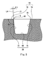
- Fig. 5 shows a section of the groove 38 in the first region 20.
- a point Q indicates a point of the edge 80 in the section of Fig. 5 .
- a line V-V forms a perpendicular section to the edge 80 as shown in Fig. 3 .
- a line L3 in Fig. 5 is a perpendicular to the tread surface 18 which passes through the point Q.
- a line L4 is an extended line of the wall surface 72 in the section of Fig. 5 .
- An angle ⁇ 1 is formed by the lines L3 and L4.
- the sidewall 86 is extended almost inward in the radial direction from an end of the tread 84.
- the bead 88 is extended almost inward in the radial direction from the sidewall 86.
- the bead 88 includes a core 106 and an apex 108 extended outward in the radial direction from the core 106.
- the belt 92 is positioned between the carcass 90 and the tread 84.
- the belt 92 is formed by a belt ply 116.
- the inner liner 94 is bonded to an inner peripheral surface of the carcass 90.
- the groove 118 is formed across the first region 100 positioned on the center and the second region 102 positioned on the tread end side.
- the groove 120 is formed across the first region 100 positioned on the center side and the second region 102 positioned on the tread end side.
- the first region 100 includes a central portion 130 and ends 132 and 134.
- the central portion 130 is positioned on a center in the axial direction of the first region 100.
- the end 132 is positioned on an outside in the axial direction of the central portion 130 and is linked to one of the second regions 102.
- the end 134 is positioned on the outside in the axial direction and is linked to the other second region 102.
- a double arrow WC1 indicates a width in the axial direction of the central portion 130.
- a double arrow WT1 indicates a width in the axial direction of the first region 100.
- a double arrow WE1 indicates a width in the axial direction of the end 132.
- a double arrow WE2 indicates a width in the axial direction of the end 134.
- the end widths WE1 and WE2 are equal to each other.
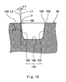
- Fig. 9 shows a section of the groove 118.
- the groove 118 includes a bottom surface 148, a wall surface 150 and a wall surface 152.
- the wall surfaces 150 and 152 are extended in a longitudinal direction of the groove 118.
- the wall surfaces 150 and 152 are erected from the bottom surface 148 and are linked to the tread surface 98.
- the tread surface 98 includes an early reaching portion 154, a late reaching portion 156, and edges 158 and 160.
- the early reaching portion 154 is an end of the tread surface 98 extended along the groove 118.
- the early reaching portion 154 is linked to the wall surface 150.
- the edge 158 is a segment for crossing the early reaching portion 154 of the tread surface 98 and the wall surface 150.
- a point Q indicates a point of the edge 160 in the section of Fig. 9 .
- a line IX-IX forms a perpendicular section to the edge 160 as shown in Fig. 8 .
- a line L3 in Fig. 9 is a perpendicular to the tread surface 98 which passes through the point Q.
- a line L4 is an extended line of the wall surface 152 in the section of Fig. 9 .
- An angle ⁇ 2 in Fig. 9 is formed by the lines L3 and L4. The angle ⁇ 2 is a tilt angle of the wall surface 152 in the groove 118.
- the groove 120 is also formed in the same manner as the groove 118.
- the groove 120 is formed across the first region 100 and the second region 102.
- a tilt angle of the wall surface in the central portion 130 of the first region 100 in the groove 120 is constant.
- a tilt angle of the wall surface in the central portion 136 of the second region 102 in the groove 120 is constant.
- the tilt angle of the central portion 130 is greater than that of the central portion 136.
- the tilt angle is gradually increased from the tilt angle of the central portion 136 to that of the central portion 130.
- the tilt angle is increased in a direction from the central portion 136 to the central portion 130.
- a rubber hardness of the second region 102 is higher than that of the first region 100. Therefore, a great camber thrust is obtained in the tire 82.
- the first region 100 is more excellent in a disturbance absorbing performance than the second region 102.
- a rubber hardness of the region positioned on the center side is lower than that of the region positioned on the adjacent tread end side. The region positioned on the center side is more excellent in the disturbance absorbing performance than the region positioned on the adjacent tread end side. The region positioned on the tread end side contributes to the generation of the great camber thrust. In the tire 82, thus, straight running and cornering performances are compatible with each other.
- a ratio (WC1 / WT1) of the width WC1 of the central portion to the width WT1 in the axial direction is 0. 6.
- the tilt angle ⁇ 1 of the central portion 130 is constant. Therefore, the late reaching portion 156 is uniformly worn within a range of the width WC1 of the central portion.
- partial wear is prevented from occurring in the tread surface 98 around the groove 118.
- the ratio (WC1 / WT1) of the width WC1 of the central portion to the width WT1 in the axial direction should be equal to or higher than 0.5.
- a ratio (WC2 / WT2) of the width WC2 of the central portion to the width WT2 in the axial direction should be equal to or higher than 0.5 in the second region 102.
- the tilt angle of the wall surface 152 of the groove 118 is gradually increased from the tilt angle ⁇ 2 to the tilt angle ⁇ 1 within a range of the ends 140 and 132. Therefore, a characteristic of the tread 84 can be prevented from being rapidly changed in a transition of a contact surface with a road surface between the first region 100 and the second region 102. More specifically, the tire 82 is excellent in a transient characteristic. From this viewpoint, it is preferable that the ratio (WC1 / WT1) of the width WC1 of the central portion to the width WT1 in the axial direction of the first region 100 should be equal to or lower than 0.8. From the same viewpoint, it is preferable that the ratio (WC2 / WT2) of the width WC2 of the central portion to the width WT2 in the axial direction of the second region 102 should be equal to or lower than 0.8.
- a variation in the tilt angle of the wall surface 152 linked to the late reaching portion 156 greatly contributes to the transient characteristic of the tire 82. From this viewpoint, it is preferable that the tilt angle of the wall surface of the groove 118 should be determined by the wall surface 152 linked to the late reaching portion 156.
- a ratio (( ⁇ 1 - ⁇ 2) / (H2 - H1)) of a difference ( ⁇ 1 - ⁇ 2) between the tilt angle ⁇ 1 of the first region 100 and the tilt angle ⁇ 2 of the second region 102 to a difference (H2 - H1) between a rubber hardness H2 of the second region 102 and a rubber hardness H1 of the first region 100 should be equal to or higher than one. It is further preferable that the ratio (( ⁇ 1 - ⁇ 2) / (H2 - H1)) should be equal to or higher than 1.25.
- a tilt angle ⁇ 2 of the central portion 136 is obtained in the same manner as the tilt angle ⁇ 1.
- the tilt angle ⁇ 2 is a constant angle.
- the tilt angle ⁇ 1 of the first region 100 is greater than the tilt angle ⁇ 2.
- the tilt angle is gradually increased from the tilt angle ⁇ 2 to the tilt angle ⁇ 1 in a direction from the central portion 136 to the central portion 130.
- the tilt angles ⁇ 1 and ⁇ 2 are further examples of tilt angles ⁇ 1 and ⁇ 2 of the wall surface of the groove according to the present invention.
- the first region 100 having a low hardness mainly comes in contact with the ground in the straight running.
- the tire 82 is excellent in a disturbance absorbing performance.
- the second region 102 having a high hardness mainly comes in contact with the ground.
- the second region 102 having a high rubber hardness H2 contributes to a generation of a great camber thrust.
- the tire 82 is excellent in a cornering performance.
- a motorcycle using the tire 82 for a front tire has straight running and cornering performances which can be compatible with each other. In the tire 82, furthermore, it is possible to prevent the partial wear of the tread surface 98 around the grooves 118, 120, 122 and 124 from occurring.
- a tire having a tread divided into at least five regions includes a groove provided from a region positioned on a center to a region positioned on a tread end side.
- a rubber hardness in each of the regions present from the center to the tread end is lower than that of an adjacent region to the tread end side.
- a minimum value of the tilt angle of the wall surface 152 is set to be greater than that of an adjacent region to the tread end side. It is further preferable that the minimum value of the tilt angle of the wall surface 150 should be set to be greater than that of the adjacent region to the tread end side.
- the rubber hardness is measured by pressing a Durometer of Type A against the tire 2 on a condition of 23°C in accordance with the regulations of "JIS-K 6253".
- the dimension and the angle of each member of the tire 2 or 82 are measured in a state in which the tire 2 or 82 is incorporated in a normal rim and is filled with air to obtain a normal internal pressure if there is no particular description. During the measurement, a load is not applied to the tire 2 or 82.
- the normal rim implies a rim determined in rules on which the tire 2 or 82 depends.
- a "standard rim” in the JATMA rules, a "Design Rim” in the TRA rules and a “Measuring Rim” in the ETRTO rules are included in the normal rim.
- the normal internal pressure implies an internal pressure determined in the rules on which the tire 2 or 82 depends.
- a rear tire according to an example 1 which has the structure shown in Fig. 1 was obtained.
- a tread of the tire is divided into five parts.
- a center region is set to be a first region.
- a second region and a third region are provided in order from the first region toward both tread end sides.
- the first region, a pair of second regions and a pair of third regions equally divide a tread surface into five parts.
- a size of the rear tire is "190/50ZR17".
- a tilt angle ⁇ 1 in Table 1 indicates a tilt angle of a wall surface of a groove in a central portion of the first region. The tilt angle ⁇ 1 was measured over a wall surface of a groove linked to an early reaching portion of the tread surface.
- a tilt angle ⁇ 2 indicates a tilt angle of a wall surface of a groove in a central portion of the second region which was measured in the same manner as the tilt angle ⁇ 1.
- a tilt angle ⁇ 3 also indicates a tilt angle of a wall surface of a groove in a central portion of the third region which was measured in the same manner.
- a tilt angle of a wall surface of a groove was set to be 10 degrees.
- the tilt angle is constant within a range from the first region to the third region.
- the others are the same as the structure of the tire according to the example 1.
- a tilt angle of a wall surface of a groove was set to be 36 degrees.
- the others are the same as the structure of the tire according to the example 1.
- a trial tire was attached to a rear wheel of a motorcycle for a race which has a displacement of 1000 cc.
- a rim width was set to be 6.0 inches and an internal pressure of air in the tire was set to be 250 kPa.
- a conventional tire was exactly used for a tire of a front wheel.
- the motorcycle was caused to make 10 rounds on a circuit course at a speed of 200 km/h, and a rider was caused to execute a sensuous evaluation for a grip performance and a contact feeling. An extent of wear of the groove of the tread and presence of partial wear after running were evaluated. The result is shown in the following Table 1. The evaluation is executed with a full mark of five and a greater numeral represents a higher evaluation.
- a trial tire was attached as a rear wheel tire of the motorcycle for a race which was used in the experiment 1.
- a body of the motorcycle was gradually tilted during running at a speed of 150 km/h and the motorcycle was caused to run with a tilt to a full bank.
- a rider was caused to execute a sensuous evaluation.
- the result is shown in the following Table 2. The evaluation is executed in a full mark of five, and a greater numeral represents a higher evaluation.
- a motorcycle having a trial tire attached as a rear wheel tire was caused to run over a circuit course on a condition of a speed of 150 km/h and a distance of 200 km.
- An extent of wear of a groove of a tread and presence of partial wear after the running were evaluated.
- the result is shown in the following Table 2. The evaluation is executed in a full mark of five, and a greater numeral represents a higher evaluation.
- Example 12 Tread First region Rubber hardness H1 (JIS-A) 64 64 64 64 64 64 64 Tilt angle ⁇ 1 (° ) 10 10 10 10 10 10 10 10 10 10 10 10 10 10 10 10 10 10 10 10 10 10 10 10 10 10 10 10 10 10 10 10 10 10 10 10 10 10 10 10 Ratio (WC1/WT1) 0.4 0.5 0.6 0.7 0.75 0.8 Second region Rubber hardness H2 (JIS-A) 60 60 60 60 60 60 60 60 Tilt angle ⁇ 2 (° ) 18 18 18 18 18 Ratio (WC2/WT2) 0.4 0.5 0.6 0.7 0.75 0.8 Third region Rubber hardness H3 (JIS-A) 56 56 56 56 56 56 56 56 56 Tilt angle ⁇ 3 (° ) 26 26 26 26 26 26 26 26 26 26 26 26 26 26 26 26 26 26 26 26 26 26 26 26 26 26 26 26 26 26 26 26 26 26 26 26 26 26 26 26 26 26 26 26 26 26 26 26 26 26 26 26 26 26 26 26 26 26 26 26 26 26 26 26 26 0.4
- a front tire according to an example 13 which has the structure shown in Fig. 6 was obtained.
- a tread of the tire is divided into three parts.
- a center region is set to be a first region.
- a second region is provided on a tread end side in an axial direction of the first region.
- the first region and a pair of second regions equally divide a tread surface into three parts.
- a size of the front tire is "120/70ZR17".
- a tilt angle ⁇ 1 in Table 3 indicates a tilt angle of a wall surface of a groove in a central portion of the first region.
- the tilt angle ⁇ 1 was measured over a wall surface of a groove linked to a late reaching portion of the tread surface.
- a tilt angle ⁇ 2 indicates a tilt angle of a wall surface of a groove in a central portion of the second region which was measured in the same manner as the tilt angle ⁇ 1.
- a tilt angle ⁇ 1 was set to be an angle shown in the Table 3.
- the others are the same as the structure of the tire according to the example 1.
- a tilt angle of a wall surface of a groove was set to be 12 degrees.
- the tilt angle is constant within a range from the first and second regions.
- the others are the same as the structure of the tire according to the example 13.
- a trial tire was attached to a front wheel of a motorcycle for a race which has a displacement of 1000 cc.
- a rim width was set to be 3.5 inches and an internal pressure of air in the tire was set to be 220 kPa.
- a conventional tire was exactly used for a tire of a rear wheel.
- the motorcycle was caused to make 10 rounds on a circuit course at a speed of 200 km/h.
- An extent of wear of a groove of a tread and presence of partial wear after the running were evaluated. The result is shown in the following Table 3. The evaluation is executed in a full mark of five, and a greater numeral represents a higher evaluation.
- a body of a motorcycle having a trial tire attached as a front wheel tire was gradually tilted during running at a speed of 150 km/h and the motorcycle was caused to carry out cornering with a tilt to a full bank.
- a rider was caused to execute a sensuous evaluation.
- transient characteristics including an addition of a steering angle, a reaction and a handling responsiveness were evaluated.
- the addition of a steering angle represents a handle angle at which a wheel is naturally turned when a body is tilted.
- the reaction represents an extent of a response to a handle input.
- the evaluation was carried out in respect of presence of a rapid change in the characteristic in a transition from straight running to cornering. The result is shown in the following Table 3.
- the tires according to the examples In the tires according to the examples, an occurrence of partial wear was not observed. As shown in the Table 3, the tires according to the examples are excellent in the wear resistance. The tires according to the examples are excellent in the transient characteristic between straight running and cornering. In the tires according to the examples, the tire performance and the transient characteristic are compatible with each other. From the result of the evaluation, advantages of the present invention are apparent.
- a ratio of a width WCn of a central portion to a width WTn of a tread was set as shown in the Table 3.
- the others are the same as the structure of the tire according to the example 13.
- a trial tire was attached to a front wheel of the motorcycle for a race which was used in the experiment 3.
- a body of the motorcycle was gradually tilted during running at a speed of 150 km/h and the motorcycle was caused to run with a tilt to a full bank.
- a rider was caused to execute a sensuous evaluation.
- the result is shown in the following Table 4. The evaluation is executed in a full mark of five, and a greater numeral represents a higher evaluation.
- a motorcycle having a trial tire attached as a front wheel tire was caused to run over a circuit course on a condition of a speed of 150 km/h and a distance of 200 km.
- An extent of wear of a groove of a tread and presence of partial wear after the running were evaluated. The evaluation is executed in a full mark of five, and a greater numeral represents a higher evaluation.
- Example 19 Example 13
- Example 18 Example 20
- Example 22 Tread First region Rubber hardness H1 (JIS-A) 58 58 58 58 58 58 Tilt angle ⁇ 1(° ) 16 16 16 16 16 16 16 16 Ratio (WC1/WT1) 0.4 0.5 0.6 0.7 0.75 0.8
- Ratio (WC2/WT2) 0.4 0.5 0.6 0.7 0.75 0.8 Evaluation Wear resistance 2.9 3.0 3.1 3.2 3.2 3.2 Transient characteristic 3.0 3.1 3.2 3.1 3.1 3.0
Landscapes
- Engineering & Computer Science (AREA)
- Mechanical Engineering (AREA)
- Tires In General (AREA)
Applications Claiming Priority (2)
| Application Number | Priority Date | Filing Date | Title |
|---|---|---|---|
| JP2008283368A JP4740308B2 (ja) | 2008-11-04 | 2008-11-04 | 自動二輪車用空気入りタイヤ |
| JP2008283259A JP4740307B2 (ja) | 2008-11-04 | 2008-11-04 | 自動二輪車用空気入りタイヤ |
Publications (2)
| Publication Number | Publication Date |
|---|---|
| EP2181864A1 true EP2181864A1 (de) | 2010-05-05 |
| EP2181864B1 EP2181864B1 (de) | 2011-05-18 |
Family
ID=41527789
Family Applications (1)
| Application Number | Title | Priority Date | Filing Date |
|---|---|---|---|
| EP09009429A Not-in-force EP2181864B1 (de) | 2008-11-04 | 2009-07-21 | Luftreifen für ein Motorrad |
Country Status (3)
| Country | Link |
|---|---|
| EP (1) | EP2181864B1 (de) |
| CN (1) | CN101734110B (de) |
| AT (1) | ATE509783T1 (de) |
Cited By (9)
| Publication number | Priority date | Publication date | Assignee | Title |
|---|---|---|---|---|
| WO2011041859A1 (en) * | 2009-10-07 | 2011-04-14 | Pirelli Tyre S.P.A. | Motorcycle tyres |
| US20120060988A1 (en) * | 2010-09-09 | 2012-03-15 | Sumitomo Rubber Industries, Ltd. | Motorcycle tire |
| US20120160380A1 (en) * | 2010-12-27 | 2012-06-28 | Masafumi Otani | Motorcycle tire |
| JP2012131377A (ja) * | 2010-12-22 | 2012-07-12 | Sumitomo Rubber Ind Ltd | 二輪自動車用空気入りタイヤ |
| CN104097460A (zh) * | 2013-04-11 | 2014-10-15 | 住友橡胶工业株式会社 | 摩托车用轮胎 |
| JP2015212142A (ja) * | 2015-06-23 | 2015-11-26 | 株式会社ブリヂストン | 自動二輪車用空気入りタイヤ |
| JP2016175597A (ja) * | 2015-03-20 | 2016-10-06 | 株式会社ブリヂストン | 自動二輪車用タイヤ |
| EP3028876A4 (de) * | 2013-07-29 | 2017-03-15 | Sumitomo Rubber Industries, Ltd. | Reifen für ein motorrad |
| US11780269B2 (en) | 2017-07-14 | 2023-10-10 | Bridgestone Corporation | Pneumatic tire for motorcycle |
Families Citing this family (4)
| Publication number | Priority date | Publication date | Assignee | Title |
|---|---|---|---|---|
| JP5385997B2 (ja) * | 2012-02-03 | 2014-01-08 | 住友ゴム工業株式会社 | 自動二輪車用タイヤ |
| JP5385998B2 (ja) * | 2012-02-03 | 2014-01-08 | 住友ゴム工業株式会社 | 自動二輪車用タイヤ |
| JP5827631B2 (ja) * | 2013-01-07 | 2015-12-02 | 住友ゴム工業株式会社 | 自動二輪車用タイヤ |
| CN112549864A (zh) * | 2019-09-25 | 2021-03-26 | 科沃斯机器人股份有限公司 | 一种自移动机器人及驱动轮 |
Citations (8)
| Publication number | Priority date | Publication date | Assignee | Title |
|---|---|---|---|---|
| EP1004460A2 (de) * | 1998-11-26 | 2000-05-31 | Bridgestone Corporation | Reifen für Vorderrad eines Motorrads |
| JP2003276404A (ja) * | 2002-03-22 | 2003-09-30 | Bridgestone Corp | スクーター用空気入りラジアルタイヤおよびスクーター |
| JP2005271760A (ja) | 2004-03-25 | 2005-10-06 | Sumitomo Rubber Ind Ltd | 自動二輪車用タイヤ |
| EP1800906A1 (de) * | 2005-12-20 | 2007-06-27 | Sumtiomo Rubber Industries Ltd | Motorradreifen |
| JP2008143327A (ja) | 2006-12-08 | 2008-06-26 | Sumitomo Rubber Ind Ltd | 自動二輪車用タイヤ |
| JP2008283259A (ja) | 2007-05-08 | 2008-11-20 | Hitachi High-Technologies Corp | 分散制御システム、および装置コントローラ |
| JP2008283368A (ja) | 2007-05-09 | 2008-11-20 | Sharp Corp | ネットワークシステム、サーバ装置、端末装置、および再生制御方法 |
| WO2008149611A1 (ja) * | 2007-06-07 | 2008-12-11 | Bridgestone Corporation | 自動二輪車用タイヤ対および自動二輪車用タイヤの使用方法 |
Family Cites Families (2)
| Publication number | Priority date | Publication date | Assignee | Title |
|---|---|---|---|---|
| IT1283350B1 (it) * | 1996-07-29 | 1998-04-17 | Pirelli | Pneumatico ad elevata curvatura trasversale in particolare per ruote posteriori di motoveicoli |
| JP5138923B2 (ja) * | 2006-12-11 | 2013-02-06 | 住友ゴム工業株式会社 | 自動二輪車用タイヤ |
-
2009
- 2009-07-21 EP EP09009429A patent/EP2181864B1/de not_active Not-in-force
- 2009-07-21 AT AT09009429T patent/ATE509783T1/de not_active IP Right Cessation
- 2009-08-18 CN CN2009101659513A patent/CN101734110B/zh not_active Expired - Fee Related
Patent Citations (8)
| Publication number | Priority date | Publication date | Assignee | Title |
|---|---|---|---|---|
| EP1004460A2 (de) * | 1998-11-26 | 2000-05-31 | Bridgestone Corporation | Reifen für Vorderrad eines Motorrads |
| JP2003276404A (ja) * | 2002-03-22 | 2003-09-30 | Bridgestone Corp | スクーター用空気入りラジアルタイヤおよびスクーター |
| JP2005271760A (ja) | 2004-03-25 | 2005-10-06 | Sumitomo Rubber Ind Ltd | 自動二輪車用タイヤ |
| EP1800906A1 (de) * | 2005-12-20 | 2007-06-27 | Sumtiomo Rubber Industries Ltd | Motorradreifen |
| JP2008143327A (ja) | 2006-12-08 | 2008-06-26 | Sumitomo Rubber Ind Ltd | 自動二輪車用タイヤ |
| JP2008283259A (ja) | 2007-05-08 | 2008-11-20 | Hitachi High-Technologies Corp | 分散制御システム、および装置コントローラ |
| JP2008283368A (ja) | 2007-05-09 | 2008-11-20 | Sharp Corp | ネットワークシステム、サーバ装置、端末装置、および再生制御方法 |
| WO2008149611A1 (ja) * | 2007-06-07 | 2008-12-11 | Bridgestone Corporation | 自動二輪車用タイヤ対および自動二輪車用タイヤの使用方法 |
Cited By (14)
| Publication number | Priority date | Publication date | Assignee | Title |
|---|---|---|---|---|
| WO2011041859A1 (en) * | 2009-10-07 | 2011-04-14 | Pirelli Tyre S.P.A. | Motorcycle tyres |
| US20120060988A1 (en) * | 2010-09-09 | 2012-03-15 | Sumitomo Rubber Industries, Ltd. | Motorcycle tire |
| US8997808B2 (en) * | 2010-09-09 | 2015-04-07 | Sumitomo Rubber Industries, Ltd. | Motorcycle tire |
| JP2012131377A (ja) * | 2010-12-22 | 2012-07-12 | Sumitomo Rubber Ind Ltd | 二輪自動車用空気入りタイヤ |
| US8881778B2 (en) * | 2010-12-27 | 2014-11-11 | Sumitomo Rubber Industries, Ltd. | Motorcycle tire |
| CN102555680A (zh) * | 2010-12-27 | 2012-07-11 | 住友橡胶工业株式会社 | 摩托车用轮胎 |
| US20120160380A1 (en) * | 2010-12-27 | 2012-06-28 | Masafumi Otani | Motorcycle tire |
| CN102555680B (zh) * | 2010-12-27 | 2015-10-21 | 住友橡胶工业株式会社 | 摩托车用轮胎 |
| CN104097460A (zh) * | 2013-04-11 | 2014-10-15 | 住友橡胶工业株式会社 | 摩托车用轮胎 |
| EP3028876A4 (de) * | 2013-07-29 | 2017-03-15 | Sumitomo Rubber Industries, Ltd. | Reifen für ein motorrad |
| US10071600B2 (en) | 2013-07-29 | 2018-09-11 | Sumitomo Rubber Industries, Ltd. | Tire for motorbike |
| JP2016175597A (ja) * | 2015-03-20 | 2016-10-06 | 株式会社ブリヂストン | 自動二輪車用タイヤ |
| JP2015212142A (ja) * | 2015-06-23 | 2015-11-26 | 株式会社ブリヂストン | 自動二輪車用空気入りタイヤ |
| US11780269B2 (en) | 2017-07-14 | 2023-10-10 | Bridgestone Corporation | Pneumatic tire for motorcycle |
Also Published As
| Publication number | Publication date |
|---|---|
| EP2181864B1 (de) | 2011-05-18 |
| ATE509783T1 (de) | 2011-06-15 |
| CN101734110B (zh) | 2013-12-04 |
| CN101734110A (zh) | 2010-06-16 |
Similar Documents
| Publication | Publication Date | Title |
|---|---|---|
| EP2181864B1 (de) | Luftreifen für ein Motorrad | |
| US8881778B2 (en) | Motorcycle tire | |
| JP5444393B2 (ja) | 自動二輪車用タイヤ | |
| EP2206612B1 (de) | Reifen für kraftrad | |
| JP5351627B2 (ja) | 自動二輪車用タイヤ | |
| US20150151588A1 (en) | Pneumatic tire | |
| KR101074442B1 (ko) | 자동 이륜차용 타이어와 그 제조 방법 | |
| US10870318B2 (en) | Pneumatic tire | |
| WO2015008752A1 (ja) | タイヤ | |
| JP4740307B2 (ja) | 自動二輪車用空気入りタイヤ | |
| WO2014208553A1 (ja) | 空気入りタイヤ | |
| EP3069901B1 (de) | Motorradreifen | |
| EP3495167B1 (de) | Reifen für ein motorrad | |
| WO2014024499A1 (ja) | 自動二輪車用空気入りタイヤ | |
| JP4740308B2 (ja) | 自動二輪車用空気入りタイヤ | |
| EP3318419B1 (de) | Reifen und dreiradfahrzeug damit | |
| JP6018788B2 (ja) | 自動二輪車用タイヤ | |
| JP5022027B2 (ja) | 自動二輪車用タイヤ | |
| EP3909792A1 (de) | Motorradreifen zum fahren auf unebenem gelände | |
| CN105473346B (zh) | 机动二轮车用轮胎 | |
| EP4070968B1 (de) | Motorradreifen | |
| EP3323640A1 (de) | Reifen für zweirädriges fahrzeug | |
| JP2008143327A (ja) | 自動二輪車用タイヤ | |
| CN110116587B (zh) | 充气轮胎 | |
| EP4663430A1 (de) | Motorradreifen und motorradreifensatz |
Legal Events
| Date | Code | Title | Description |
|---|---|---|---|
| PUAI | Public reference made under article 153(3) epc to a published international application that has entered the european phase |
Free format text: ORIGINAL CODE: 0009012 |
|
| AK | Designated contracting states |
Kind code of ref document: A1 Designated state(s): AT BE BG CH CY CZ DE DK EE ES FI FR GB GR HR HU IE IS IT LI LT LU LV MC MK MT NL NO PL PT RO SE SI SK SM TR |
|
| AX | Request for extension of the european patent |
Extension state: AL BA RS |
|
| 17P | Request for examination filed |
Effective date: 20100520 |
|
| GRAP | Despatch of communication of intention to grant a patent |
Free format text: ORIGINAL CODE: EPIDOSNIGR1 |
|
| GRAS | Grant fee paid |
Free format text: ORIGINAL CODE: EPIDOSNIGR3 |
|
| GRAA | (expected) grant |
Free format text: ORIGINAL CODE: 0009210 |
|
| REG | Reference to a national code |
Ref country code: GB Ref legal event code: FG4D |
|
| REG | Reference to a national code |
Ref country code: CH Ref legal event code: EP |
|
| REG | Reference to a national code |
Ref country code: IE Ref legal event code: FG4D |
|
| REG | Reference to a national code |
Ref country code: DE Ref legal event code: R096 Ref document number: 602009001296 Country of ref document: DE Effective date: 20110630 |
|
| REG | Reference to a national code |
Ref country code: NL Ref legal event code: VDEP Effective date: 20110518 |
|
| PG25 | Lapsed in a contracting state [announced via postgrant information from national office to epo] |
Ref country code: SE Free format text: LAPSE BECAUSE OF FAILURE TO SUBMIT A TRANSLATION OF THE DESCRIPTION OR TO PAY THE FEE WITHIN THE PRESCRIBED TIME-LIMIT Effective date: 20110518 Ref country code: HR Free format text: LAPSE BECAUSE OF FAILURE TO SUBMIT A TRANSLATION OF THE DESCRIPTION OR TO PAY THE FEE WITHIN THE PRESCRIBED TIME-LIMIT Effective date: 20110518 Ref country code: PT Free format text: LAPSE BECAUSE OF FAILURE TO SUBMIT A TRANSLATION OF THE DESCRIPTION OR TO PAY THE FEE WITHIN THE PRESCRIBED TIME-LIMIT Effective date: 20110919 Ref country code: NO Free format text: LAPSE BECAUSE OF FAILURE TO SUBMIT A TRANSLATION OF THE DESCRIPTION OR TO PAY THE FEE WITHIN THE PRESCRIBED TIME-LIMIT Effective date: 20110818 Ref country code: LT Free format text: LAPSE BECAUSE OF FAILURE TO SUBMIT A TRANSLATION OF THE DESCRIPTION OR TO PAY THE FEE WITHIN THE PRESCRIBED TIME-LIMIT Effective date: 20110518 |
|
| PG25 | Lapsed in a contracting state [announced via postgrant information from national office to epo] |
Ref country code: BE Free format text: LAPSE BECAUSE OF FAILURE TO SUBMIT A TRANSLATION OF THE DESCRIPTION OR TO PAY THE FEE WITHIN THE PRESCRIBED TIME-LIMIT Effective date: 20110518 Ref country code: SI Free format text: LAPSE BECAUSE OF FAILURE TO SUBMIT A TRANSLATION OF THE DESCRIPTION OR TO PAY THE FEE WITHIN THE PRESCRIBED TIME-LIMIT Effective date: 20110518 Ref country code: CY Free format text: LAPSE BECAUSE OF FAILURE TO SUBMIT A TRANSLATION OF THE DESCRIPTION OR TO PAY THE FEE WITHIN THE PRESCRIBED TIME-LIMIT Effective date: 20110518 Ref country code: FI Free format text: LAPSE BECAUSE OF FAILURE TO SUBMIT A TRANSLATION OF THE DESCRIPTION OR TO PAY THE FEE WITHIN THE PRESCRIBED TIME-LIMIT Effective date: 20110518 Ref country code: GR Free format text: LAPSE BECAUSE OF FAILURE TO SUBMIT A TRANSLATION OF THE DESCRIPTION OR TO PAY THE FEE WITHIN THE PRESCRIBED TIME-LIMIT Effective date: 20110819 Ref country code: ES Free format text: LAPSE BECAUSE OF FAILURE TO SUBMIT A TRANSLATION OF THE DESCRIPTION OR TO PAY THE FEE WITHIN THE PRESCRIBED TIME-LIMIT Effective date: 20110829 Ref country code: AT Free format text: LAPSE BECAUSE OF FAILURE TO SUBMIT A TRANSLATION OF THE DESCRIPTION OR TO PAY THE FEE WITHIN THE PRESCRIBED TIME-LIMIT Effective date: 20110518 Ref country code: LV Free format text: LAPSE BECAUSE OF FAILURE TO SUBMIT A TRANSLATION OF THE DESCRIPTION OR TO PAY THE FEE WITHIN THE PRESCRIBED TIME-LIMIT Effective date: 20110518 Ref country code: IS Free format text: LAPSE BECAUSE OF FAILURE TO SUBMIT A TRANSLATION OF THE DESCRIPTION OR TO PAY THE FEE WITHIN THE PRESCRIBED TIME-LIMIT Effective date: 20110918 |
|
| PG25 | Lapsed in a contracting state [announced via postgrant information from national office to epo] |
Ref country code: NL Free format text: LAPSE BECAUSE OF FAILURE TO SUBMIT A TRANSLATION OF THE DESCRIPTION OR TO PAY THE FEE WITHIN THE PRESCRIBED TIME-LIMIT Effective date: 20110518 Ref country code: MT Free format text: LAPSE BECAUSE OF FAILURE TO SUBMIT A TRANSLATION OF THE DESCRIPTION OR TO PAY THE FEE WITHIN THE PRESCRIBED TIME-LIMIT Effective date: 20110518 |
|
| PG25 | Lapsed in a contracting state [announced via postgrant information from national office to epo] |
Ref country code: EE Free format text: LAPSE BECAUSE OF FAILURE TO SUBMIT A TRANSLATION OF THE DESCRIPTION OR TO PAY THE FEE WITHIN THE PRESCRIBED TIME-LIMIT Effective date: 20110518 Ref country code: CZ Free format text: LAPSE BECAUSE OF FAILURE TO SUBMIT A TRANSLATION OF THE DESCRIPTION OR TO PAY THE FEE WITHIN THE PRESCRIBED TIME-LIMIT Effective date: 20110518 |
|
| PG25 | Lapsed in a contracting state [announced via postgrant information from national office to epo] |
Ref country code: MC Free format text: LAPSE BECAUSE OF NON-PAYMENT OF DUE FEES Effective date: 20110731 Ref country code: SK Free format text: LAPSE BECAUSE OF FAILURE TO SUBMIT A TRANSLATION OF THE DESCRIPTION OR TO PAY THE FEE WITHIN THE PRESCRIBED TIME-LIMIT Effective date: 20110518 Ref country code: RO Free format text: LAPSE BECAUSE OF FAILURE TO SUBMIT A TRANSLATION OF THE DESCRIPTION OR TO PAY THE FEE WITHIN THE PRESCRIBED TIME-LIMIT Effective date: 20110518 Ref country code: PL Free format text: LAPSE BECAUSE OF FAILURE TO SUBMIT A TRANSLATION OF THE DESCRIPTION OR TO PAY THE FEE WITHIN THE PRESCRIBED TIME-LIMIT Effective date: 20110518 Ref country code: DK Free format text: LAPSE BECAUSE OF FAILURE TO SUBMIT A TRANSLATION OF THE DESCRIPTION OR TO PAY THE FEE WITHIN THE PRESCRIBED TIME-LIMIT Effective date: 20110518 |
|
| PLBE | No opposition filed within time limit |
Free format text: ORIGINAL CODE: 0009261 |
|
| STAA | Information on the status of an ep patent application or granted ep patent |
Free format text: STATUS: NO OPPOSITION FILED WITHIN TIME LIMIT |
|
| 26N | No opposition filed |
Effective date: 20120221 |
|
| REG | Reference to a national code |
Ref country code: IE Ref legal event code: MM4A |
|
| REG | Reference to a national code |
Ref country code: DE Ref legal event code: R097 Ref document number: 602009001296 Country of ref document: DE Effective date: 20120221 |
|
| PG25 | Lapsed in a contracting state [announced via postgrant information from national office to epo] |
Ref country code: IE Free format text: LAPSE BECAUSE OF NON-PAYMENT OF DUE FEES Effective date: 20110721 |
|
| PG25 | Lapsed in a contracting state [announced via postgrant information from national office to epo] |
Ref country code: MK Free format text: LAPSE BECAUSE OF FAILURE TO SUBMIT A TRANSLATION OF THE DESCRIPTION OR TO PAY THE FEE WITHIN THE PRESCRIBED TIME-LIMIT Effective date: 20110518 |
|
| PG25 | Lapsed in a contracting state [announced via postgrant information from national office to epo] |
Ref country code: SM Free format text: LAPSE BECAUSE OF FAILURE TO SUBMIT A TRANSLATION OF THE DESCRIPTION OR TO PAY THE FEE WITHIN THE PRESCRIBED TIME-LIMIT Effective date: 20110518 |
|
| PG25 | Lapsed in a contracting state [announced via postgrant information from national office to epo] |
Ref country code: LU Free format text: LAPSE BECAUSE OF NON-PAYMENT OF DUE FEES Effective date: 20110721 |
|
| PG25 | Lapsed in a contracting state [announced via postgrant information from national office to epo] |
Ref country code: BG Free format text: LAPSE BECAUSE OF FAILURE TO SUBMIT A TRANSLATION OF THE DESCRIPTION OR TO PAY THE FEE WITHIN THE PRESCRIBED TIME-LIMIT Effective date: 20110818 |
|
| PG25 | Lapsed in a contracting state [announced via postgrant information from national office to epo] |
Ref country code: TR Free format text: LAPSE BECAUSE OF FAILURE TO SUBMIT A TRANSLATION OF THE DESCRIPTION OR TO PAY THE FEE WITHIN THE PRESCRIBED TIME-LIMIT Effective date: 20110518 |
|
| PG25 | Lapsed in a contracting state [announced via postgrant information from national office to epo] |
Ref country code: HU Free format text: LAPSE BECAUSE OF FAILURE TO SUBMIT A TRANSLATION OF THE DESCRIPTION OR TO PAY THE FEE WITHIN THE PRESCRIBED TIME-LIMIT Effective date: 20110518 |
|
| REG | Reference to a national code |
Ref country code: CH Ref legal event code: PL |
|
| GBPC | Gb: european patent ceased through non-payment of renewal fee |
Effective date: 20130721 |
|
| PG25 | Lapsed in a contracting state [announced via postgrant information from national office to epo] |
Ref country code: CH Free format text: LAPSE BECAUSE OF NON-PAYMENT OF DUE FEES Effective date: 20130731 Ref country code: GB Free format text: LAPSE BECAUSE OF NON-PAYMENT OF DUE FEES Effective date: 20130721 Ref country code: LI Free format text: LAPSE BECAUSE OF NON-PAYMENT OF DUE FEES Effective date: 20130731 |
|
| REG | Reference to a national code |
Ref country code: FR Ref legal event code: PLFP Year of fee payment: 7 |
|
| PGFP | Annual fee paid to national office [announced via postgrant information from national office to epo] |
Ref country code: FR Payment date: 20150629 Year of fee payment: 7 |
|
| PGFP | Annual fee paid to national office [announced via postgrant information from national office to epo] |
Ref country code: IT Payment date: 20150727 Year of fee payment: 7 |
|
| PG25 | Lapsed in a contracting state [announced via postgrant information from national office to epo] |
Ref country code: FR Free format text: LAPSE BECAUSE OF NON-PAYMENT OF DUE FEES Effective date: 20160801 |
|
| REG | Reference to a national code |
Ref country code: FR Ref legal event code: ST Effective date: 20170331 |
|
| PG25 | Lapsed in a contracting state [announced via postgrant information from national office to epo] |
Ref country code: IT Free format text: LAPSE BECAUSE OF NON-PAYMENT OF DUE FEES Effective date: 20160721 |
|
| PGFP | Annual fee paid to national office [announced via postgrant information from national office to epo] |
Ref country code: DE Payment date: 20190710 Year of fee payment: 11 |
|
| REG | Reference to a national code |
Ref country code: DE Ref legal event code: R119 Ref document number: 602009001296 Country of ref document: DE |
|
| PG25 | Lapsed in a contracting state [announced via postgrant information from national office to epo] |
Ref country code: DE Free format text: LAPSE BECAUSE OF NON-PAYMENT OF DUE FEES Effective date: 20210202 |