EP2181966A1 - Procédé de simulation, appareil de simulation, procédé de traitement biologique et appareil de traitement biologique - Google Patents
Procédé de simulation, appareil de simulation, procédé de traitement biologique et appareil de traitement biologique Download PDFInfo
- Publication number
- EP2181966A1 EP2181966A1 EP08765759A EP08765759A EP2181966A1 EP 2181966 A1 EP2181966 A1 EP 2181966A1 EP 08765759 A EP08765759 A EP 08765759A EP 08765759 A EP08765759 A EP 08765759A EP 2181966 A1 EP2181966 A1 EP 2181966A1
- Authority
- EP
- European Patent Office
- Prior art keywords
- treated
- substance
- amount
- bacterial cell
- reaction rate
- Prior art date
- Legal status (The legal status is an assumption and is not a legal conclusion. Google has not performed a legal analysis and makes no representation as to the accuracy of the status listed.)
- Withdrawn
Links
Images




Classifications
-
- G—PHYSICS
- G01—MEASURING; TESTING
- G01N—INVESTIGATING OR ANALYSING MATERIALS BY DETERMINING THEIR CHEMICAL OR PHYSICAL PROPERTIES
- G01N33/00—Investigating or analysing materials by specific methods not covered by groups G01N1/00 - G01N31/00
- G01N33/18—Water
- G01N33/186—Water using one or more living organisms, e.g. a fish
- G01N33/1866—Water using one or more living organisms, e.g. a fish using microorganisms
-
- C—CHEMISTRY; METALLURGY
- C02—TREATMENT OF WATER, WASTE WATER, SEWAGE, OR SLUDGE
- C02F—TREATMENT OF WATER, WASTE WATER, SEWAGE, OR SLUDGE
- C02F3/00—Biological treatment of water, waste water, or sewage
- C02F3/006—Regulation methods for biological treatment
-
- C—CHEMISTRY; METALLURGY
- C02—TREATMENT OF WATER, WASTE WATER, SEWAGE, OR SLUDGE
- C02F—TREATMENT OF WATER, WASTE WATER, SEWAGE, OR SLUDGE
- C02F3/00—Biological treatment of water, waste water, or sewage
- C02F3/30—Aerobic and anaerobic processes
- C02F3/302—Nitrification and denitrification treatment
-
- C—CHEMISTRY; METALLURGY
- C02—TREATMENT OF WATER, WASTE WATER, SEWAGE, OR SLUDGE
- C02F—TREATMENT OF WATER, WASTE WATER, SEWAGE, OR SLUDGE
- C02F3/00—Biological treatment of water, waste water, or sewage
- C02F3/34—Biological treatment of water, waste water, or sewage characterised by the microorganisms used
- C02F3/341—Consortia of bacteria
-
- C—CHEMISTRY; METALLURGY
- C02—TREATMENT OF WATER, WASTE WATER, SEWAGE, OR SLUDGE
- C02F—TREATMENT OF WATER, WASTE WATER, SEWAGE, OR SLUDGE
- C02F2209/00—Controlling or monitoring parameters in water treatment
- C02F2209/005—Processes using a programmable logic controller [PLC]
Definitions
- the present invention relates to a simulation method, a simulation apparatus, a biological treatment method, and a biological treatment apparatus.
- Patent Document 2 discloses a sewage treatment process simulator system of modeling units making up of sewage treatment process as parts.
- This system has IAWQ (present “IWA”) activated sludge model No. 2 that is generally called “ASM2” or the like and includes a simulator that calculates model component output values for every part on the basis of model component input values by the IAWQ (present "IWA”) activated sludge model No. 2 and a measurement means for online measuring water quality of influent water that flows into a sewage treatment process.
- this system has a conversion means that uses a correlation equation including measurements and model component input values and provides for a computing means for converting measurements from the measurement means into model component input values using the correlation equation of the conversion means.
- the invention described in Patent Document 2 calibrates reaction rate constants on the basis of water quality of influent water and treated water quality.
- the water quality of treated water in biological treatment is influenced by various factors, and even if calibration based on treated water quality is executed to once obtain simulation results close to actual treated water quality, the deviation between the actual treated water quality and the simulation results is enlarged with time passage. Thus, the prediction accuracy of treated water quality is decreased unless the calibration is implemented frequently.
- conventional simulation methods and simulation apparatus there is a problem that it is difficult to reduce calibration operation load while suppressing a lowering in prediction accuracy.
- the biological treatment method and the biological treatment apparatus for carrying out the biological treatment process while predicting treated water quality by such a simulation the prevention of the lowering in prediction accuracy is difficult, and therefore it is difficult to reduce load such as an operation of ascertaining actual treated water quality.
- the present invention is directed to providing a simulation method and a simulation apparatus capable of reducing the load of a calibration operation while maintaining high prediction accuracy.
- the invention is directed to providing a biological treatment method and a biological treatment apparatus capable of reducing the load of the required operation.
- the present inventors have diligently studied to solve the above-described problems, and as a result, found that the maximum reaction rate of a substance to be treated with bacteria that has been conventionally regarded as a constant varies depending on the amount of the above-described substance to be treated that is loaded per unit number of bacteria per unit time and the amount of the above-described substance that as been treated per unit number of bacteria per unit time in a biological treatment process. Additionally, the inventors have found that use of the value of the maximum reaction rate as a parameter in a state where the value has functional relations with the above-described amounts is allowed to obtain simulation results which are more excellent in prediction accuracy than conventional results, to complete the present invention.
- the simulation method according to the present invention is a simulation method of using the value of the maximum reaction rate of a substance to be treated with bacteria as a parameter in order to predict the quality of treated water after a biological treatment process of biologically treating water to be treated containing a substance to be treated with bacteria that decompose the substance to be treated, wherein the value of the maximum reaction rate is used as a parameter in a state where the value of the maximum reaction rate and the amount of the substance to be treated that is loaded per bacterial cell per unit time or the amount of the substance to be treated that has been treated per bacterial cell per unit time in the biological treatment process are in a functional relation, and the above-described function is an increasing function of V with increasing L, wherein V represents the value of the maximum reaction rate and L represents the amount of the substance to be treated that is loaded per bacterial cell per unit time or the amount of the substance to be treated that has been treated per bacterial cell per unit time in the biological treatment process.
- the simulation apparatus is a simulation apparatus of using the value of the maximum reaction rate of a substance to be treated with bacteria as a parameter and executing a simulation in order to predict the quality of treated water after a biological treatment process of biologically treating water to be treated containing a substance to be treated with bacteria that decompose the substance to be treated, wherein the value of the maximum reaction rate is used as a parameter in a state where the value of the maximum reaction rate and the amount of the substance to be treated that is loaded per bacterial cell per unit time or the amount of the substance to be treated that has been treated per bacterial cell per unit time in the biological treatment process are in a functional relation, and the above-described function is an increasing function of V with increasing L, wherein V represents the value of the maximum reaction rate and L represents the amount of the substance to be treated that is loaded per bacterial cell per unit time or the amount of the substance to be treated that has been treated per bacterial cell per unit time in the biological treatment process.
- the biological treatment method according to the present invention is a biological treatment method in which the biological treatment process is performed while predicting the quality of treated water after a biological treatment process of biologically treating water to be treated containing a substance to be treated with bacteria that decompose the substance to be treated, by means of a simulation that uses as a parameter the value of the maximum reaction rate of the substance to be treated with the bacteria, wherein the value of the maximum reaction rate is used as a parameter in a state where the value of the maximum reaction rate and the amount of the substance to be treated that is loaded per bacterial cell per unit time or the amount of the substance to be treated that has been treated per bacterial cell per unit time in the biological treatment process are in a functional relation, and the above-described function is an increasing function of V with increasing L, wherein V represents the value of the maximum reaction rate and L represents the amount of the substance to be treated that is loaded per bacterial cell per unit time or the amount of the substance to be treated that has been treated per bacterial cell per unit time in the biological treatment process.
- the biological treatment apparatus is a biological treatment apparatus in which the biological treatment process is performed while predicting the quality of treated water after a biological treatment process of biologically treating water to be treated containing a substance to be treated with bacteria that decompose the substance to be treated, by means of a simulation that uses as a parameter the value of the maximum reaction rate of the substance to be treated with the bacteria, wherein the value of the maximum reaction rate is used as the parameter in a state where the value of the maximum reaction rate and the amount of the substance to be treated that is loaded per bacterial cell per unit time or the amount of the substance to be treated that has been treated per bacterial cell per unit time in the biological treatment process are in a functional relation, and the above-described function is an increasing function of V with increasing L, wherein V represents the value of the maximum reaction rate and L represents the amount of the substance to be treated that is loaded per bacterial cell per unit time or the amount of the substance to be treated that has been treated per bacterial cell per unit time in the biological treatment process.
- a "increasing function of V with increasing L intends to be a state where the whole function has a positive slope when the values of L are plotted in the abscissa and the values of V are plotted in the ordinate to create a graph of this function, and also intends to include the case where the value of V locally decreases with increasing L.
- this "amount of a substance to be treated that is loaded per bacterial cell per unit time” refers to the “amount of substances to be treated” obtained by totaling the “amount of a substance to be treated that is introduced from the outside into the biological treatment process” and the “amount of a substance to be treated that is produced by other bacteria in the biological treatment process” and other amounts.
- this "amount of a substance to be treated that is loaded per bacterial cell per unit time” refers to the “amount of substances to be treated that have decomposed” obtained by totaling the "amount of a substance to be treated that has decomposed, among the amount of substances to be treated that are introduced from the outside into the biological treatment process" and the “amount of a substance to be treated that has decomposed, among the amount of substances to be treated that are produced by the other bacteria in the biological treatment process” and other amounts.
- This "treated amount of substance to be treated that has decomposed” can be calculated by subtracting the “amount of a substance to be treated that remains in the treated liquid” from the total amount of the "amount of a substance to be treated that is introduced from the outside into the biological treatment process” and the “amount of a substance to be treated that is produced by the other bacteria and the like in the biological treatment process.”
- the term "maximum reaction rate” refers to the maximum mass of a substance to be treated which is decomposed by one bacterial cell per unit time, and for example, this "maximum reaction rate” can be calculated using equation (4) from the amount of the concentration change of a substance to be treated per unit time in the biological treatment process: ⁇ S (fg/m 3 /h) and the number of bacterial cells per unit volume: n (copies/m 3 ) used in the biological treatment process.
- the variation in concentration of a substance to be treated that is decomposed per unit time can be calculated, for example, by preparing a sample obtained by mixing a solution containing a substance to be treated and sludge containing bacteria that decomposes the substance to be treated and determining the variation of the concentration of the substance to be treated in the sample with time.
- the "amount of a substance to be treated that is loaded per bacterial cell per unit time in the biological treatment process” can also be calculated, for example, by calculating the total amount Q (fg/m 3 /day) of the amount of the substance to be treated that is introduced from the outside into the biological treatment process per unit time per unit volume and the amount of the substance to be treated that is produced by other bacteria and the like in the biological treatment process per unit time per unit volume and the number of bacteria n (copies/m 3 ) used per unit volume in the biological process and then calculating equation (5) below.
- the "amount of a substance to be treated that is treated per bacterial cell per unit time in the biological treatment process" can also be calculated by replacing "Q(fg/m 3 /day)" in equation (5) above by the amount obtained by subtracting the amount of the substance to be treated that remains in the treat liquid from the total amount of the amount of the substance to be treated that is introduced from the outside in the biological treatment process and the amount of the substance to be treated that is produced by the other bacteria and the like and calculating "L (fg/copy/day)" in equation (5) above.
- the function f(x) indicating the relationship between the maximum reaction rate and the amount of a substance to be treated that is loaded per bacterial cell per unit time or the amount of the substance to be treated that has been treated per bacterial cell per unit time, in the biological treatment process is a function between g(x) and h(x)" means that "the relation h(x)>f(x)>g(x) is satisfied," wherein x>0.
- the relation h(x)>f(x)>g(x) may be simply satisfied in the range of the values that are practically taken by the amount of a substance to be treated that is loaded per bacterial cell per unit time or the amount (L: fg ⁇ copy -1 ⁇ day -1 ) of the substance to be treated that has been treated per bacterial cell per unit time, in the biological treatment process, and for example, the relation h(x)>f(x)>g(x) may not be satisfied in the case where x becomes infinite.
- the range of the values that can be substantially taken by the amount of a substance to be treated that is loaded per bacterial cell per unit time or the amount of the above-described substance to be treated (L) that has been treated per bacterial cell per unit time in this biological treatment process is typically from 100 to 4,000 (fg ⁇ copy -1 ⁇ day -1 ) in the process of ammonia oxidation by ammonia-oxidizing bacteria for treating nitrogen-containing discharge water that mainly contains nitrogen compounds such as ammonia or nitric acid as the substances to be treated and rarely contains other organic compounds, or the like.
- the range is typically from 1,000 to 60,000 (fg ⁇ copy -1 ⁇ day -1 ).
- the range is typically from 5 to 70 (fg ⁇ copy -1 ⁇ day -1 ) in the process of nitrate reduction by nitrate-reducing bacteria. Furthermore, the range is typically from 5 to 120 (fg ⁇ copy -1 ⁇ day -1 ) in the process of nitrite reduction by nitrite-reducing bacteria.
- the range of the values that can be substantially taken by the amount of a substance to be treated that is loaded per bacterial cell per unit time or the amount of the substance to be treated (L) that has been treated per bacterial cell per unit time, in the biological treatment process is usually from 100 to 35,000 (fg ⁇ copy -1 ⁇ day -1 ) in the process of the ammonia oxidation by ammonia-oxidizing bacteria.
- the range is typically from 1,000 to 12,000,000 (fg ⁇ copy -1 ⁇ day -1 ).
- the range is typically from 5 to 2,500 (fg ⁇ copy -1 ⁇ day -1 ) in the process of nitrate reduction by nitrate-reducing bacteria. Furthermore, the range is typically from 5 to 3,500 (fg ⁇ copy -1 ⁇ day -1 ) in the process of nitrite reduction by nitrite-reducing bacteria.
- the amount of a substance to be treated that is treated per bacterial cell per unit time cannot exceed the amount of the substance to be treated that is loaded per bacterial cell per unit time, in the biological treatment process in a usual biological treatment process.
- the amount of a substance to be treated (nitrogen component) that is loaded per bacterial cell per unit time in the biological treatment process such as nitrification and denitrification is from 100 to 35,000 (fg ⁇ copy -1 ⁇ day -1 ) in the process of ammonia oxidation by ammonia-oxidizing bacteria, where the amount is from 1,000 to 120,000,000 (fg ⁇ copy -1 ⁇ day -1 ) in the process of nitrite oxidation by nitrite-oxidizing bacteria, where the amount is from 5 to 2,500 (fg ⁇ copy -1 ⁇ day -1 ) in the process of the nitrate reduction by nitrate-reducing bacteria, and where the amount is from 5 to 3,500 (fg ⁇ copy -1 ⁇ day -1 ) in the process
- the maximum reaction rate of the substance to be treated with bacteria can be defined more precisely, thereby being capable of improving the prediction accuracy of the simulation. Therefore, the load of the calibration operation may be reduced while suppressing a decrease in prediction accuracy in the simulation method and the simulation apparatus.
- the inspection frequency of actual treated water quality can also be decreased, so that the load required for the biological treatment method or operation of the biological treatment apparatus may be reduced.
- a simulation method of biological discharge water treatment of this embodiment will be described by way of an example in which a biological treatment process such as nitrification/denitrification is carried out using, as water to be treated, discharge water containing a nitrogen component as a substance to be treated.
- Fig. 1 is a schematic block diagram indicating a biological treatment apparatus for performing a biological treatment of discharge water while predicting the quality of treated water after each biological treatment process by the simulation method of this embodiment.
- reference numeral 1 represents a first connecting duct for introducing discharge water into a series of treatment processes
- reference numeral 2 represents a nitrification tank into which discharge water (water to be treated) is introduced through the first connecting duct 1.
- reference numeral 3 is a second connecting duct in which a treated liquid discharged from a nitrification tank 2 flows; and reference numeral 4 represents a denitrification tank into which a treated liquid of the nitrification tank 2 flows as water to be treated through this second connecting duct 3.
- reference numeral 5 is a third connecting duct in which a treated liquid discharged from a denitrification tank 4 flows; and reference numeral 6 represents a reaeration tank into which treated liquid of the denitrification tank 4 flows as water to be treated through this third connecting duct 5.
- reference numeral 7 is a fourth connecting duct in which a treated liquid discharged from a reaeration tank 6 flows; and reference numeral 8 represents a sedimentation tank into which treated liquid of the reaeration tank 6 flows as water to be treated through this fourth connecting duct 7.
- reference numeral 9 represents a fifth connecting duct through which a supernatant liquid settled and separated from the sedimentation tank 8 is discharged as a separated liquid outside the system.
- the biological treatment apparatus shown in this Fig. 1 includes a connecting duct (hereinafter, may be called “sludge withdrawing piping”) for discharging as excess sludge a part of sludge settled and separated in the sedimentation tank 8 outside the system and a connecting duct (hereinafter, may also be called “sludge return piping”) for sending back a part of the sludge settled and separated in the sedimentation tank 8 to the nitrification tank 2.
- Water to be treated (discharge water) introduced through the first connecting duct 1 into the nitrification tank 2 typically includes ammonia nitrogen.
- activated sludge including ammonia-oxidizing bacteria, nitrite-oxidizing bacteria, and the like, is housed in the nitrification tank 2, and ammonia nitrogen, which is a substance to be treated, introduced into the nitrification tank 2 by the introduction of the above-described water to be treated is decomposed (oxidized) by bacteria in a mixed phase formed in the nitrification tank 2 with the activated sludge and the water to be treated.
- ammonia-oxidizing bacteria examples include, for example, Nitrosomonas, Nitrosococcus and the like; examples of the nitrite-oxidizing bacteria include, for example, Nitrobacter, Nitrospira, and the like.
- bacteria showing oxidation capacity in the decomposition of organic substances in water to be treated may further be contained in the activated sludge as bacteria showing oxidation capacity and examples of such bacteria include, for example, Bacillus, Zoogloea, Micrococcus species, and other species.
- Various measurements are determined for mixed phases formed in this nitrification tank 2 by water to be treated and activated sludge that are flowed therein.
- a simulation apparatus is disposed that predicts the quality of treated water flowed downward toward the denitrification tank 4 using the measurements as parameters.
- This simulation apparatus uses as parameters the values of the maximum reaction rates in nitrification reactions caused by bacteria contained in the sludge and also the values of the maximum reaction rates are used in a state where the maximum reaction rates have functional relations with the amounts of ammonia nitrogen that is loaded by ammonia-oxidizing bacteria in this nitrification tank 2.
- a simulation method by this simulation apparatus will be set forth in detail in a latter part.
- Activated sludge including nitrate-reducing bacteria, nitrite-reducing bacteria, nitrous oxide reducing bacteria, and the like is housed in the denitrification tank 4.
- nitrate nitrogen, nitrite nitrogen, nitrous oxide, and the like which are substances to be treated, are introduced into this denitrification tank 4 by the introduction of treated water of the nitrification tank 2 (water to be treated in the denitrification tank 4).
- the introduced substances to be treated are decomposed (reduced) by the bacteria in a mixed phase formed in the denitrification tank 4 from the activated sludge and the water to be treated.
- nitrite nitrogen, nitrate nitrogen and the like are reduced into nitrogen gas by the bacteria, which is released to the atmosphere, whereby the nitrogen components are removed from the water to be treated.
- bacteria involved in denitrification activity can be contained in the activated sludge of the denitrification tank 4 as bacteria that show reducing ability to the substance to be treated and the examples include Alcaligenes, Azoarcus, Paracoccus, Pseudomonas species and other species.
- the reaeration tank 6 is provided with an aeration means (not shown) for decomposing and removing organic substances that remain in the treated water (water to be treated that is introduced from the denitrification tank 4) of the denitrification tank 4 under an aerobic condition.
- the sedimentation tank 8 is formed so as to have a volume sufficient for the inflow of water to be treated to secure an average retention time necessary to settle and separate solid components such as activated sludge contained in water to be treated that is introduced from the reaeration tank 6 from liquid components.
- the simulation model of water quality used for this simulation apparatus can use a model that incorporates a functional relation between the value of the maximum reaction rate and the amount of a substance to be treated that is loaded per bacterial cell per unit time (e.g., one day) in the biological treatment process into ASM1, ASM2, ASM2d, ASM3, or the like that is made by IWA (International Water Association) and modifies it.
- ASM3 is easy in expansion of its model, so that a simulation model on the basis of ASM3 is preferably used.
- a function is incorporated into a simulation apparatus such that a specified relationship between the value of the maximum reaction rate and the amount of the substance to be treated that is loaded per bacterial cell per day may be maintained for a model based on the ASM3 and simulation is implemented.
- This function can be provided, for example, by collecting a plurality of data to obtain the correlation between the value of the maximum reaction rate and the amount of the substance to be processed that is loaded per bacterial cell per day in the biological treatment process and executing regression analysis using the data constellation.
- V (fg/copy/h) can be calculated by calculating the amount of the concentration change of a substance to be treated per unit time in the biological treatment process: ⁇ S (fg/m 3 /h) and the number of bacteria per unit volume used in the biological treatment process: n (copies/m 3 ) and calculating equation (4): Eq . 15
- Maximum reaction rate fg / copy / h ⁇ S fg / m 3 / h ö n copies / m 3
- the amount (value of Q) of a substance to be treated that is loaded per unit time per unit volume does not need measurement for one day, and for example, the value of a load for half a day is measured and its value is doubled to obtain a value per day, and inversely measurements for two days or more are divided by the number of measurement days to obtain a value per day.
- V fg ⁇ copy -1 ⁇ day -1
- the number of points for data collection is preferably at least 4 points.
- V f L to the value of a substance to be treated that is loaded per bacterial cell per day in the biological treatment process: (L value), whereby the prediction accuracy of the quality of the treated water can be improved as compared with the conventional simulation and thus the calibration operation load can be reduced. Therefore, this function f(x) usually increases the value of the maximum reaction rate (V) as the value (L) of the amount of a substance to be treated that is loaded per bacterial cell per day in the biological treatment process is increased.
- nitrification tank 2 since two processes of ammonia oxidation in which ammonia nitrogen is decomposed to nitrite nitrogen by ammonia-oxidizing bacteria and nitrite oxidation in which a part or the whole of the nitrite nitrogen formed by the ammonia oxidation is oxidized to nitrate nitrogen by nitrite-oxidizing bacteria are carried out, parameters are set for each process.
- equation (8) below is incorporated and used in place of the model of equation (7) above.
- the maximum mass of a substance to be treated that is decomposed by unit ammonia-oxidizing bacterial amount per day i.e., the maximum reaction rate ( ⁇ NH 4 /Y NH4 ) in equation (7)
- the maximum reaction rate ( ⁇ NH 4 /Y NH4 ) in equation (7) is set to be the function (f AOB (L AOB )) that has as a variable an amount of ammonia nitrogen that is loaded per ammonia-oxidizing bacterial cell per day, whereby the prediction accuracy of the quality of treated water can be improved as compared with the conventional simulation and the calibration operation load can be reduced.
- the values of a 1 , b 1 and c 1 in equation (11) are set to 4.0 ⁇ 10 3 , 1.0 ⁇ 10 4 and -2.5 ⁇ 10 3 , respectively, and the values of a 2 , b 2 and c 2 in equation (12) are set to 4.0 ⁇ 10 3 , 1.0 ⁇ 10 4 and 2.5 ⁇ 10 3 , respectively, so that predicted values with high precision can be obtained as compared with those in the conventional simulation.
- the function that relates V AOB and L AOB is preferably set such that the maximum reaction rate: V AOB (fg ⁇ copy -1 ⁇ day -1 ) satisfies the relation: 4.0 ⁇ 10 3 ⁇ L AOB / 1.0 ⁇ 10 4 + L AOB ⁇ 2.5 ⁇ 10 3 ⁇ V AOB ⁇ 4.0 ⁇ 10 3 ⁇ L AOB / 1.0 ⁇ 10 4 + L AOB + 2.5 ⁇ 10 3 in the case where the amount of ammonia nitrogen: L AOB (fg ⁇ copy -1 ⁇ day -1 ) that is loaded per ammonia-oxidizing bacterial cell per day meets the relation of 1.0 ⁇ 10 2 ⁇ L AOB ⁇ 3.5 ⁇ 10 4 .
- the function is generally applicable to biological treatment of water to be treated in which nitrogen components are contained therein as the substance to be treated, including sewage as well.
- the chloride ion concentration also affects the maximum reaction rate.
- ammonia-oxidizing bacteria tend to increase the maximum reaction rate of the ammonia oxidation reaction with increasing the chloride ion concentration, the value of the maximum reaction rate is used as a parameter in a state where the maximum reaction rate has a specified functional relation to the amount of ammonia nitrogen and also to the amount of chloride ions, in water to be treated, whereby the precision of the simulation can be further improved.
- This function (k AOB (D CL )) having the variable of the chloride ion concentration is preferably set such that the chloride ion concentration in the water to be treated that is flowed into the nitrification process: D CL (mg/l) satisfies (1+4.4 ⁇ 10 -5 ⁇ D CL ) ⁇ k AOB (D CL ) ⁇ (1+1.64 ⁇ 10 -4 ⁇ D CL ) within the range of D CL ⁇ 4.0 ⁇ 10 3 .
- equation (16) below is incorporated and used in place of the model of equation (15) above.
- the maximum mass of a substance to be treated that is decomposed by unit nitrite-oxidizing bacterial amount per day i.e., the maximum reaction rate ( ⁇ NO2 /Y NO2 ) in equation (15)
- the maximum reaction rate ( ⁇ NO2 /Y NO2 ) in equation (15) is set to be the function (f NOB (L NOB )) that has as a variable an amount of nitrite nitrogen that is loaded per nitrite-oxidizing bacterial cell per day, whereby the prediction accuracy of the quality of treated water can be improved as compared with the conventional simulation and the calibration operation load can be reduced.
- L NOB fgNO 2 -N/copy/day
- nitrite-oxidizing bacteria used in nitrite oxidation of treated water after water to be treated that rarely contains organic compounds and the like except nitrogen compounds such as ammonia and nitric acid (discharge water in which a substance to be treated is mainly a nitrogen component) is biologically treated with ammonia oxidizing bacteria
- the function g NOB (x) in equation (17) is set to be equation (19): Eq .
- nitrite oxidation reaction is predicted in nitrite-oxidizing bacteria as a whole used in the biological treatment of water to be treated that generally contains nitrogen components as substance to be treated, including sewage
- the values of a 3 , b 3 and c 3 in equation (19) are set to 2.5 ⁇ 10 5 , 4.0 ⁇ 10 5 and -1.0 ⁇ 10 5 , respectively
- the values of a 4 , b 4 and c 4 in equation (20) are set to 2.5 ⁇ 10 5 , 4.0 ⁇ 10 5 and 1.0 ⁇ 10 5 , respectively, so that predicted values with high precision can be obtained as compared with those in the conventional simulation.
- the function that relates V NOB and L NOB is preferably set such that the maximum reaction rate: V NOB (fg ⁇ copy -1 ⁇ day -1 ) satisfies the relation: 2.5 ⁇ 10 5 ⁇ L NOB / 4.0 ⁇ 10 5 + L NOB ⁇ 1.0 ⁇ 10 5 ⁇ V NOB ⁇ 2.5 ⁇ 10 5 ⁇ L NOB / 4.0 ⁇ 10 5 + L NOB + 1.0 ⁇ 10 5 in the case where the amount of nitrite nitrogen: L NOB (fg ⁇ copy -1 ⁇ day -1 ) that is loaded per nitrite-oxidizing bacterial cell per day meets the relation of 1.0 ⁇ 10 3 ⁇ L NOB ⁇ 1.2 ⁇ 10 6 .
- the function is generally applicable to biological treatment of water to be treated in which nitrogen components are contained therein as the substance to be treated, including sewage as well.
- the chloride ion concentration also affects the maximum reaction rate.
- the value of the maximum reaction rate is used as a parameter in a state where the maximum reaction rate has a specified functional relation to the amount of nitrite nitrogen and also to the amount of chloride ions, in water to be treated, whereby the precision of the simulation can be further improved.
- This function (k NOB (D CL )) having the variable of the chloride ion concentration is preferably set such that the chloride ion concentration in the water to be treated that flows into the nitrification process: D CL (mg/l) satisfies (1-8.7 ⁇ 10 -5 ⁇ D CL ) ⁇ k NOB (DcL) ⁇ (1-4.0 ⁇ 10 -5 ⁇ D CL ) within the range of D CL ⁇ 4.0 ⁇ 10 3 .
- L NARB fgNO 3 -N/copy/day
- nitrate-reducing bacteria used in nitrate reduction of treated water after water to be treated that rarely contains organic compounds and the like except nitrogen compounds such as ammonia and nitric acid (discharge water in which a substance to be treated is mainly a nitrogen component) is biologically treated (nitrification process) by ammonia oxidizing bacteria and nitrite-oxidizing bacteria
- the function g NARB (x) in equation (23) is set to be equation (25): Eq .
- nitrate reduction reaction is predicted in nitrate-reducing bacteria as a whole used in the biological treatment of water to be treated that generally contains nitrogen components as substance to be treated, including sewage
- the values of a 5 , b 5 and c 5 in equation (25) are set to 2.2 ⁇ 10 2 , 7.0 ⁇ 10 2 and -1.7 ⁇ 10 2 , respectively
- the values of a 6 , b 6 and c 6 in equation (26) are set to 2.2 ⁇ 10 2 , 7.0 ⁇ 10 2 and 70, respectively, so that predicted values with high precision can be obtained as compared with those in the conventional simulation.
- the function that relates V NARB and L NARB is preferably set such that the maximum reaction rate: V NARB (fg ⁇ copy -1 ⁇ day -1 ) satisfies the relation: 2.2 ⁇ 10 2 ⁇ L NARB / 7.0 ⁇ 10 2 + L NARB ⁇ 1.7 ⁇ 10 2 ⁇ V NARB ⁇ 2.2 ⁇ 10 2 ⁇ L NARB / 7.0 ⁇ 10 2 + L NARB + 70 in the case where the amount of nitrite nitrogen: L NARB (fg ⁇ copy -1 ,day -1 ) that is loaded per nitrate-reducing bacterial cell per day meets the relation of 5.0 ⁇ L NARB ⁇ 2,500.
- the function is generally applicable to biological treatment of water to be treated in which nitrogen components are contained therein as substance to be treated, including sewage as well.
- the chloride ion concentration also affects the maximum reaction rate.
- the value of the maximum reaction rate is used as a parameter in a state where the maximum reaction rate has a specified functional relation to the amount of nitrate nitrogen and also to the amount of chloride ions, in water to be treated, whereby the precision of the simulation can be further improved.
- V NARB maximum reaction rate: V NARB
- V NARB f NARB (L NARB ) ⁇ k NARB (D CL )
- f NARB (L NARB ) a function that has a variable of the amount of nitrite nitrogen that is loaded per nitrate-reducing bacterial cell per day
- k NARB (D CL ) a function that has a variable of the chloride ion concentration
- This function (k NARB (D CL )) having the variable of chloride ion concentration is preferably set such that the chloride ion concentration in the water to be treated that is flowed into the nitrification process: D CL (mg/L) satisfies (1-7.9 ⁇ 10 -5 ⁇ D CL ) ⁇ k NARB (D CL ) ⁇ (1-1.0 ⁇ 10 -5 ⁇ D CL ) within the range of D CL ⁇ 4.0 ⁇ 10 3 .
- L NIRB fgNO 2 -N/copy/day
- L NIRB fgNO 2 -N/copy/day
- ammonia and nitric acid discharge water in which a substance to be treated is mainly a nitrogen component
- ammonia oxidizing bacteria and nitrite-oxidizing bacteria the function g NIRB (x) in equation (28) is set to be equation (30): Eq .
- nitrate reduction reaction is predicted in nitrate-reducing bacteria as a whole used in the biological treatment of water to be treated that generally contains nitrogen components as substance to be treated, including sewage
- the values of a 7 , b 7 and c 7 in equation (30) are set to 7.0 ⁇ 10 2 , 2.5 ⁇ 10 3 and -2.5 ⁇ 10 2 , respectively
- the values of a 8 , b 8 and cs in equation (31) are set to 7.0 ⁇ 10 2 , 2.5 ⁇ 10 3 and 2.5 ⁇ 10 2 , respectively, so that predicted values with high precision can be obtained as compared with those in the conventional simulation.
- the function that relates V NIRB and L NIRB is preferably set such that the maximum reaction rate: V NIRB (fg ⁇ copy -1 ⁇ day -1 ) satisfies the relation: (7.0 ⁇ 10 2 ⁇ L NIRB /(2.5 ⁇ 10 3 +L NIRB )-2.5 ⁇ 10 2 ⁇ V NIRB ⁇ 7.0 ⁇ 10 2 ⁇ L NIRB /(2.5 ⁇ 10 3 +L NIRB )+2.5 ⁇ 10 2 ⁇ in the case where the amount of nitrite nitrogen: L NIRB (fg ⁇ copy -1 ⁇ day -1 ) that is loaded per nitrite-reducing bacterial cell per day meets the relation of 5.0 ⁇ L NIRB ⁇ 3.5 ⁇ 10 3 .
- the function is generally applicable to biological treatment of water to be treated in which nitrogen components are contained therein as substance to be treated, including sewage as well.
- the chloride ion concentration also affects the maximum reaction rate.
- the value of the maximum reaction rate is used as a parameter in a state where the maximum reaction rate has a specified functional relation to the amount of nitrite nitrogen and also to the amount of chloride ions, in water to be treated, whereby the precision of the simulation can be further improved.
- V NIRB maximum reaction rate: V NIRB
- V NIRB f NIRB (L NIRB ) ⁇ k NIRB (D CL )
- f NIRB (L NIRB ) variable of the amount of nitrite nitrogen that is loaded per nitrite-reducing bacterial cell per day
- k NIRB (D CL ) variable of the chloride ion concentration
- This function (k NIRB (D CL )) having the variable of chloride ion concentration is preferably set such that the chloride ion concentration in the water to be treated that is flowed into the nitrification process: D CL (mg/l) satisfies (1-6.0 ⁇ 10 -5 ⁇ D CL ) ⁇ k NIRB (D CL ) ⁇ (1-5.0 ⁇ 10 -6 ⁇ D CL ) within the range of D CL ⁇ 4.0 ⁇ 10 3 .
- nitrogen compounds such as ammonia and nitric acid are primarily substances to be treated, and for bacterial reaction in the biological treatment process of water to be treated that does not contains a large amount of other organic compounds, for example, in the case where, in the biological treatment process, the substance to be treated is ammonia nitrogen and the bacteria are ammonia-oxidizing bacteria, the maximum reaction rate is defined by a function that is between between the function g AOB (x) shown in equation (11) and the function h AOB (x) shown in equation (12) above, whereby a simulation with high precision can be usually performed.
- the maximum reaction rate is defined by a function, for example, the function indicated in equation (21) above, that is between the function g NOB (x) shown in equation (19) and the function h NOB (x) shown in equation (20) and incorporated in a simulation apparatus, whereby a simulation with high precision can be usually performed.
- the maximum reaction rate is defined by a function, for example, the function indicated in equation (27) above, that is between the function g NARB (x) shown in equation (25) and the function h NARB (x) shown in equation (26) above, whereby a simulation with high precision can be usually performed.
- the maximum reaction rate is defined by a function, for example, the function indicated in equation (32) above, that is between the function g NIRB (x) shown in equation (30) and the function h NIRB (x) shown in equation (31) above, whereby a simulation with high precision can be usually performed.
- the maximum reaction rates of ammonia oxidation and nitrite oxidation are defined by the function indicated in equation (13) and the function indicated in equation (21) and incorporated in the simulation apparatus, and when the biological treatment process further includes a denitrification process, the maximum reaction rates of ammonia oxidation, nitrite oxidation, nitrate reduction and nitrite reduction are defined by the function indicated in equation (27) and the function indicated in equation (32) in addition to the function indicated in equation (13) and the function indicated in equation (32) and incorporated in the simulation apparatus, whereby a simulation with higher precision can be carried out.
- the relationship between the maximum reaction rate and the amount of a substance to be treated that is loaded per bacterial cell per day may be calculated by the method indicated below and incorporated into the simulation apparatus. Additionally, by means of the method below, the amount of a substance to be treated that is loaded per bacterial cell per day may be calculated and also the amount of the substance to be treated that remains after the treatment may be calculated and then the amount of the substance to be treated that is treated per bacterial cell per day may be calculated to thereby incorporate the function indicating the relationship between the maximum reaction rate and the amount of the substance to be treated that is treated per bacterial cell per day into the simulation apparatus.
- the rate of ammonia oxidation by bacteria included in activated sludge of the nitrification tank is determined as follows (ammonia oxidation rate test).
- a 500-mL erlenmeyer flask is placed 390 mL of dilution water (a composition per litter: sodium hydrogencarbonate 240 mg, BOD-A solution (buffer solution (pH 7.2) in accordance with JIS K 0102 21) 1mL, BOD-B solution (magnesium sulfate solution in accordance with JIS K 0102 21) 1 mL, BOD-C solution (calcium chloride solution in accordance with JIS K 0102 21) 1 mL, BOD-D solution (ferric chloride solution in accordance with JIS K 0102 21) 1 mL, the balance: water), and then 10 mL of an aqueous ammonium chloride solution (1000 mg-N/L) is added thereto to prepare mixture A.
- the mixture A in the 500-ml erlenmeyer flask is maintained at 30°C in a thermostat and aerated for 10 minutes or more with stirring to obtain solution A.
- the pH of the solution A is measured
- nitrification sludge 500 mL of nitrification sludge is collected and is solid-liquid separated by a centrifuge. The supernatant is removed from the resulting product, and the resulting solution is dispersed in 50 mL of the dilution water with stirring. The total content of resulting product is adjusted to 100 mL with the dilution water, and a nitrification sludge sample is obtained.
- the amount of ammonia nitrogen in a sample at the time of each sampling is measured by ion chromatography analysis (in accordance with JIS K 0102 42.5).
- the change in the amount of ammonia nitrogen for each unit time is calculated from the analytical results and can be made the maximum reaction rate of the ammonia oxidation.
- nitrite oxidation rate test the rate of nitrite oxidation by bacteria contained in nitrification sludge is measured (nitrite oxidation rate test) as follows.
- 390 mL of the dilution water is placed in a 500-mL erlenmeyer flask and 10 mL of an aqueous sodium nitrite solution (1000mg-N/L) was added thereto to prepare a mixture B.
- an aqueous sodium nitrite solution 1000mg-N/L
- the mixture B in the 500-ml Erlenmeyer flask was maintained at 30°C in a thermostat and aerated for 10 minutes or more with stirring to obtain a solution B.
- the pH of the solution B was measured.
- nitrification sludge 500 mL of nitrification sludge is collected and is solid-liquid separated by a centrifuge. The supernatant is removed from the resulting product, and the resulting solution is dispersed in 50 mL of the dilution water with stirring. The total content of the resulting product is adjusted to 100 mL with the dilution water, and a nitrification sludge sample is obtained.
- nitrification sludge sample 100 ml of the resulting nitrification sludge sample is placed in the 500 m-L flask and mixed with the solution B above. Simultaneously with mixing, 5 ml of the sample obtained by the mixing is sampled with a 5-mL syringe and is filtrated with a filter (available from Advantech, brand name: Glass Fiber Filter GF-75, pore size: 0.3 ⁇ m). In addition, until nitrite nitrogen derived from sodium nitrite is consumed (about two hours), sampling is carried out at regular intervals.
- the amount of nitrite nitrogen in a sample at the time of each sampling is measured by ion chromatography analysis (in accordance with JIS K 0102 43.1.2).
- the change in the amount of nitrite nitrogen for each unit time is calculated from the analytical results and can be made the maximum reaction rate of the nitrite oxidation.
- the measurement of the rate of nitrate reduction by bacteria contained in activated sludge (denitrification sludge) in a denitrification tank is carried out as follows. 380 mL of the dilution water is placed in a 500-mL erlenmeyer flask and the whole is maintained in a thermostat at 30°C and 10 mL of an aqueous sodium nitrate solution (1000 mg-N/L) is added thereto with stirring and then 10 mL of an aqueous methanol solution (5000 mg methanol/L) is added thereto to prepare a mixture C. Then, nitrogen gas is introduced into the mixture C with a spray balloon and the mixture is degassed for 10 minutes.
- the pH of the mixture C is measured.
- the 500-mL erlenmeyer flask is closed with a silicone stopper and nitrogen gas is introduced thereinto with stirring to remove the air in the gas phase within the 500-mL erlenmeyer flask. Thereafter, nitrogen gas is introduced into a 1-L Tedlar bag and the bag is put in the silicone stopper of the 500-mL erlenmeyer flask.
- the amount of nitrate nitrogen in a sample at the time of each sampling is measured by ion chromatography analysis (in accordance with JIS K 0102 43.2.5).
- the change in the amount of nitrate nitrogen for each unit time is calculated from the analytical results and can be made the maximum reaction rate of the nitrate oxidation.
- the measurement of the rate of nitrite reduction by bacteria contained in activated sludge (denitrification sludge) in a denitrification tank is carried out as follows.
- 380 mL of the dilution water is placed in a 500-mL erlenmeyer flask and the whole is maintained in a thermostat at 30°C and 10 mL of an aqueous sodium nitrite solution (1000 mg-N/L) is added thereto with stirring and then 10 mL of an aqueous methanol solution (5000 mg methanol/L) is added thereto to prepare a mixture D. Then, nitrogen gas is introduced into the mixture D with a spray balloon and the mixture is degassed for 10 minutes. Here, the pH of the mixture D is measured.
- the 500-mL erlenmeyer flask is closed with a silicone stopper and nitrogen gas is introduced thereinto with stirring to remove the air in the gas phase within the 500-mL erlenmeyer flask. Thereafter, nitrogen gas is introduced into a 1-L Tedlar bag and the bag is put in the silicone stopper of the 500-mL erlenmeyer flask.
- the amount of nitrite nitrogen in a sample at the time of each sampling is measured by ion chromatography analysis (in accordance with JIS K 0102 43.1.2).
- the change in the amount of nitrite nitrogen for each unit time is calculated from the analytical results and can be made the maximum reaction rate of the nitrite oxidation.
- the amount of the substance to be treated that is loaded per bacterial cell per day in the biological treatment process can be calculated by calculating the total amount of the amount of the substance to be treated that is introduced from the outside per unit time per unit volume into the biological treatment process and the amount of the substance to be treated that is produced per unit time per unit volume and the number of the bacteria per unit volume that is used in the biological treatment process.
- the amount of the substance to be treated that is introduced per unit time per unit volume from the outside into the biological treatment process can be calculated by, for example, measuring the inflow of water to be treated and the concentration of the substance to be treated in the water to be treated and calculating the amount of the substance to be treated that flows into the nitrification tank, the denitrification tank, and the like per day and then dividing the amount by the volume of the nitrification tank, the denitrification tank, and the like
- the amount of the substance to be treated that is produced in the biological treatment process can be typically considered to be equivalent to the amount of the original substance of this substance to be treated that is introduced from the outside into the biological treatment process and the amount of production of nitrite nitrogen in the nitrification tank where ammonia-oxidizing bacteria are housed can be considered to be equivalent to the amount of ammonia nitrogen introduced from the outside into the nitrification tank.
- the number of bacteria per unit volume can be calculated by analyzing the sludge of the nitrification tank, the denitrification tank, or the like to calculate the number of the bacteria and then dividing the number by the volume of the nitrification tank, the denitrification tank or the like.
- the concentration of the substance to be treated in water to be treated can be determined, for example, by indophenol blue absorptiometry, neutralization titrimetry, ionic electrometry, ion chromatography, or the like, according to JIS K 0102, when the substance to be treated is ammonia nitrogen.
- nitrite nitrogen can be determined by absorptiometry, ion chromatography, and the like, according to JIS K 0102.
- nitrate nitrogen can be determined by reduction distillation-absorptiometry, copper-cadmium column reduction absorptiometry, ion chromatography, and the like, according to JIS K 0102.
- the methods of determining the total nitrogen include, for example, the method of summation, the Kjeldahl method of nitrogen determination, the reduction-distillation Kjeldahl method, ultraviolet light absorptiometry, etc (See “ Sewage Test Method", First Volume, 1997 Edition, JAPAN SEWAGE WORKS ASSOCIATION ).
- the number of various bacteria included in activated sludge can be quantified, for example, by extraction of DNA derived from bacteria included in activated sludge (nitrification or denitrification sludge), and a variety of methods of detecting nucleic acids, representative by real time PCR, extracting
- DNA derived from bacteria included in activated sludge is extracted by an approach used in extraction of DNA from soil, for example, a method of crushing bacteria in activated sludge by physical means (beads, and the like) and extracting DNA.
- a method of crushing bacteria in activated sludge by physical means be extracted from soil.
- DNA for isolation of DNA, although not particularly limited, for instance, Fast DNA SPIN Kit for Soil (brand name, available from Qbiogene, Inc.), ISOIL for Beads Beating (brand name, available from NIPPON GENE CO., LTD.), and the like can be used.
- DNA can be isolated from activated sludge as follows.
- Activated sludge (nitrification or denitrification sludge) is collected from each reaction tank and is placed in a 2-mL microcentrifuge tube.
- 2 mL of activated sludge is collected when the solid concentration is from 1,500 to 2,000 mg/L
- 1.5 mL of activated sludge is collected when the solid concentration is from 2,000 to 3,000 mg/L
- 1 mL of activated sludge is collected when the solid concentration is from 3,000 to 5,000 mg/L
- 0.7 mL of activated sludge is collected when the solid concentration is from 5,000 to 7,000 mg/L
- 0.5 mL of activated sludge is collected when the solid concentration is from 7,000 to 10,000 mg/L.
- activated sludge placed in the microcentrifuge tube is subjected to centrifugal separation of 20,630xg (1,500 rpm) for two minutes at 4°C and 20,630xg (15,000 rpm) for 30 seconds at 4°C.
- the resulting activated sludge is then suspended in a 450 ⁇ L Lysis Solution BB (brand name: ISOIL for Beads Beating, available from .NIPPON GENE CO., LTD.) that has been heated to 65°C in advance.
- Lysis Solution BB brand name: ISOIL for Beads Beating, available from .NIPPON GENE CO., LTD.
- the resulting suspension is transferred to a Beads Tube (attached to ISOIL for Beads Beating (brand name, available from NIPPON GENE CO., LTD.)). Additionally, the original tube is cleaned with 450b ⁇ L of Lysis Solution BB that has been heated to 65°C in advance, and then the suspension after the cleaning is transferred to the Beads Tube. To the suspension in the Beads Tube is added 50 ⁇ L of Lysis Solution 20S (attached to ISOIL for Beads Beating (brand name, NIPPON GENE CO., LTD.)) and mixed.
- the resulting mixture is maintained at 65°C for 15 minutes and supplied to a bead crusher (brand name: Beads Beater (available from NIPPON GENE CO., LTD.)) and then subjected to bead beating at 3,000 rpm for 90 seconds. Then, the resulting product is maintained at 65°C for 40 minutes with mild stirring and centrifuged at 12,000xg at 20°C for one minute to recover about 660 ⁇ L of the supernatant to a 2-mL tube. To the supernatant is added 440 ⁇ L of Purification Solution (attached to ISOIL for Beads Beating (brand name, available from NIPPON GENE CO., LTD.)) and mixed.
- a bead crusher brand name: Beads Beater (available from NIPPON GENE CO., LTD.)
- bead beating available from NIPPON GENE CO., LTD.
- the number of the various bacteria included in the activated sludge can be determined by real time PCR.
- a primer pair suitable to bacteria contained in the activated sludge and a probe a reaction is carried out under PCR conditions (temperature, time and cycle) suitable to the amplification of the nucleic acid of bacteria that are a target for quantification, to determine the various bacteria and the numbers of the bacteria included in the activated sludge.
- Examples of the primer pairs for the determination of the number of ammonia-oxidizing bacteria include, for example, CTO 189fA/B, CTO 189fC, RT1r, and the like, and examples thereof for the determination of the number of Nitrospira that is a species of nitrite-oxidizing bacteria include NSR1113f, NSR1264r, and the like.
- examples of the probes for the determination of ammonia-oxidizing bacteria include TEMP1 and examples for the determination of the number of Nitrospira that is a species of nitrite-oxidizing bacteria include NSR1143Taq and the like.
- a primer/probe set of a primer pair of forward primers of CTO 189fA/B (GGAGRAAAGCAGGGGATCG (SEQ ID NO: 1)) and CTO 189fC (GGAGGAAAGTAGGGGATCG (SEQ ID NO: 2)) (e.g., a mixture of CTO 189fA/B and CTO 189fC (2:1)) and a reverse primer of RT1r (CGTCCTCTCAGACCARCTACTG (SEQ ID NO: 3)) and a probe of TMP1 (CAACTAGCTAATCAGRCATCRGCCGCTC (SEQ ID NO: 4)) for ammonia-oxidizing bacteria; and a primer/probe set of a primer pair of NSR1113f (CCTGCTTTCAGTTGCTACCG (SEQ ID NO: 5)) and NSR1264r (GTTT
- the respective probes include a base sequence in which 5' end is labeled with FAM (6-carboxyfluorescein) and a base sequence in which 3' end is labeled with TAMRA (6-carboxytetramethylrhodamine).
- the primer pairs for the determination of the number of the nitrate-reducing bacteria include narH50F, narHr3B, and the like.
- nitrate-reducing bacteria can be quantitated using narH50F (AARTGYATCGGYTGCCA (SEQ ID NO: 8)) as a forward primer and narHr3B (TCCCARKCCTTGGGRTAG(SEQ ID NO: 9)) as a reverse primer, by the SYBR green, or the like.
- nitrite-reducing bacteria can be quantitated by the SYBR green method using a primer pair of nirK876 (ATYGGCGGVAYGGCGA (SEQ ID NO: 10)) as a forward primer and nirK1040 (GCCTCGATCAGRTTRTGGTT (SEQ ID NO: 11)) as a reverse primer, or cd3aF (GTSAACGTSAAGGARACSGG (SEQ ID NO: 12)) as a forward primer and R3cd (GASTTCGGRTGSGTCTTGA (SEQ ID NO: 13) as a reverse primer.
- nirK876 ATYGGCGGVAYGGCGA (SEQ ID NO: 10)
- GCCTCGATCAGRTTRTGGTT SEQ ID NO: 11
- cd3aF GTSAACGTSAAGGARACSGG (SEQ ID NO: 12)
- R3cd GASTTCGGRTGSGTCTTGA (SEQ ID NO: 13) as a reverse primer.
- the real time PCR uses a calibration curve constructed by using the samples of concentrations of 10 7 , 10 6 , 10 5 , 10 4 , 10 3 and 10 2 copies/5 ⁇ L/reaction.
- the calibration curve is constructed by amplifying nucleic acid corresponding to a target gene of real time PCR by PCR and then using a recombinant plasmid that has been cloned to a plasmid vector.
- 16S rRNA gene specific to nitrite-oxidizing bacteria is amplified by using a primer pair of NSR1113f and NSR1264r, and the resulting product is cloned to a plasmid vector to obtain a recombinant plasmid.
- the resulting recombinant plasmid is used as a standard for calibration curve construction.
- the real time PCR uses a standard sample with a known concentration (number of genes) and DNA (1 ng or 10 ng) purified from the sample as templates.
- the real time PCR is carried out on 16S rRNA genes and genes coding enzymes associated with cleaning of water such as the 16S rRNA gene of ammonia-oxidizing bacteria ( Appl. Environ. Microbiol., published in 2001, vol. 67, pp. 972 to 976 ), the 16S rRNA gene of Nitrospira, a species of nitrite-oxidizing bacteria, ( Environ. Sci. Technol., published in 2003, vol. 37, pp. 343 to 351 ), the narH gene of nitrate oxidizing bacteria ( System. Appl. Microbiol., published in 2000, vol. 23, pp.
- nirS cytochrome cd1 type nitrite-reducing bacteria
- nirK copper-containing nitrite-reducing enzyme
- the Ct value (point at which a threshold intersects with an amplification curve of PCR) of each concentration of standard samples is calculated to construct a calibration curve from the relationship between the Ct value and the concentration.
- the Ct value is also calculated for the sample DNA and the number of copies of the gene per 1 ng or 10 ng of the sample DNA used in the real time PCR is calculated by applying the value to the calibration curve constructed from the standard sample.
- the number of bacteria per mL of the activated sludge is obtained from equation (33):
- Number of bacteria [ copy number per ng or 10 ng of Sample DNA used in real time PCR ] ⁇ [ Amount of DNA purified from 1 mL of activated sludge ng / Amount of DNA used in real time PCR : 1 ng or 10 ng ]
- the number of genes, which real time PCR targets, present in one bacterial cell varies depending on the kind of bacteria, so that a precise number of bacteria can be calculated by dividing the number of bacteria calculated from equation (33) by the number of genes.
- nitrogen compounds such as ammonia and nitric acid are a target for substances to be treated, and for the reaction of bacteria in the biological treatment process of water to be treated that does not contain a large amount of other organic compounds, the maximum reaction rate is defined by equations (13), (21), (27), and (32), above, and used as a parameter, thereby being capable of carrying out a simulation with higher precision.
- the method described makes it possible to calculate a function that further agrees with the actual biological treatment process and to incorporate it into a simulation apparatus, whereby a simulation with higher precision can be performed, and thus the calibration operation load can be still further reduced.
- the entries that are incorporated into a simulation apparatus include, in addition to the ones described above, for example, dissolved oxygen of water to be treated (mg-O 2 /L), inert soluble organic substances (mg-COD Cr /L), easily decomposable organic substances (mg-COD Cr /L), alkalinity (mole HCO 3 /L), floating inert organic substances (mg-COD Cr /L), slow decomposable organic substances (mg-COD Cr /L), heterotrophic bacteria (mg-COD Cr /L), intracellular storage organic substances of heterotrophic bacteria (mg-COD Cr /L), suspended substances (mg-SS/1), and the like.
- the setting is properly changed and simulations in other biological treatments can be performed.
- the implementation of biological treatment while carrying out simulation in such simulation apparatus can suppress the problem that it takes time to restore proper conditions because a liquid to be treated that unexpectedly contains a large amount of substance to be treated has flowed to the next step, or that the load related to biological treatment is increased more than required since excessive time has been spent for treatment, thereby enabling the biological treatment method to be well efficient. Therefore, the load that is required for the operation of a biological treatment apparatus can be reduced, and the operation cost, and the like can also be reduced.
- this simulation method and simulation apparatus or a biological treatment method and biological treatment equipment, using these method and apparatus, can be expected to have the same effects as in nitrification and denitrification, which have been described in the present embodiment, not only on the processes of nitrification and denitrification, but also on the biological treatment process that uses bacteria having dehalogenation ability such as Dehalococcoides species when the substance to be treated is an organic halogen compound, on the biological treatment processes using sulphate-reducing bacteria, e.g., Desulfotomaculum, Desulfobacter, Desulfobacterium, and Desulfovicrio species, when the substances to be treated are sulfur compounds such as sulfuric acid.
- bacteria having dehalogenation ability such as Dehalococcoides species when the substance to be treated is an organic halogen compound
- sulphate-reducing bacteria e.g., Desulfotomaculum, Desulfobacter, Desulfobacterium, and Desulfovicrio species, when the substances to be treated
- Ammonia and nitric acid were main substances to be treated, and additionally the correlation between the amount of the maximum reaction rate and the amount of a substance to be treated that is loaded per bacterial cell per day in the biological treatment process was examined for the sludge used in the biological treatment process of nitrification/denitrification for water to be treated that does not contain a large amount of organic compounds.
- the reaction rate of ammonia-oxidizing bacteria was determined as follows. In a 500-mL erlenmeyer flask was placed 390 mL of dilution water (a composition per litter: sodium hydrogencarbonate 240 mg, BOD-A solution (buffer solution (pH 7.2) in accordance with JIS K 0102 21) 1mL, BOD-B solution (magnesium sulfate solution in accordance with JIS K 0102 21) 1 mL, BOD-C solution (calcium chloride solution (in accordance with JIS K 0102 21, calcium chloride solution) 1 mL, BOD-D solution (ferric chloride solution in accordance with JIS K 0102 21) 1 mL, the balance: water), and then 10 mL of an aqueous ammonium chloride solution (1000 mg-N/L) was added thereto to prepare mixture A. Next, the mixture A in the 500-ml erlenmeyer flask was maintained at 30°C in a thermostat and aerated
- nitrification sludge 500 mL was collected and was solid-liquid separated by a centrifuge. The supernatant was removed from the resulting product, and the resulting solution was dispersed in 50 mL of the dilution water with stirring. The total content of resulting product was adjusted to 100 mL with the dilution water, and a nitrification sludge sample was obtained.
- the amount of ammonia nitrogen in a sample at the time of each sampling was measured by ion chromatography analysis (in accordance with JIS K 0102 42.5). The change in the amount of ammonia nitrogen for each unit time was calculated from the analytical results and this amount of change was made the maximum reaction rate of the ammonia oxidation.
- the reaction rate of nitrite-oxidizing bacteria is determined as follows. 390 mL of the dilution water was placed in a 500-mL erlenmeyer flask and 10 mL of an aqueous sodium nitrite solution (1000mg-N/L) was added thereto to prepare a mixture B. Next, the mixture B in the 500-ml Erlenmeyer flask is maintained at 30°C in a thermostat and aerated for 10 minutes or more with stirring to obtain the solution B. Here, the pH of the solution B was measured.
- nitrification sludge 500 mL was collected and was solid-liquid separated by a centrifuge. The supernatant is removed from the resulting product, and the resulting solution was dispersed in 50 mL of the dilution water with stirring. The total content of resulting product was adjusted to 100 mL with the dilution water, and a nitrification sludge sample was obtained.
- nitrification sludge sample 100 ml of the resulting nitrification sludge sample is placed in the 500-mL flask and mixed with the solution B above. Simultaneously with mixing, 5 ml of the sample obtained by the mixing was sampled with a 5-mL syringe and was filtrated with a filter (available from Advantech, brand name: Glass Fiber Filter GF-75, pore size: 0.3 ⁇ m). In addition, until the nitrite nitrogen derived from the sodium nitrite is consumed (about two hours), sampling was carried out at regular intervals.
- the amount of nitrite nitrogen in a sample at the time of each sampling was measured by ion chromatography analysis (in accordance with JIS K 0102 43.1.2). The change in the amount of nitrite nitrogen per unit time was calculated from the analytical results and this change was made the maximum reaction rate of the nitrite oxidation.
- Fig. 3 also shows that the value of the maximum reaction rate is not constant and as the amount of substance to be treated that is loaded per nitrite-oxidizing bacterial cell per day increases, the value of the maximum reaction rate increases.
- L NOB 50 ⁇ 10 4 ⁇ L NOB / 9.5 ⁇ 10 4 + L NOB
- L NOB is set to be the total amount of ammonia nitrogen and nitrite nitrogen
- ammonia nitrogen is converted into nitrite nitrogen by ammonia-oxidizing bacteria in the nitrification tank and this total amount is typically loaded as nitrite nitrogen.
- the rate of nitrate reduction by bacteria contained in denitrification sludge is determined as follows. 380 mL of the dilution water was placed in a 500-mL erlenmeyer flask and the whole was maintained in a thermostat at 30°C and 10 mL of an aqueous sodium nitrate solution (1000 mg-N/L) was added thereto with stirring and then 10 mL of an aqueous methanol solution (5000 mg methanol/L) was added thereto to prepare a mixture C. Then, nitrogen gas was introduced into the mixture C with a spray balloon and the mixture is degassed for 10 minutes. Here, the pH of the mixture C was measured.
- the 500-mL erlenmeyer flask is closed with a silicone stopper and nitrogen gas was introduced thereinto with stirring to remove the air in the gas phase within the 500-mL erlenmeyer flask. Thereafter, nitrogen gas was introduced into a 1-L Tedlar bag and the bag was put in the silicone stopper of the 500-mL erlenmever flask.
- the amount of nitrate nitrogen in a sample at the time of each sampling was measured by ion chromatography analysis (in accordance with JIS K 0102 43.2.5).
- the change in the amount of nitrate nitrogen for each unit time is calculated from the analytical results and can be made the maximum reaction rate of the nitrate oxidation.
- Fig. 4 also shows that the value of the maximum reaction rate is not constant and as the amount of substance to be treated that is loaded per nitrate-reducing bacterial cell per day increases, the value of the maximum reaction rate increases.
- V NARB fg ⁇ copy -1 ⁇ h -1
- L NARB fgN ⁇ copy -1 ⁇ day -1
- the calculation was executed in Examples, provided that the total nitrogen amount in water to be treated that flows in is substantially equal to the total amount of the amount of ammonia nitrogen, the amount of nitrite nitrogen and the amount of nitrate nitrogen, and that the amount of nitrogen that is loaded per nitrate-reducing bacterial cell is equal to the total nitrogen amount (T-N) in water to be treated since almost all of the ammonia nitrogen and nitrite nitrogen has been converted into nitrate nitrogen in the nitrification tank.
- the amount of the total nitrogen is desirably L NARB .
- 380 mL of the dilution water was placed in a 500-mL erlenmeyer flask and the whole was maintained in a thermostat at 30°C and 10 mL of an aqueous sodium nitrite solution (1000 mg-N/L) was added thereto with stirring and then 10 mL of an aqueous methanol solution (5000 mg methanol/L) was added thereto to prepare a mixture D. Then, nitrogen gas is introduced into the mixture D with a spray balloon and the mixture was degassed for 10 minutes. Here, the pH of the mixture D was measured.
- the 500-mL erlenmeyer flask is closed with a silicone stopper and nitrogen gas was introduced thereinto with stirring to remove the air in the gas phase within the 500-mL erlenmeyer flask. Thereafter, nitrogen gas was introduced into a 1-L Tedlar bag and the bag was put in the silicone stopper of the 500-mL erlenmeyer flask.
- the amount of nitrite nitrogen in a sample at the time of each sampling is measured by ion chromatography analysis (in accordance with JIS K 0102 43.1.2). The change in the amount of nitrite nitrogen for each unit time was calculated from the analytical results and this change was made the maximum reaction rate of the nitrite reduction.
- Fig. 5 also shows that the value of the maximum reaction rate is not constant and as the amount of substance to be treated that is loaded per nitrite-reducing bacterial cell per day increases, the value of the maximum reaction rate increases.
- V NIRB 6.0 ⁇ 10 ⁇ L NIRB / 3.5 ⁇ 10 2 + L NIRB
- the calculation of L NIRB was executed in the example, provided that the total nitrogen amount in water to be treated that flows in is substantially equal to the total amount of the amount of ammonia nitrogen, the amount of nitrite nitrogen and the amount of nitrate nitrogen, and that the amount of nitrogen that is loaded per nitrite reducing bacterial cell is equal to the total nitrogen amount (T-N) in water to be treated since almost, all of the ammonia nitrogen has been converted into nitrate nitrogen or nitrite nitrogen in the nitrification tank.
- the total amount of the nitrate nitrogen and nitrite nitrogen that flows into the denitrification tank is desirably L NIRB .
- the outline of an experimental facility used is shown in Fig. 6 .
- the experimental facility includes a reaction tank with a 35 liter effective volume, a raw water tank for adjusting water to be treated (raw water) that is biologically treated in the reaction tank, a raw water pump for feeding water to be treated from the raw water tank to the reaction tank, a treated water pump for discharging treated water from the reaction tank, an air pump (blower) for diffusion in the reaction tank, a methanol pump for feeding methanol to the reaction tank in a denitrification process, a pH adjusting pump for adjusting the pH of in-tank water in the reaction tank, and the like.
- this experimental facility is configured such that the operation of each equipment is controlled by a timer, set value, and the like on a control board and operating records are recorded in a data logger.
- the cycle operation of a nitrification process, a denitrification process, an oxidation process and a precipitation process was carried out by switching the operating conditions of the reaction tank like (1) to (4) below.
- the amount of introduction of raw water to the reaction tank was set to 14 L/cycle and 54 L/day.
- Water to be treated (raw water) that was supplied to the reaction tank was adjusted using the following reagents such that the components of the nitrogen and phosphorus were concentrations imitating the discharge water treatment equipment of a thermal power plant, and was supplied to the reaction tank while varying the nitrogen load and then the amount of nitrogen remaining in the treated water after the treatment was determined.
- a concentrated substrate having a proportion similar to the raw water was prepared and was fed into the reaction tank in parallel to the raw water feeding.
- the substrate concentration was adjusted so that the amount of introduction of a concentrated substrate became 1/50 or less of the amount of introduction of raw water, and attention was paid such that the hydraulic retention time in the reaction tank might hardly change even in an increase in load. How to change the way of imparting the load to this reaction tank is indicated in Fig. 7 .
- the standard state of the volume load in the reaction tank was made 0.08g-N/L/d, and the load was changed relative to this standard load so as to temporarily become twice and 2.5 times the standard.
- Fig. 8 the concentration of each form of nitrogen (NH 4 -N, NO 2 -N, NO 3 -N) that remains in the treated water is 1 mg/L or less over the operation period, so that the substantially total amount of nitrogen made to flow into the reaction tank has been shown to be subjected to denitrification treatment.
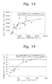
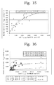
- Figs. 12 to 15 show the results of the amounts of nitrogen that are loaded per bacterial cell per day: L(fg ⁇ copy -1 ⁇ day -1 ) and the maximum reaction rates: V(fg ⁇ copy -1 ⁇ h -1 ) for ammonia-oxidizing bacteria, nitrite-oxidizing bacteria, nitrate-reducing bacteria and nitrite-reducing bacteria, respectively.
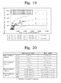
- Fig. 16 also shows that the function that relates V AOB and L AOB is set such that the maximum reaction rate: V AOB (fg ⁇ copy -1 ⁇ h -1 ) satisfies the relation: ⁇ 4.0 ⁇ 10 3 ⁇ L AOB /(1.0 ⁇ 10 4 +L AOB )-2.5 ⁇ 10 3 ⁇ V AOB ⁇ 4.0 ⁇ 10 3 ⁇ L AOB /(1.0 ⁇ 10 4 +L AOB )+2.5 ⁇ 10 3 ⁇ in the case where the amount of ammonia nitrogen: L AOB (fg ⁇ copy -1 ⁇ day -1 ) that is loaded per ammonia-oxidizing bacterial cell per day satisfies the relation of 1.0 ⁇ 10 2 ⁇ L AOB ⁇ 3.5 ⁇ 10 4 , thereby being capable of improving the prediction accuracy of the simulation. It is also shown that the function can be applied to the entire biological treatment of water to be treated in which nitrogen components are contained therein as the substance to be treated, including sewage as well.
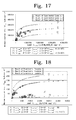
- Fig. 17 also shows that the function that relates V NOB and L NOB is set such that the maximum reaction rate: V NOB (fg ⁇ copy -1 ⁇ h -1 ) satisfies the relation: ⁇ 2.5 ⁇ 10 5 ⁇ L NOB /(4.0 ⁇ 10 5 +L NOB )-1.0 ⁇ 10 5 ⁇ V NOB ⁇ 2.5 ⁇ 10 5 ⁇ L NOB /(4.0 ⁇ 10 5 +L NOB )+1.0 ⁇ 10 5 ⁇ in the case where the amount of nitrite nitrogen: L NOB (fg ⁇ copy -1 ⁇ day -1 ) that is loaded per nitrite-oxidizing bacterial cell per day can satisfy the relation of 1.0 ⁇ 10 3 ⁇ L NOB ⁇ 1.2 ⁇ 10 6 , thereby improving the prediction accuracy of the simulation. It is also shown that the function can be applied to the entire biological treatment of water to be treated in which nitrogen components are contained therein as the substance to be treated, including sewage as well.
- Fig. 18 also shows that the function that relates V NARB and L NARB is set such that the maximum reaction rate: V NARB (fg ⁇ copy -1 ⁇ h -1 ) satisfies the relation: ⁇ 2.2 ⁇ 10 2 ⁇ L NARB /(7.0 ⁇ 10 2 +L NARB )-1.7 ⁇ 10 2 ⁇ V NARB ⁇ 2.2 ⁇ 10 2 ⁇ L NARB /(7.0 ⁇ 10 2 +L NARB )+70 ⁇ in the case where the amount of nitrite nitrogen: L NARB (fg ⁇ copy -1 ⁇ day -1 ) that is loaded per nitrate-reducing bacterial cell per day meets the relation of 5.0 ⁇ L NARB ⁇ 2,500, thereby being capable of improving the prediction accuracy of the simulation. It is also shown that the function can be applied to the entire biological treatment of water to be treated in which nitrogen components are contained therein as the substance to be treated, including sewage as well.
- the function that relates V NIRB and L NIRB is set such that the maximum reaction rate: V NIRB (fg ⁇ copy -1 ⁇ h -1 ) satisfies the relation: ⁇ 7.0 ⁇ 10 2 ⁇ L NIRB /(2.5 ⁇ 10 3 +L NIRB )-2.5 ⁇ 10 2 ⁇ V NIRB ⁇ 7.0 ⁇ 10 2 ⁇ L NIRB /(2.5 ⁇ 10 3 +L NIRB )+2.5 ⁇ 10 2 ⁇ in the case where the amount of nitrite nitrogen: L NIRB (fg ⁇ copy -1 ⁇ day -1 ) that is loaded per nitrite-reducing bacterial cell per day meets the relation of 5.0 ⁇ L NIRB ⁇ 3.5 ⁇ 10 3 , thereby being capable of improving the prediction accuracy of the simulation. It is also shown that the function can be applied to the entire biological treatment of water to be treated in which nitrogen components are contained therein as the substance to be treated, including sewage as well.
- the maximum reaction rate of ammonia oxidation is defined by a function expressed by equation (41): Eq . 54
- V AOB 4.0 ⁇ 10 3 ⁇ L AOB / 1.0 ⁇ 10 4 + L AOB
- V NOB Maximum reaction rate (fg ⁇ copy -1 ⁇ h -1 )
- L NOB Amount of nitrite nitrogen that is loaded per nitrite-oxidizing bacterial cell per day (fg NH 4 -N ⁇ copy -1 ⁇ day -1 )
- the maximum reaction rate of nitrite oxidation is defined by a function expressed by equation (42): Eq .
- V NOB 2.5 ⁇ 10 5 ⁇ L NOB / 4.0 ⁇ 10 5 + L NOB
- V AOB Maximum reaction rate (fg ⁇ copy -1 ⁇ h -1 )
- L AOB Amount of ammonia nitrogen that is loaded per ammonia-oxidizing bacterial cell per day (fg NO 2 -N ⁇ copy -1 ⁇ day -1 ), which are incorporated into a simulation apparatus, and where a denitrification process is further included in the biological treatment process, in addition to functions expressed by equations (41) and (42) above, the maximum reaction rate of nitrate reduction is defined by a function expressed by equation (43): Eq .
- V NARB 2.2 ⁇ 10 2 ⁇ L NARB / 7.0 ⁇ 10 2 + L NARB
- V NARB Maximum reaction rate (fg ⁇ copy -1 ⁇ h -1 )
- L NARB Amount of nitrate nitrogen that is loaded per nitrate-reducing bacterial cell per day (fg NO 3 -N ⁇ copy -1 ⁇ day -1 )
- the maximum reaction rate of nitrite reduction is defined by a function expressed by equation (44): Eq .
- V NIRB 7.0 ⁇ 10 2 ⁇ L NIRB / 2.5 ⁇ 10 3 + L NIRB
- V NIRB Maximum reaction rate (fg ⁇ copy -1 ⁇ h -1 )
- L NIRB Amount of nitrite nitrogen that is loaded per nitrite-reducing bacterial cell per day (fg NO 2 -N ⁇ copy -1 ⁇ day -1 ), which are incorporated into the simulation apparatus, thereby being capable of executing a simulation with high precision.
- This matrix differs from the conventional model in which the maximum reaction rate is constant as indicated in Comparative Table in Fig. 20 .
- the quality of treated water immediately after the nitrogen load was increased by 2.5 times the standard load and the quality of treated water after 48 hours that is considered to be sufficiently affected by the history of the amount of treatment after an increase in load were simulated and compared with actual measurement data.
- the results are illustrated in Figs. 21 (immediately after load increase) and 22 (48 hours after load increase).
- the plots in the drawings indicate the analysis values, and the solid lines and broken lines illustrate the calculated results obtained by the simulation (novel model) into which the relational expression of the maximum reaction rate that is varied depending on the amount of nitrogen that is loaded per bacterial cell per day and the results obtained by ASM3 of conventional calculation, respectively.
- the consumption of ammonia required about 120 minutes in the nitrification process after load increase and the consumption of nitric acid also required about 120 minutes in the denitrification process; however, the ammonia was consumed in about 80 minutes and the nitric acid in about 60 minutes 48 hours after load increase, whereby the improvement in treatment rate was confirmed.
- the generation of the nitrous acid was hardly identified including nitrification and denitrification.
- the calculation results by the simulation of a novel model was able to well reproduce the calculation results immediately after load increase and 48 hours after load increase and also the prediction accuracy of water quality achieved the analysis value ⁇ 20% that is the target value.
- the use of the "amount of a substance to be treated that was treated per bacterial cell per day" as a factor has the advantage of readily obtaining a simulation result with high precision.
- the load per bacterial cell per day is not greatly different from the amount of treatment as illustrated in comparison of Figs. 8 and 16 to 19 with Figs. 23 to 26 , the use of the "amount of a substance to be treated that was treated per bacterial cell per day" as a factor is advantageous from the viewpoint of improving the calculation speed.
- the maximum reaction rate was measured by the same measurement of the maximum reaction rate as in Experimental Example 1 except that a chloride ion concentration was added to the solutions A, B, C and D prepared in Experimental Example 1 such that each of the solutions had concentrations of 2,000 mg/L and 4,000 mg/L. Then, provided that the values of the maximum rates of reaction without the influence of chloride ions were expressed by V AOB0 , V NOB0 , V NARB0 , and V NIRB0 and were regarded as 100, the values of the maximum rates of reaction (V AOB , V NOB , V NARB0 , and V NIRB ) in the case of addition of chloride ions of 2,000 and 4,000 mg/L were evaluated. The results are shown in Figs. 27 to 30 , respectively.
- D CL represents a chloride ion concentration (mg/L)
- V AOB f AOB (L AOB ) ⁇ k AOB (D CL ) is set between the maximum reaction rate: V AOB and the amount of ammoni
- D CL represents a chloride ion concentration (mg/L)
- V NOB f NOB (L NOB ) ⁇ k NOB (D CL )
- a simulation method of being capable of reducing the labor of calibration while suppressing a decrease in prediction accuracy and the like can be executed.
Landscapes
- Life Sciences & Earth Sciences (AREA)
- Microbiology (AREA)
- Chemical & Material Sciences (AREA)
- Engineering & Computer Science (AREA)
- Biodiversity & Conservation Biology (AREA)
- Hydrology & Water Resources (AREA)
- Environmental & Geological Engineering (AREA)
- Water Supply & Treatment (AREA)
- Organic Chemistry (AREA)
- Health & Medical Sciences (AREA)
- Food Science & Technology (AREA)
- Medicinal Chemistry (AREA)
- Physics & Mathematics (AREA)
- Analytical Chemistry (AREA)
- Biochemistry (AREA)
- General Health & Medical Sciences (AREA)
- General Physics & Mathematics (AREA)
- Immunology (AREA)
- Pathology (AREA)
- Molecular Biology (AREA)
- Purification Treatments By Anaerobic Or Anaerobic And Aerobic Bacteria Or Animals (AREA)
- Management, Administration, Business Operations System, And Electronic Commerce (AREA)
Applications Claiming Priority (4)
| Application Number | Priority Date | Filing Date | Title |
|---|---|---|---|
| JP2007161550 | 2007-06-19 | ||
| JP2007287694A JP5255818B2 (ja) | 2007-11-05 | 2007-11-05 | シミュレーション方法 |
| JP2007287698 | 2007-11-05 | ||
| PCT/JP2008/061264 WO2008156151A1 (fr) | 2007-06-19 | 2008-06-19 | Procédé de simulation, appareil de simulation, procédé de traitement biologique et appareil de traitement biologique |
Publications (2)
| Publication Number | Publication Date |
|---|---|
| EP2181966A1 true EP2181966A1 (fr) | 2010-05-05 |
| EP2181966A4 EP2181966A4 (fr) | 2014-02-19 |
Family
ID=40156309
Family Applications (1)
| Application Number | Title | Priority Date | Filing Date |
|---|---|---|---|
| EP08765759.9A Withdrawn EP2181966A4 (fr) | 2007-06-19 | 2008-06-19 | Procédé de simulation, appareil de simulation, procédé de traitement biologique et appareil de traitement biologique |
Country Status (3)
| Country | Link |
|---|---|
| US (1) | US20110015913A1 (fr) |
| EP (1) | EP2181966A4 (fr) |
| WO (1) | WO2008156151A1 (fr) |
Cited By (2)
| Publication number | Priority date | Publication date | Assignee | Title |
|---|---|---|---|---|
| CN105548296A (zh) * | 2015-12-07 | 2016-05-04 | 清华大学 | 一种活性污泥氨氮利用速率在线检测装置及检测方法 |
| US11225680B2 (en) | 2015-04-03 | 2022-01-18 | Sumitomo Chemical Company, Limited | Prediction-rule generating system, prediction system, prediction-rule generating method, and prediction method |
Families Citing this family (7)
| Publication number | Priority date | Publication date | Assignee | Title |
|---|---|---|---|---|
| JP4672816B1 (ja) * | 2009-08-28 | 2011-04-20 | 関西熱化学株式会社 | 生物処理方法 |
| JP5733785B2 (ja) * | 2009-10-20 | 2015-06-10 | メタウォーター株式会社 | 排水処理方法及び排水処理装置 |
| JP7402867B2 (ja) * | 2018-10-12 | 2023-12-21 | クオリティー エグゼクティブ パートナーズ インコーポレイテッド | 仮想現実シミュレーション及び方法 |
| US10584045B1 (en) * | 2019-03-29 | 2020-03-10 | Richard E. Speece | Conversion of secondary clarifier into an oxic bioreactor by superoxygenation |
| US12313618B2 (en) * | 2021-02-12 | 2025-05-27 | Hach Company | Predictive model for water quality deterioration |
| CN116429507B (zh) * | 2023-03-10 | 2025-08-19 | 长春黄金研究院有限公司 | 一种大型生物氧化槽深度取样分析装置及方法 |
| CN119830755B (zh) * | 2024-12-31 | 2025-08-12 | 北京思路智园科技有限公司 | 一种动态管式连续硝化工艺仿真装置及仿真系统 |
Family Cites Families (18)
| Publication number | Priority date | Publication date | Assignee | Title |
|---|---|---|---|---|
| US2394042A (en) * | 1941-07-30 | 1946-02-05 | Gen Electric | Triazine derivatives |
| CH588213A5 (fr) * | 1974-07-25 | 1977-05-31 | Ciba Geigy Ag | |
| PH23300A (en) * | 1985-12-02 | 1989-06-30 | Ciba Geigy Ag | (di) alkoxy carbonylamino-s-triazine derivatives and the use thereof against pests which are parasite of domestic animals and cultivated plants |
| JPH07106357B2 (ja) | 1987-02-27 | 1995-11-15 | 株式会社明電舎 | 水処理装置 |
| US5084541A (en) * | 1988-12-19 | 1992-01-28 | American Cyanamid Company | Triazine crosslinking agents and curable compositions |
| TW328955B (en) * | 1993-05-14 | 1998-04-01 | Cytec Tech Corp | Process for preparing bis- or tris-carbamate functional 1,3,5-triazines, substantially halogen contamination free crosslinker compositions and new bis-or tris-carbamate functional 1,3,5-triazines |
| JPH08323393A (ja) | 1995-05-31 | 1996-12-10 | Meidensha Corp | 循環式硝化脱窒法の水質シミュレーション装置 |
| JPH0947785A (ja) | 1995-08-10 | 1997-02-18 | Hitachi Plant Eng & Constr Co Ltd | 硝化反応シミュレーション方法及び装置 |
| BR9911246A (pt) * | 1998-06-16 | 2001-03-13 | Cytec Tech Corp | Processo para a preparação de um derivado de 1,3,5-triazina carbamato |
| JP2000107796A (ja) | 1998-09-30 | 2000-04-18 | Toshiba Corp | 下水処理プロセスシミュレータシステム |
| JP2001334253A (ja) * | 2000-05-30 | 2001-12-04 | Toshiba Corp | 水質シミュレータ |
| ATE483695T1 (de) * | 2001-10-23 | 2010-10-15 | Basf Se | Verfahren zur herstellung von alkoxycarbonylamino-triazinen |
| SE521571C2 (sv) * | 2002-02-07 | 2003-11-11 | Greenfish Ab | Integrerat slutet recirkulerande system för rening av spillvatten i vattenbruk. |
| DE10259672A1 (de) * | 2002-12-18 | 2004-07-01 | Basf Ag | Verfahren zur Herstellung von Alkoxycarbonylamino-triazinen |
| WO2005030735A1 (fr) * | 2003-09-25 | 2005-04-07 | Ranbaxy Laboratories Limited | Derives de triazines comme inhibiteurs de l'adhesion cellulaire |
| DE102004018543A1 (de) * | 2004-04-14 | 2005-11-10 | Basf Ag | Carbamatgruppenhaltige Triazinderivate |
| DE102004018546A1 (de) * | 2004-04-14 | 2005-11-03 | Basf Ag | Strahlungshärtbare 1,3,5-Triazincarbamate und -harnstoffe |
| DE102004018544A1 (de) * | 2004-04-14 | 2005-11-03 | Basf Ag | Verfahren zur Herstellung von 1,3,5-Triazincarbamaten und -harnstoffen |
-
2008
- 2008-06-19 EP EP08765759.9A patent/EP2181966A4/fr not_active Withdrawn
- 2008-06-19 WO PCT/JP2008/061264 patent/WO2008156151A1/fr not_active Ceased
- 2008-06-19 US US12/665,390 patent/US20110015913A1/en not_active Abandoned
Cited By (3)
| Publication number | Priority date | Publication date | Assignee | Title |
|---|---|---|---|---|
| US11225680B2 (en) | 2015-04-03 | 2022-01-18 | Sumitomo Chemical Company, Limited | Prediction-rule generating system, prediction system, prediction-rule generating method, and prediction method |
| CN105548296A (zh) * | 2015-12-07 | 2016-05-04 | 清华大学 | 一种活性污泥氨氮利用速率在线检测装置及检测方法 |
| CN105548296B (zh) * | 2015-12-07 | 2018-08-28 | 清华大学 | 一种活性污泥氨氮利用速率在线检测装置及检测方法 |
Also Published As
| Publication number | Publication date |
|---|---|
| EP2181966A4 (fr) | 2014-02-19 |
| WO2008156151A1 (fr) | 2008-12-24 |
| US20110015913A1 (en) | 2011-01-20 |
Similar Documents
| Publication | Publication Date | Title |
|---|---|---|
| JP5049748B2 (ja) | 生物学的水処理のシミュレーション方法およびシミュレーション装置 | |
| Li et al. | Adaptation of nitrifying community in activated sludge to free ammonia inhibition and inactivation | |
| US20110015913A1 (en) | Simulation Method, Simulation Apparatus, Biological Treatment Method, and Biological Treatment Apparatus | |
| Qin et al. | The dissipation and risk alleviation mechanism of PAHs and nitrogen in constructed wetlands: The role of submerged macrophytes and their biofilms-leaves | |
| Miao et al. | Enhancing ammonium oxidizing bacteria activity was key to single-stage partial nitrification-anammox system treating low-strength sewage under intermittent aeration condition | |
| Wen et al. | Nitrification kinetics and microbial communities of activated sludge as a full-scale membrane bioreactor plant transitioned to low dissolved oxygen operation | |
| Sui et al. | Response of nitrite accumulation and microbial community to free ammonia and dissolved oxygen treatment of high ammonium wastewater | |
| Świątczak et al. | Performance and microbial characteristics of biomass in a full-scale aerobic granular sludge wastewater treatment plant | |
| Stasinakis et al. | Effect of chromium (VI) on bacterial kinetics of heterotrophic biomass of activated sludge | |
| Li et al. | Long-term partial nitrification in an intermittently aerated sequencing batch reactor (SBR) treating ammonium-rich wastewater under controlled oxygen-limited conditions | |
| Wu et al. | Effect of short term external perturbations on bacterial ecology and activities in a partial nitritation and anammox reactor | |
| Manefield et al. | Functional and compositional comparison of two activated sludge communities remediating coking effluent | |
| Li et al. | Microbial diversity and community distribution in different functional zones of continuous aerobic–anaerobic coupled process for sludge in situ reduction | |
| Kim et al. | Comparison of conventional and integrated fixed‐film activated sludge systems: Attached‐and suspended‐growth functions and quantitative polymerase chain reaction measurements | |
| Figuerola et al. | Diversity of nitrifying bacteria in a full-scale petroleum refinery wastewater treatment plant experiencing unstable nitrification | |
| Liu et al. | Identification of optimal parameters for treatment of high-strength ammonium leachate by mixed communities of heterotrophic nitrifying/aerobic denitrifying bacteria | |
| Lan et al. | NO and N2O accumulation during nitrite-based sulfide-oxidizing autotrophic denitrification | |
| Jia et al. | Sediment diffusion is feasible to simultaneously reduce nitrate discharge from recirculating aquaculture system and ammonium release from sediments in receiving intensive aquaculture pond | |
| González-Cortés et al. | Characterization of bacterial and Archaeal communities by DGGE and next generation sequencing (NGS) of nitrification bioreactors using two different intermediate landfill leachates as ammonium substrate | |
| Ding et al. | Enrichment of anammox biomass from different seeding sludge: process strategy and microbial diversity | |
| Britschgi et al. | The critical role of flocs in nitrification in full-scale aerobic granular sludge-based WWTP | |
| Fan et al. | Microecology of aerobic denitrification system construction driven by cyclic stress of sulfamethoxazole | |
| Huang et al. | Nanoarchitectured structure and population dynamics of anaerobic ammonium oxidizing (anammox) bacteria in a wastewater treatment plant | |
| Li et al. | Variation, distribution, and diversity of canonical ammonia-oxidizing microorganisms and complete-nitrifying bacteria in highly contaminated ecological restoration regions in the Siding mine area | |
| Zhang et al. | The significant contribution of comammox bacteria to nitrification in a constructed wetland revealed by DNA-based stable isotope probing |
Legal Events
| Date | Code | Title | Description |
|---|---|---|---|
| PUAI | Public reference made under article 153(3) epc to a published international application that has entered the european phase |
Free format text: ORIGINAL CODE: 0009012 |
|
| 17P | Request for examination filed |
Effective date: 20100108 |
|
| AK | Designated contracting states |
Kind code of ref document: A1 Designated state(s): AT BE BG CH CY CZ DE DK EE ES FI FR GB GR HR HU IE IS IT LI LT LU LV MC MT NL NO PL PT RO SE SI SK TR |
|
| AX | Request for extension of the european patent |
Extension state: AL BA MK RS |
|
| RIN1 | Information on inventor provided before grant (corrected) |
Inventor name: AKASHI, AKIRA Inventor name: TSUJI, KOJI Inventor name: FUJITA, MASAFUMI Inventor name: TAKEZAKI, JUN Inventor name: MINAKAWA, MIE Inventor name: TAKEDA, NAOHIRO Inventor name: YAMASHITA, TETSUO |
|
| DAX | Request for extension of the european patent (deleted) | ||
| RIC1 | Information provided on ipc code assigned before grant |
Ipc: G01N 33/18 20060101ALI20131220BHEP Ipc: C02F 3/34 20060101AFI20131220BHEP Ipc: C02F 3/12 20060101ALI20131220BHEP |
|
| A4 | Supplementary search report drawn up and despatched |
Effective date: 20140116 |
|
| STAA | Information on the status of an ep patent application or granted ep patent |
Free format text: STATUS: THE APPLICATION IS DEEMED TO BE WITHDRAWN |
|
| 18D | Application deemed to be withdrawn |
Effective date: 20140815 |