EP2181977A2 - Appareil pour coller de films et procédé de collage de films - Google Patents
Appareil pour coller de films et procédé de collage de films Download PDFInfo
- Publication number
- EP2181977A2 EP2181977A2 EP09252518A EP09252518A EP2181977A2 EP 2181977 A2 EP2181977 A2 EP 2181977A2 EP 09252518 A EP09252518 A EP 09252518A EP 09252518 A EP09252518 A EP 09252518A EP 2181977 A2 EP2181977 A2 EP 2181977A2
- Authority
- EP
- European Patent Office
- Prior art keywords
- film
- honeycomb structure
- face
- sticking
- pressing
- Prior art date
- Legal status (The legal status is an assumption and is not a legal conclusion. Google has not performed a legal analysis and makes no representation as to the accuracy of the status listed.)
- Granted
Links
Images


Classifications
-
- B—PERFORMING OPERATIONS; TRANSPORTING
- B28—WORKING CEMENT, CLAY, OR STONE
- B28B—SHAPING CLAY OR OTHER CERAMIC COMPOSITIONS; SHAPING SLAG; SHAPING MIXTURES CONTAINING CEMENTITIOUS MATERIAL, e.g. PLASTER
- B28B11/00—Apparatus or processes for treating or working the shaped or preshaped articles
- B28B11/003—Apparatus or processes for treating or working the shaped or preshaped articles the shaping of preshaped articles, e.g. by bending
- B28B11/006—Making hollow articles or partly closed articles
- B28B11/007—Using a mask for plugging
-
- B—PERFORMING OPERATIONS; TRANSPORTING
- B28—WORKING CEMENT, CLAY, OR STONE
- B28B—SHAPING CLAY OR OTHER CERAMIC COMPOSITIONS; SHAPING SLAG; SHAPING MIXTURES CONTAINING CEMENTITIOUS MATERIAL, e.g. PLASTER
- B28B11/00—Apparatus or processes for treating or working the shaped or preshaped articles
- B28B11/003—Apparatus or processes for treating or working the shaped or preshaped articles the shaping of preshaped articles, e.g. by bending
- B28B11/006—Making hollow articles or partly closed articles
-
- Y—GENERAL TAGGING OF NEW TECHNOLOGICAL DEVELOPMENTS; GENERAL TAGGING OF CROSS-SECTIONAL TECHNOLOGIES SPANNING OVER SEVERAL SECTIONS OF THE IPC; TECHNICAL SUBJECTS COVERED BY FORMER USPC CROSS-REFERENCE ART COLLECTIONS [XRACs] AND DIGESTS
- Y10—TECHNICAL SUBJECTS COVERED BY FORMER USPC
- Y10T—TECHNICAL SUBJECTS COVERED BY FORMER US CLASSIFICATION
- Y10T156/00—Adhesive bonding and miscellaneous chemical manufacture
- Y10T156/10—Methods of surface bonding and/or assembly therefor
- Y10T156/1002—Methods of surface bonding and/or assembly therefor with permanent bending or reshaping or surface deformation of self sustaining lamina
- Y10T156/1028—Methods of surface bonding and/or assembly therefor with permanent bending or reshaping or surface deformation of self sustaining lamina by bending, drawing or stretch forming sheet to assume shape of configured lamina while in contact therewith
- Y10T156/1033—Flexible sheet to cylinder lamina
Definitions
- the present invention relates to a film sticking apparatus and a film sticking method, and specifically to a film sticking apparatus and a film sticking method capable of automatically sticking a film to a honeycomb structure.
- Exhaust gas discharged from internal combustion engine such as diesel engine contains large amounts of particulates (particulate matter) containing carbon as the main component acting as a cause of environmental pollution. Accordingly the exhaust system of diesel engine and the like is ordinarily provided with a filter to collect the particulates.
- the plugged honeycomb structure 150 includes: a honeycomb structure 50 having porous partition walls 52 that partition and form a plurality of cells 51; and plugging sections 53 being arranged to plug one end of the two open end sections of each cell 51, and the plugging sections 53 are arranged in a complementary checkered pattern on each of one end face side and the other end face side of the honeycomb structure 50.
- the method for manufacturing the plugged honeycomb structure there is a known method in which after a film having an adhesive face (hereinafter the film is also referred to as a "mask") is stuck to one end face of a non-fired honeycomb structure, and a hole is opened at a portion of the mask covering the cell in which the plugging section is to be arranged, using laser machining utilizing an image processing, or the like, an end portion to which the mask is stuck is immersed in a slurry for plugging, the slurry for plugging is filled and dried in the end portion of the cell, the mask stuck to the end face is peeled, and then the honeycomb structure is fired.
- a film having an adhesive face hereinafter the film is also referred to as a "mask”
- Patent Document 1 includes the step of sticking a film to one end face and to a part of side face of a honeycomb structure by hand.
- the sticking job may generate wrinkle or slack of the stuck film unless the job is done by a skilled worker. Once that wrinkle and slack occurred, good formation of the plugging section becomes difficult in some cases. Furthermore, even a skilled worker takes a time in film-sticking job.
- the present invention has been developed to solve the above-described problems in the related art, and an issue of the present invention is to provide a film sticking apparatus and a film sticking method capable of automatically sticking a film to a honeycomb structure.
- the present invention provides a film sticking apparatus and a film sticking method to be described below.
- a film sticking apparatus comprising: a gripping member gripping a film having an adhesive face to hold the film in a planar state; a pressing member pressing the adhesive face of the film being held in a planar state against one end face of a cylindrical honeycomb structure having a plurality of cells formed that communicate between two end faces thereof, and thus sticking the film to the one end face; and a folding member having an opening portion formed that allows an end of the honeycomb structure on the side to which the film is stuck to be inserted, a hardness of the folding member having 10 degrees at the lower limit and 60 degrees at the upper limit, wherein the folding member folds a protruding portion of the film protruding from the one end face of the honeycomb structure by inserting the honeycomb structure into the opening portion, toward a side face of the honeycomb structure, and simultaneously presses at least a part of the folded protruding portion against a part of the side face of the honeycomb structure to stick the film to the side face.
- a film sticking method for sticking a film to a honeycomb structure using the film sticking apparatus comprising the steps of: gripping a film to hold the film in a planar state with the gripping member; positioning the honeycomb structure so that the adhesive face of the film being held in a planar state may face the one end face of the honeycomb structure; sticking the film to the one end face by pressing the adhesive face of the film against the one end face of the honeycomb structure with the pressing member; and folding a protruding portion of the film toward a side face of the honeycomb structure by inserting the honeycomb structure into the opening portion of the folding member, and simultaneously pressing at least a part of the folded protruding portion against a part of the side face of the honeycomb structure.
- the film sticking apparatus provides an effect of capable of automatically sticking a film to a honeycomb structure.
- the film sticking method according to the present invention provides an effect of capable of automatically sticking a film to a honeycomb structure.
- Fig. 1 is a schematic perspective view of an embodiment of a film sticking apparatus according to the present invention.
- Fig. 2 illustrates a side view of the film sticking apparatus given in Fig. 1 .
- Fig. 3 illustrates a side view of the film sticking apparatus given in Fig. 1 , in an operating state.
- Fig. 4 illustrates a side view of the film sticking apparatus given in Fig. 1 , in an operating state.
- Fig. 5 illustrates a side view of the film sticking apparatus given in Fig. 1 , in an operating state.
- Fig. 6 illustrates a side view of the film sticking apparatus given in Fig. 1 , in an operating state.
- Fig. 7 illustrates a side view of the film sticking apparatus given in Fig. 1 , in an operating state.
- Fig. 1 is a schematic perspective view of an embodiment of a film sticking apparatus according to the present invention.
- Fig. 2 illustrates a side view of the film sticking apparatus given in Fig. 1 .
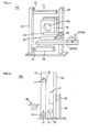
- FIG. 8 is a perspective view of a honeycomb structure in a film-stuck state.
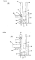
- Fig. 9 is an explanatory diagram illustrating the positional relation between the honeycomb structure and a folding member.
- Fig. 10 is a cross sectional view of the honeycomb structure provided with the plugging sections.
- Fig. 1 is a schematic perspective view of an embodiment of the film sticking apparatus according to the present invention.
- a film sticking apparatus 100 of the embodiment includes: a gripping member 11 gripping a film having an adhesive face to hold the film in a planar state; a pressing member 21 pressing the adhesive face of the film being held in a planar state against one end face of a cylindrical honeycomb structure having a plurality of cells formed that communicate between two end faces thereof, and thus sticking the film to the one end face; a folding member 31 having an opening portion 31a formed that allows an end of the honeycomb structure on the side to which the film is stuck to be inserted, a hardness of the folding member having 10 degrees at the lower limit and 60 degrees at the upper limit; and a transfer bed 40 for transferring the honeycomb structure to a specified position.
- the folding member 31 folds a protruding portion of the film protruding from the one end face of the honeycomb structure by inserting the honeycomb structure into the opening portion 31a, toward a side face of the honeycomb structure, and simultaneously presses at least a part of the folded protruding portion against a part of the side face of the honeycomb structure to stick the film to the side face.
- the film sticking apparatus 100 can automatically stick the film to the honeycomb structure.
- Fig. 2 illustrates a side view of the film sticking apparatus 100 given in Fig. 1 .
- the film sticking apparatus 100 is configured by arranging the members sequentially beginning from the transfer bed 40 side, the gripping member 11, the pressing member 21, and the folding member 31.
- the gripping member attached to the film sticking apparatus of the embodiment grips a film having an adhesive face to hold the film in a planar state. Since that type of gripping member holds the film in a planar state, the film can be stuck to an end face of the honeycomb structure without generating wrinkle and slack.
- the gripping member 11 of the film sticking apparatus 100 illustrated in Fig. 1 has a pair of claws, each having a semi-cylindrical shape, thus giving approximately a cylindrical shape as a whole.
- the film sticking apparatus 100 shown in Fig. 1 has a driving mechanism 12 opening/closing the pair of claws of the gripping member 11, a first support pillar 13 equipped with the driving mechanism 12 which can move up and down, a support rod 15 being fixed at a lower part of the first support pillar 13 and positioned so that the longitudinal central axis thereof may become in parallel with the longitudinal central axis of the gripping member 11, and a cut-out member (not shown) for cutting the film.
- the support rod 15 is provided with a cylindrical film roll 16.
- the film roll 16 is formed by taking up a film 16a having an adhesive face.
- the gripping member is not specifically limited in the configuration as far as the member can grip and draw one end of the film, and can use the one made of resin, metal, and the like.
- the pair of claws of the gripping member may be in pipe shape having a cross sectional shape of rectangular, elliptical, polygonal, and the like.
- the gripping member is not limited to the one having a pair of claws, and the one having bar-shape can be used.
- polyester resin polypropylene resin
- vinyl chloride resin are preferred. Those resins provide good masking on the end face and on the side face of the honeycomb structure.
- Preferred material, (adhesive), for forming the adhesive face includes an acrylic-base adhesive, a rubber-base adhesive, and a silicone-base adhesive.
- the lower limit is preferably 5 ⁇ m, and more preferably 12 ⁇ m.
- the upper limit thereof is preferably 100 ⁇ m, and more preferably 50 ⁇ m. If the thickness is smaller than 5 ⁇ m, there is a possibility of difficulty in sticking a film to the honeycomb structure without generating wrinkle and slack. On the other hand, if the thickness exceeds 100 ⁇ m, the film supporting strength increases, resulting in difficulty in sticking a film to the honeycomb structure in some cases.
- the pressing member of the film sticking apparatus in the embodiment is the one to press the adhesive face of the film held in a planar state against one end face of the columnar honeycomb structure having a plurality of cells formed that communicate between two end faces thereof, from the non-adhesive face side, thus sticking the film to the one end face thereof. That type of pressing member enables the film to stick to the end face of the honeycomb structure without generating wrinkle and slack.
- the pressing member has no specific limitation in the shape and the like if only the pressing member can press the film against one end face of the honeycomb structure, and can stick the film to the one end face thereof.
- the pressing member may have larger area or smaller area than the area of the end face of the honeycomb structure.
- the method for pressing the film against the end face has no specific limitation.
- a pressing member having larger area than the area of the end face of the honeycomb structure can be used to stick the film in one shot.
- sticking may proceed beginning from an edge of one end face gradually.
- the pressing member used in the method of sticking the film beginning from an edge of one end face gradually can adopt, for example, the one in plate shape, cylindrical shape, elliptical prism shape, quadrangular prism shape, and polygonal prism shape.
- preferable one is cylindrical shape rotatably supported around the longitudinal central axis, being positioned so that the longitudinal central axis thereof may become in parallel with the film held in a planar state. That type of pressing member enables the film to be stuck to one end face of the honeycomb structure in good condition without generating wrinkle and slack.
- the member may not be a rotatable one.
- the rotatable member provides better sticking of the film to an end face of the honeycomb structure because the friction generated between the pressing member and the film decreases on pressing the film against the end face.
- the pressing member 21 of the film sticking apparatus 100 illustrated in Fig. 1 is in cylindrical shape rotatably supported around the longitudinal central axis, and being positioned so that the longitudinal central axis thereof may become in parallel with the film held in a planar state.
- the film sticking apparatus 100 illustrated in Fig. 1 has a lift mechanism 22 supporting the pressing member 21, and a second support pillar 23 equipped with the lift mechanism 22 which can move up and down.
- the lift mechanism 22 has a projection arm 22a.
- the projection arm 22a allows the lift mechanism 22 to protrude in the direction orthogonal to the second support pillar 23.
- Fig. 5 illustrates the state that the lift mechanism 22 protrudes, by the action of the projection arm 22a, in the direction orthogonal to the second support pillar 23.
- the material of the pressing member is not specifically limited, urethane resin, silicone resin, and polyethylene resin are preferred. Those kinds of materials enable the film to be stuck to one end face of the honeycomb structure in better condition without generating wrinkle and slack.
- the lower limit is preferably 30 degrees, more preferably 40 degrees, and most preferably 45 degrees.
- the upper limit thereof is preferably 90 degrees, more preferably 85 degrees, and most preferably 80 degrees. If the hardness is smaller than 30 degrees, there may occur difficulty in sticking film to the end face without generating wrinkle and slack. If the hardness exceeds 90 degrees, the film may be broken.
- the term "hardness” referred to herein is the value determined by an ASKER rubber durometer having a needle, in circular truncated cone shape with 2.5 mm in height, directly impinging vertically on a flat face of the pressing member or the folding member.
- the size can arbitrarily be selected.
- the lower limit of the diameter is preferably 10 mm, more preferably 15 mm, and most preferably 20 mm.
- the upper limit thereof is preferably 50 mm, more preferably 40 mm, and most preferably 35 mm.
- the lower limit is preferably 50 mm, more preferably 100 mm, and most preferably 150 mm.
- the upper limit thereof is preferably 1000 mm, more preferably 900 mm, and most preferably 850 mm.
- the honeycomb structure has porous partition walls that partition and form a plurality of cells.
- That type of honeycomb structure can be manufactured by kneading a ceramic powder such as silicon carbide, cordierite, cordierite-forming raw material, and aluminum titanate-forming raw material, with an organic binder, water, and the like to form a clay-like kneaded puddle, and then the kneaded puddle is formed into a honeycomb shape using an extruder or the like, followed by drying the honeycomb shape.
- cordierite-forming raw material signifies a mixed material of silica (SiO 2 ) by 42% to 56% by mass, alumina (Al 2 O 3 ) by 30% to 45% by mass, and magnesia (MgO) by 12% to 16% by mass, the mixture being fired to form the cordierite.
- the folding member of the film sticking apparatus of the embodiment has an opening portion formed that allows an end portion of the honeycomb structure on the side to which the film is stuck to be inserted, and has the hardness of 10 degrees as the lower limit, and 60 degrees as the upper limit.
- the folding member folds the protruding portion of the film protruded from one end face of the honeycomb structure toward a side face of the honeycomb structure, and simultaneously presses at least a part of the folded protruding portion against a part of the side face of the honeycomb structure to stick the film to the side face.
- the film stuck to the side face of the honeycomb structure has an advantage of not generating wrinkle and slack.
- the honeycomb structure is protected. That is, even when the honeycomb structure is subjected to impact at the side face, the honeycomb structure has an advantage to be not easily broken.
- the step of forming the plugging section to plug the cell there is an advantage that, when immersing the honeycomb structure in the slurry for plugging thereof and introducing the slurry under pressure into the cell, the honeycomb structure can be easily immersed in the slurry and easily accept the introduction of the slurry into the cell under pressure.
- the folding member is preferably made of urethane resin, silicone resin, or polyethylene resin. Among these, the one made of urethane resin is preferred.
- the folding member made of urethane resin has an advantage of obtaining good sticking performance because the surface of the urethane resin is adequately deformed by the honeycomb structure.
- the hardness of the folding member is required to be 10 degrees as the lower limit, preferably 15 degrees, and more preferably 20 degrees.
- the upper limit thereof is necessary to be 60 degrees, preferably 50 degrees, and more preferably 45 degrees. If the hardness thereof is smaller than 10 degrees, the sufficient stickiness of the film to the side face of the honeycomb structure becomes difficult to obtain. If the hardness thereof exceeds 60 degrees, the film is broken when the honeycomb structure is pushed into the opening portion.
- the shape of the folding member can be in a shape of, for example, cylinder, elliptic prism, quadrangular prism, polygonal prism, and cone.
- the lower limit of the thickness in the longitudinal direction is preferably 30 mm, and more preferably 40 mm.
- the upper limit thereof is preferably 150 mm, and more preferably 100 mm.
- the face that can be contacted with the honeycomb structure preferably has the lower limit of 20 mm as the minimum distance between the outer periphery thereof and the open edge of the opening portion, and more preferably 50 mm.
- the upper limit thereof is preferably 200 mm.
- the opening portion may be a space in any shape if only the portion accepts the insertion of the honeycomb structure
- the shape of the open edge preferably has the same shape or a similar shape with the shape of the end face of the honeycomb structure.
- the shape is preferably in circular shape, elliptical shape, oval shape, or quadrangular shape.
- a circular shape of the open edge of the opening portion enables the film to be stuck to a part of the side face in better condition.
- the folding member 31 of the film sticking apparatus 100 illustrated in Fig. 1 has the opening portion 31a formed, which has circular shape of the open edge and allows a honeycomb structure 50 to be inserted thereinto.
- the film sticking apparatus 100 illustrated in Fig. 1 is provided with a fixing plate 32 that fixes the folding member 31 and has a penetration hole formed that has a similar opening diameter with that of the folding member 31, a driving cylinder 35 connected to the fixing plate 32, and a third support pillar 36 supporting the driving cylinder 35.
- the driving cylinder 35 contains a shaft 37 therein. When the shaft 37 is taken out, the fixing plate 32, or the folding member 31, can be pushed outward.
- the opening diameter of the opening portion is preferably in a range of ⁇ 5 mm toward its inside, and a uniform opening diameter is more preferred.
- the film can be stuck to a part of side face in better condition without generating wrinkle and slack.
- the folding member 31 given in Fig. 9 has the opening diameter of the opening portion 31a to be uniform toward its inside.
- the term "toward its inside” referred to herein means "from one open edge toward the other open edge".
- the term "in a range of ⁇ 5 mm toward its inside” referred to herein means that the inside wall forming the opening portion forms a space in conical shape, and that the difference between the opening diameter of one open edge and the opening diameter of the other open edge is ⁇ 5 mm.
- the term "uniform toward its inside” referred to herein means that the inside wall forming the opening portion forms a space in cylindrical shape.
- the opening diameter of the opening portion can be appropriately selected if only the protruding portion of the film can be folded toward a side face of the honeycomb structure, and at least a part of the folded protruding portion of the film can be stuck to a part of the side face of the honeycomb structure.
- the opening diameter of the opening portion has the upper limit of +5 mm, more preferably 0 mm, and most preferably -5 mm to the outer diameter of the end face of the honeycomb structure.
- the lower limit thereof is preferably -30 mm, more preferably -20 mm, and most preferably -15 mm.
- the term "to the outer diameter of the end face of the honeycomb structure" referred to herein means "the distance between the outer peripheral edge of the end face of the honeycomb structure and the open edge of the opening portion, and to the length normal to the tangent of the above-described outer peripheral edge”.
- the above-described opening diameter is not necessarily required to be uniform all over the outer peripheral edge. At, for example, a steeply curved section, the opening diameter can decrease from that at the linear portion to increase the adhesiveness.
- the film sticking apparatus according to the present invention can be used as an apparatus for sticking a film to a honeycomb structure in a shape of cylinder, quadrangular prism, elliptical prism, or the like.
- a honeycomb structure in cylindrical shape is the one having the diameter of about 75 mm to about 450 mm at the end face.
- the opening portion may be a hole penetrating the folding member, or a concave portion that does not penetrate the folding member.
- the penetration hole is, however, preferred.
- the penetration hole makes the folding member easily stick to the side face of the honeycomb structure. That is, the adhesiveness of the film to the side face of the honeycomb structure improves.
- the film sticking apparatus in the embodiment preferably further includes a transfer bed for transferring the honeycomb structure to a specified position.
- a transfer bed for transferring the honeycomb structure to a specified position.
- the film sticking apparatus 100 includes a honeycomb-placing section 41 to place the honeycomb structure 50 thereon, and a transfer bed 40 having a transfer conveyer 42 for moving the honeycomb-placing section 41.
- transfer conveyer examples include bar conveyer, belt conveyer, and walking beam.
- An example of the transfer bed is turntable.
- the film sticking apparatus of the embodiment can be equipped with a cut-out member to cut off the film from a film roll after sticking the film to the honeycomb structure, a chucking member to chuck the film, a neutralization member to remove static electricity from the film, and the like.
- An example of the cut-out member is the one having a cut-out section such as a blade, a driving section to make the cut-out section movable, and a support section for cutting out equipped with the driving section.
- the cut-out member may be, for example, fixed to the first support pillar 13, or may be separately positioned.
- An embodiment of the film sticking method is a method of sticking a film to a honeycomb structure using the film sticking apparatus of the present invention.
- the method includes the steps of: gripping a film to hold the film in a planar state with the gripping member; positioning the honeycomb structure so that the adhesive face of the film being held in a planar state may face the one end face of the honeycomb structure; sticking the film to the one end face by pressing the adhesive face of the film against the one end face of the honeycomb structure with the pressing member; and folding a protruding portion of the film toward a side face of the honeycomb structure by inserting the honeycomb structure into the opening portion of the folding member, and simultaneously pressing at least a part of the folded protruding portion against a part of the side face of the honeycomb structure. With these steps, the film can be automatically stuck to the honeycomb structure.
- the film sticking method of the embodiment firstly performs the step of gripping a film to hold the film in a planar state with the gripping member. This step makes it possible to easily stick the film to one end face, and also to stick the film to the end face without generating wrinkle and slack.
- the gripping member applied to the step can suitably adopt the gripping member similar to the above-described one.
- the film can suitably use the film similar to the above-described one.
- Fig. 3 illustrates a side view of the film sticking apparatus 100 given in Fig. 1 , in an operating state.
- the figure illustrates the state after gripping the film 16a with the gripping member 11, and on drawing-out the film 16a to a specified position. Once the film 16a is drawn out to the specified position, the honeycomb structure 50 is placed on the honeycomb-placing section 41 of the transfer bed 40.
- the film sticking method of the embodiment performs the step of positioning the honeycomb structure so that the adhesive face of the film being held in a planar state may face the one end face of the honeycomb structure.
- a transfer bed for example the transfer bed 40 shown in Fig. 1
- Fig. 4 shows the state that the transfer bed 40 positions the honeycomb structure 50 so that the adhesive face of the film 16a and one end face of the honeycomb structure 50 may face with each other.
- the method performs the step of sticking the film to one end face by pressing the adhesive face of the film against the one end face of the honeycomb structure with the pressing member.
- the film can be stuck to one end face of the honeycomb structure without generating wrinkle and slack.
- the pressing member used in the step suitably adopts the pressing member similar to the above-described one, and the member preferably has cylindrical shape rotatable around the longitudinal central axis, and is preferably positioned so that the longitudinal central axis may become orthogonal to the longitudinal central axis of the honeycomb structure.
- the term "orthogonal" referred to herein is not limited to the configuration where the central axis of the pressing member directly crosses orthogonally the central axis of the honeycomb structure, and includes the concept that, when projecting these central axes, both shadows cross orthogonally with each other.
- Fig. 5 illustrates the state that the rotatable cylindrical pressing member 21 presses the adhesive face of the film 16a against one end face of the honeycomb structure 50 to stick the film 16a to the one end face.
- the pressing member preferably presses the film against an end face of the honeycomb structure while rotating and traveling in parallel with the end face at a speed ranging from 30 to 800 mm/sec, more preferably in a range from 35 to 500 mm/sec, and most preferably from 40 to 100 mm/sec. If the travel speed of the pressing member is smaller than 30 mm/sec, the productivity may deteriorate because the film-sticking operation takes an excessively long time. If the travel speed exceeds 60 mm/sec, sufficient sticking of the film to the end face may fail.
- the pressing member may be an independently rotatable one
- a preferable one is to become rotatable by bringing the pressing member in, for example, cylindrical shape contact with the film, or the one becoming rotatable by the frication force generated between the pressing member and the film.
- the number of pressings of the film against the end face by the pressing member is preferably in a range from 2 to 8, more preferably from 3 to 6, and most preferably from 4 to 5. If the number is less than 2, the film may fail to be satisfactorily stuck to the end face. If the number exceeds 8, the film-sticking operation takes an excessively long time, thus the productivity may deteriorate.
- the term "the number of pressings of the film against the end face by the pressing member" referred to herein mean the number of returns of the pressing member to the original position. That is, in Fig. 5 , one cycle is defined as the movement of the pressing member: traveling upward while pressing the film against the end face, then traveling downward while pressing the film against the end face, thus returning to the original position before starting.
- the pressing strength is not specifically limited as far as the strength does not cause the partition wall of the honeycomb structure to get chipped or not induce break of the film, and as far as the film adhesiveness is assured. It is, however, preferable that the strength is 0.05 MPa or more and 1.0 MPa or less.
- the pair of claws of the gripping member 11 is opened, and the film 16a is cut-out from the film roll 16.
- above-described cut-out member or the like can be used for cutting out the film 16a from the film roll 16.
- the method performs the step of inserting the honeycomb structure into the opening portion of the folding member to fold the protruding portion of the film toward a side face of the honeycomb structure, and simultaneously to press at least a part of the folded protruding portion against a part of the side face of the honeycomb structure.
- the film can be stuck to the side face of the honeycomb structure in a good condition.
- the folding member used in the step can suitably adopt the folding member similar to the above-described one.
- the ratio of the diameter of the open edge to the outer diameter of the end face of the honeycomb structure is preferably 80% at the lower limit, more preferably 85%, and most preferably 90%.
- the upper limit thereof is preferably 105%, more preferably 100%, and most preferably 95%. If the above ratio is less than 80%, the insertion of the honeycomb structure into the opening portion becomes difficult, and sticking the film to the side face of the honeycomb structure may fail. If the above ratio exceeds 105%, the pressing force to press the film against the side face of the honeycomb structure cannot fully be attained, thus failing in sticking the film to the side face of the honeycomb structure in some cases.
- Fig. 9 is an explanatory diagram illustrating the positional relation between the honeycomb structure and the folding member, showing the state that the folding member is placed so that the circle formed by the open edge of the opening portion 31a may become a concentric circle with the circle formed by the end edge of the end face of the honeycomb structure 50.
- the insertion depth of the honeycomb structure into the folding member is preferably 5 mm or more, and more preferably 70 mm or less. If the insertion depth is less than 5 mm, some shapes of the honeycomb structure may result in insufficient sticking of the film. If the insertion depth exceeds 70 mm, the friction force between the honeycomb structure and the folding member increases to deteriorate the operability in some cases.
- Fig. 7 shows the state that the folding member 31 folds a protruding portion 16a1 of the film 16a toward a side face of the honeycomb structure 50, and simultaneously sticks the folded protruding portion 16a1 to a part of the side face of the honeycomb structure 50.
- the folding member 31 is pushed-out by the shaft 37 of the driving cylinder 35 toward the honeycomb structure 50.
- Fig. 8 is a perspective view of the honeycomb structure 50 in a state of sticking the film 16a.
- the film sticking apparatus 100 illustrated in Fig. 1 was used to stick automatically a film (25 ⁇ m in thickness, manufactured by Sumitomo 3M Limited) to a cylindrical honeycomb structure, (150 mm in outer diameter at end face, 150 mm in length). As shown in Fig. 2 , the film sticking apparatus 100 illustrated in Fig. 1 had members arranged sequentially, beginning from the transfer bed 40 side, the gripping member 11, the pressing member 21, and the folding member 31.
- the gripping member 11 was the one having a pair of claws in half-cylindrical shape, giving totally approximately cylindrical shape.
- the gripping member 11 was attached, and the driving mechanism 12 which can move up and down was mounted to the first support pillar 13.
- the support rod 15 was fixed so that the longitudinal central axis may become in parallel with the longitudinal central axis of the gripping member 11.
- a cut-out member (not shown) for cutting the film was positioned.
- the support rod 15 was equipped with the cylindrical film roll 16.
- the pressing member 21 was in cylindrical shape, (25 mm in diameter, 150 mm in length, made of urethane resin), rotatable around the longitudinal central axis, and was positioned so that the longitudinal central axis may become in parallel with the longitudinal central axis of the gripping member 11.
- the pressing member 21 was supported by the lift mechanism 22. Then the lift mechanism 12 which can move up and down was mounted on the second support pillar 23.
- the applied folding member 31 was the one in rectangular parallelepiped shape, (180 mm in length, 180 mm in depth, and 50 mm in height), made of urethane resin (hardness 40), having a uniform penetration hole (opening portion) 31a with 145 mm of opening diameter.
- the folding member 31 was fixed to the fixing plate 32 having the penetration hole with opening diameter of 145 mm so that the penetration hole of the folding member 31 and the penetration hole of the fixing plate 32 may align with each other, and then the fixing plate 32 was fixed to the cylinder 37 of the driving cylinder 35. After that, the cylinder 35 was fixed to the third support pillar 36.
- the transfer bed 40 was the one in which the honeycomb-placing section 41 on which the honeycomb structure 50 can be placed was fixed to the transfer conveyer 42 that allows the honeycomb-placing section 41 to travel.
- the pressing member 21 On pressing the film against the end face, the pressing member 21 travelled from lower side to upper side of the end face at a speed of 50 mm/sec.
- the film 16a was automatically stuck to the honeycomb structure 50 without generating wrinkle and slack.
- the film 16a on the side face was stuck to an area beginning from the end face of the honeycomb structure 50 to the position of 100 mm distant from the end face thereof.
- the film stuck to the side face of the honeycomb structure was observed, and evaluation was given in accordance with the criteria described below, (given at the column "Film-sticking condition on the side face” in Table 1).
- the honeycomb structure was pushed into the folding member by a predetermined depth of D, (actually 10 mm, given by the symbol D in Fig. 7 ).
- the area of film-sticking portion was determined.
- the evaluation was given as " ⁇ ".
- the film sticking apparatus of Example 1 gave the evaluation of " ⁇ " in terms of the film-sticking condition on the side face.
- the evaluation result is given in Table 1.
- the term “hardness” means the hardness of the folding member
- the term “material” means the material of the folding member
- the term “opening diameter” means the opening diameter of the folding member.
- “-5 mm” means -5 mm to the outer diameter at the end face of the honeycomb structure (150 mm, given as the "outer diameter of honeycomb structure” in Table 1) or indicating that the opening diameter was 145 mm.
- the term “urethane” means the “urethane resin”
- the term “silicone” means the “silicone resin”
- the term “polyethylene” means the “polyethylene resin”.
- a film sticking apparatus was fabricated in a similar procedure to that of Example 1 except that the hardness, the material, and the opening diameter of the folding member were changed.
- fabricated film sticking apparatus was applied to stick a film (25 ⁇ m in thickness, manufactured by Sumitomo 3M Limited) to a honeycomb structure (cylindrical shape, 150 mm in outer diameter, 150 mm in length).
- a film 25 ⁇ m in thickness, manufactured by Sumitomo 3M Limited
- a honeycomb structure cylindrical shape, 150 mm in outer diameter, 150 mm in length.
- the film sticking apparatuses of Examples 1 to 6 were confirmed to be able to automatically stick the film to end face and side face of the honeycomb structure without generating wrinkle and slack compared with the film sticking apparatus of Comparative Examples.
- the film sticking apparatus When manufacturing a plugged honeycomb structure used as a filter to collect particulates existing in large amounts in exhaust gas discharged from internal combustion engine such as diesel engine, the film sticking apparatus according to the present invention is suitable for the apparatus that can automatically stick a film to an end face of the honeycomb structure.
- the film sticking method according to the present invention can be adopted as a method that can automatically stick a film to an end face of the honeycomb structure.
Landscapes
- Engineering & Computer Science (AREA)
- Structural Engineering (AREA)
- Chemical & Material Sciences (AREA)
- Ceramic Engineering (AREA)
- Mechanical Engineering (AREA)
- Filtering Materials (AREA)
- Devices For Post-Treatments, Processing, Supply, Discharge, And Other Processes (AREA)
- Lining Or Joining Of Plastics Or The Like (AREA)
- Processes For Solid Components From Exhaust (AREA)
Applications Claiming Priority (1)
| Application Number | Priority Date | Filing Date | Title |
|---|---|---|---|
| JP2008281333A JP4871945B2 (ja) | 2008-10-31 | 2008-10-31 | フィルム貼付装置及びフィルム貼付け方法 |
Publications (3)
| Publication Number | Publication Date |
|---|---|
| EP2181977A2 true EP2181977A2 (fr) | 2010-05-05 |
| EP2181977A3 EP2181977A3 (fr) | 2012-10-24 |
| EP2181977B1 EP2181977B1 (fr) | 2014-04-16 |
Family
ID=41693021
Family Applications (1)
| Application Number | Title | Priority Date | Filing Date |
|---|---|---|---|
| EP09252518.7A Active EP2181977B1 (fr) | 2008-10-31 | 2009-10-30 | Appareil pour coller des films et procédé de collage de films |
Country Status (4)
| Country | Link |
|---|---|
| US (1) | US8328974B2 (fr) |
| EP (1) | EP2181977B1 (fr) |
| JP (1) | JP4871945B2 (fr) |
| CN (1) | CN101722572B (fr) |
Families Citing this family (6)
| Publication number | Priority date | Publication date | Assignee | Title |
|---|---|---|---|---|
| DE202011111062U1 (de) | 2010-01-25 | 2019-02-19 | Newvaluexchange Ltd. | Vorrichtung und System für eine Digitalkonversationsmanagementplattform |
| WO2014148460A1 (fr) * | 2013-03-21 | 2014-09-25 | 日本碍子株式会社 | Procédé d'étanchéification pour un corps structural en nid d'abeille et dispositif d'étanchéité pour un corps structural en nid d'abeille |
| JP7045898B2 (ja) * | 2018-03-27 | 2022-04-01 | 日本碍子株式会社 | ハニカム成形体のマスキング方法、ハニカム成形体の目封止部形成方法、及びハニカム焼成品の製造方法 |
| CN108715026B (zh) * | 2018-05-23 | 2020-06-19 | 湖北精洲铝业有限公司 | 一种铝合金生产加工用整平贴膜装置 |
| CN109719931B (zh) * | 2019-03-05 | 2023-05-26 | 江苏派恩新型材料有限公司 | 高效覆膜装置 |
| CN117445382B (zh) * | 2023-12-22 | 2024-03-08 | 恒泰创能保温材料加工(天津)有限公司 | 一种岩棉一体板生产用覆膜装置 |
Citations (1)
| Publication number | Priority date | Publication date | Assignee | Title |
|---|---|---|---|---|
| JP2006297900A (ja) | 2005-03-23 | 2006-11-02 | Ngk Insulators Ltd | 目封止ハニカム構造体の製造方法 |
Family Cites Families (7)
| Publication number | Priority date | Publication date | Assignee | Title |
|---|---|---|---|---|
| US4557773A (en) * | 1981-07-15 | 1985-12-10 | Corning Glass Works | Method for selectively manifolding honeycomb structures |
| JPS5859701A (ja) * | 1981-10-06 | 1983-04-08 | Seiko Instr & Electronics Ltd | 5軸制御形磁気軸受の振動切削法 |
| JPS5831762Y2 (ja) | 1982-07-07 | 1983-07-14 | 新高化学工業株式会社 | アルコ−ルを主成分とした輸切り片固形燃料の包装装置 |
| JP4607477B2 (ja) * | 2004-03-12 | 2011-01-05 | 日本碍子株式会社 | フィルム貼り加工機 |
| CN100509111C (zh) * | 2005-03-23 | 2009-07-08 | 日本碍子株式会社 | 封堵孔的蜂窝结构体及其制造方法 |
| CN101042064A (zh) * | 2006-03-22 | 2007-09-26 | 日本碍子株式会社 | 封堵的蜂窝结构体的制造方法 |
| US7919033B2 (en) * | 2007-07-18 | 2011-04-05 | Ngk Insulators, Ltd. | Method of manufacturing honeycomb structure and manufacturing apparatus thereof |
-
2008
- 2008-10-31 JP JP2008281333A patent/JP4871945B2/ja active Active
-
2009
- 2009-10-05 US US12/573,318 patent/US8328974B2/en active Active
- 2009-10-30 CN CN200910207096.8A patent/CN101722572B/zh active Active
- 2009-10-30 EP EP09252518.7A patent/EP2181977B1/fr active Active
Patent Citations (1)
| Publication number | Priority date | Publication date | Assignee | Title |
|---|---|---|---|---|
| JP2006297900A (ja) | 2005-03-23 | 2006-11-02 | Ngk Insulators Ltd | 目封止ハニカム構造体の製造方法 |
Also Published As
| Publication number | Publication date |
|---|---|
| US20100108242A1 (en) | 2010-05-06 |
| EP2181977A3 (fr) | 2012-10-24 |
| CN101722572B (zh) | 2013-09-11 |
| JP4871945B2 (ja) | 2012-02-08 |
| JP2010105324A (ja) | 2010-05-13 |
| US8328974B2 (en) | 2012-12-11 |
| CN101722572A (zh) | 2010-06-09 |
| EP2181977B1 (fr) | 2014-04-16 |
Similar Documents
| Publication | Publication Date | Title |
|---|---|---|
| EP2181977B1 (fr) | Appareil pour coller des films et procédé de collage de films | |
| EP2174760B1 (fr) | Procédé de fabrication d'une structure en nid d'abeilles et appareils pour celui-ci | |
| US7722791B2 (en) | Method for manufacturing honeycomb structure and manufacturing apparatus thereof | |
| EP1500482B2 (fr) | Procede de fabrication d'un corps structural a alveoles | |
| EP2381078B1 (fr) | Système de purification de gaz d'échappement, procédé de fabrication d'un système de purification de gaz d'échappement et procédé de purification de gaz d'échappement utilisant ledit système de purification de gaz d'échappement | |
| EP1316690B1 (fr) | Dispositif de bourrage en forme tronconique et un procédé d'utilisation d'un tel dispositif | |
| WO2009119251A1 (fr) | Dispositif et procédé de fabrication de structure en nid d’abeille scellée | |
| EP1867847A1 (fr) | Support d'étanchéité, dispositif de traitement des gaz d'échappement et son procédé de fabrication | |
| AU2001266893A1 (en) | Method and apparatus for regenerating the performance of a pem fuel cell | |
| WO2006068767A2 (fr) | Procedes de colmatage et appareil pour filtre a particules | |
| JPS60171044A (ja) | タンポン成型装置 | |
| EP2372123A1 (fr) | Corps enroulé pour système de gaz d'échappement | |
| JP4837791B2 (ja) | ハニカム構造体の製造方法 | |
| JP3945452B2 (ja) | 排ガス浄化フィルタの製造方法 | |
| EP2573061B1 (fr) | Procédé de fabrication d'un corps céramique cuit en nid d'abeille | |
| JP2007237662A (ja) | 目封止ハニカム構造体の製造方法、及び目封止充填用冶具 | |
| US20120186455A1 (en) | Method of manufacturing exhaust gas purifying apparatus and exhaust gas purifying apparatus | |
| JP4066316B2 (ja) | セラミックハニカム構造体の製造方法 | |
| US11534745B2 (en) | Honeycomb structure | |
| EP1911570A2 (fr) | Procédés et appareils de bouchage pour filtres à particules | |
| JP2003269153A (ja) | 触媒担体保持マット | |
| JPS60240408A (ja) | 加圧成形装置 | |
| JPH1110636A (ja) | セラミック基板の分割方法 | |
| JPH08174519A (ja) | 陶磁器素地の湾曲部分成形装置 | |
| KR970058761A (ko) | 몰리브덴을 이용한 화석연료의 연소 개스 여과 필타 |
Legal Events
| Date | Code | Title | Description |
|---|---|---|---|
| PUAI | Public reference made under article 153(3) epc to a published international application that has entered the european phase |
Free format text: ORIGINAL CODE: 0009012 |
|
| AK | Designated contracting states |
Kind code of ref document: A2 Designated state(s): AT BE BG CH CY CZ DE DK EE ES FI FR GB GR HR HU IE IS IT LI LT LU LV MC MK MT NL NO PL PT RO SE SI SK SM TR |
|
| AX | Request for extension of the european patent |
Extension state: AL BA RS |
|
| PUAL | Search report despatched |
Free format text: ORIGINAL CODE: 0009013 |
|
| AK | Designated contracting states |
Kind code of ref document: A3 Designated state(s): AT BE BG CH CY CZ DE DK EE ES FI FR GB GR HR HU IE IS IT LI LT LU LV MC MK MT NL NO PL PT RO SE SI SK SM TR |
|
| AX | Request for extension of the european patent |
Extension state: AL BA RS |
|
| RIC1 | Information provided on ipc code assigned before grant |
Ipc: B28B 11/00 20060101AFI20120914BHEP Ipc: C04B 41/83 20060101ALI20120914BHEP |
|
| 17P | Request for examination filed |
Effective date: 20130410 |
|
| REG | Reference to a national code |
Ref country code: DE Ref legal event code: R079 Ref document number: 602009023257 Country of ref document: DE Free format text: PREVIOUS MAIN CLASS: C04B0041830000 Ipc: B28B0011000000 |
|
| GRAP | Despatch of communication of intention to grant a patent |
Free format text: ORIGINAL CODE: EPIDOSNIGR1 |
|
| RIC1 | Information provided on ipc code assigned before grant |
Ipc: B28B 11/00 20060101AFI20131002BHEP Ipc: C04B 41/83 20060101ALI20131002BHEP |
|
| INTG | Intention to grant announced |
Effective date: 20131031 |
|
| GRAS | Grant fee paid |
Free format text: ORIGINAL CODE: EPIDOSNIGR3 |
|
| GRAA | (expected) grant |
Free format text: ORIGINAL CODE: 0009210 |
|
| AK | Designated contracting states |
Kind code of ref document: B1 Designated state(s): AT BE BG CH CY CZ DE DK EE ES FI FR GB GR HR HU IE IS IT LI LT LU LV MC MK MT NL NO PL PT RO SE SI SK SM TR |
|
| REG | Reference to a national code |
Ref country code: GB Ref legal event code: FG4D |
|
| REG | Reference to a national code |
Ref country code: CH Ref legal event code: EP |
|
| REG | Reference to a national code |
Ref country code: AT Ref legal event code: REF Ref document number: 662225 Country of ref document: AT Kind code of ref document: T Effective date: 20140515 |
|
| REG | Reference to a national code |
Ref country code: IE Ref legal event code: FG4D |
|
| REG | Reference to a national code |
Ref country code: DE Ref legal event code: R096 Ref document number: 602009023257 Country of ref document: DE Effective date: 20140528 |
|
| REG | Reference to a national code |
Ref country code: AT Ref legal event code: MK05 Ref document number: 662225 Country of ref document: AT Kind code of ref document: T Effective date: 20140416 |
|
| REG | Reference to a national code |
Ref country code: NL Ref legal event code: VDEP Effective date: 20140416 |
|
| REG | Reference to a national code |
Ref country code: LT Ref legal event code: MG4D |
|
| PG25 | Lapsed in a contracting state [announced via postgrant information from national office to epo] |
Ref country code: GR Free format text: LAPSE BECAUSE OF FAILURE TO SUBMIT A TRANSLATION OF THE DESCRIPTION OR TO PAY THE FEE WITHIN THE PRESCRIBED TIME-LIMIT Effective date: 20140717 Ref country code: NO Free format text: LAPSE BECAUSE OF FAILURE TO SUBMIT A TRANSLATION OF THE DESCRIPTION OR TO PAY THE FEE WITHIN THE PRESCRIBED TIME-LIMIT Effective date: 20140716 Ref country code: LT Free format text: LAPSE BECAUSE OF FAILURE TO SUBMIT A TRANSLATION OF THE DESCRIPTION OR TO PAY THE FEE WITHIN THE PRESCRIBED TIME-LIMIT Effective date: 20140416 Ref country code: BG Free format text: LAPSE BECAUSE OF FAILURE TO SUBMIT A TRANSLATION OF THE DESCRIPTION OR TO PAY THE FEE WITHIN THE PRESCRIBED TIME-LIMIT Effective date: 20140716 Ref country code: CY Free format text: LAPSE BECAUSE OF FAILURE TO SUBMIT A TRANSLATION OF THE DESCRIPTION OR TO PAY THE FEE WITHIN THE PRESCRIBED TIME-LIMIT Effective date: 20140416 Ref country code: FI Free format text: LAPSE BECAUSE OF FAILURE TO SUBMIT A TRANSLATION OF THE DESCRIPTION OR TO PAY THE FEE WITHIN THE PRESCRIBED TIME-LIMIT Effective date: 20140416 Ref country code: IS Free format text: LAPSE BECAUSE OF FAILURE TO SUBMIT A TRANSLATION OF THE DESCRIPTION OR TO PAY THE FEE WITHIN THE PRESCRIBED TIME-LIMIT Effective date: 20140816 Ref country code: NL Free format text: LAPSE BECAUSE OF FAILURE TO SUBMIT A TRANSLATION OF THE DESCRIPTION OR TO PAY THE FEE WITHIN THE PRESCRIBED TIME-LIMIT Effective date: 20140416 |
|
| PG25 | Lapsed in a contracting state [announced via postgrant information from national office to epo] |
Ref country code: LV Free format text: LAPSE BECAUSE OF FAILURE TO SUBMIT A TRANSLATION OF THE DESCRIPTION OR TO PAY THE FEE WITHIN THE PRESCRIBED TIME-LIMIT Effective date: 20140416 Ref country code: ES Free format text: LAPSE BECAUSE OF FAILURE TO SUBMIT A TRANSLATION OF THE DESCRIPTION OR TO PAY THE FEE WITHIN THE PRESCRIBED TIME-LIMIT Effective date: 20140416 Ref country code: PL Free format text: LAPSE BECAUSE OF FAILURE TO SUBMIT A TRANSLATION OF THE DESCRIPTION OR TO PAY THE FEE WITHIN THE PRESCRIBED TIME-LIMIT Effective date: 20140416 Ref country code: SE Free format text: LAPSE BECAUSE OF FAILURE TO SUBMIT A TRANSLATION OF THE DESCRIPTION OR TO PAY THE FEE WITHIN THE PRESCRIBED TIME-LIMIT Effective date: 20140416 Ref country code: HR Free format text: LAPSE BECAUSE OF FAILURE TO SUBMIT A TRANSLATION OF THE DESCRIPTION OR TO PAY THE FEE WITHIN THE PRESCRIBED TIME-LIMIT Effective date: 20140416 Ref country code: AT Free format text: LAPSE BECAUSE OF FAILURE TO SUBMIT A TRANSLATION OF THE DESCRIPTION OR TO PAY THE FEE WITHIN THE PRESCRIBED TIME-LIMIT Effective date: 20140416 |
|
| PG25 | Lapsed in a contracting state [announced via postgrant information from national office to epo] |
Ref country code: PT Free format text: LAPSE BECAUSE OF FAILURE TO SUBMIT A TRANSLATION OF THE DESCRIPTION OR TO PAY THE FEE WITHIN THE PRESCRIBED TIME-LIMIT Effective date: 20140818 |
|
| REG | Reference to a national code |
Ref country code: DE Ref legal event code: R097 Ref document number: 602009023257 Country of ref document: DE |
|
| PG25 | Lapsed in a contracting state [announced via postgrant information from national office to epo] |
Ref country code: DK Free format text: LAPSE BECAUSE OF FAILURE TO SUBMIT A TRANSLATION OF THE DESCRIPTION OR TO PAY THE FEE WITHIN THE PRESCRIBED TIME-LIMIT Effective date: 20140416 Ref country code: RO Free format text: LAPSE BECAUSE OF FAILURE TO SUBMIT A TRANSLATION OF THE DESCRIPTION OR TO PAY THE FEE WITHIN THE PRESCRIBED TIME-LIMIT Effective date: 20140416 Ref country code: BE Free format text: LAPSE BECAUSE OF FAILURE TO SUBMIT A TRANSLATION OF THE DESCRIPTION OR TO PAY THE FEE WITHIN THE PRESCRIBED TIME-LIMIT Effective date: 20140416 Ref country code: CZ Free format text: LAPSE BECAUSE OF FAILURE TO SUBMIT A TRANSLATION OF THE DESCRIPTION OR TO PAY THE FEE WITHIN THE PRESCRIBED TIME-LIMIT Effective date: 20140416 Ref country code: SK Free format text: LAPSE BECAUSE OF FAILURE TO SUBMIT A TRANSLATION OF THE DESCRIPTION OR TO PAY THE FEE WITHIN THE PRESCRIBED TIME-LIMIT Effective date: 20140416 Ref country code: EE Free format text: LAPSE BECAUSE OF FAILURE TO SUBMIT A TRANSLATION OF THE DESCRIPTION OR TO PAY THE FEE WITHIN THE PRESCRIBED TIME-LIMIT Effective date: 20140416 |
|
| PLBE | No opposition filed within time limit |
Free format text: ORIGINAL CODE: 0009261 |
|
| STAA | Information on the status of an ep patent application or granted ep patent |
Free format text: STATUS: NO OPPOSITION FILED WITHIN TIME LIMIT |
|
| 26N | No opposition filed |
Effective date: 20150119 |
|
| PG25 | Lapsed in a contracting state [announced via postgrant information from national office to epo] |
Ref country code: IT Free format text: LAPSE BECAUSE OF FAILURE TO SUBMIT A TRANSLATION OF THE DESCRIPTION OR TO PAY THE FEE WITHIN THE PRESCRIBED TIME-LIMIT Effective date: 20140416 |
|
| REG | Reference to a national code |
Ref country code: DE Ref legal event code: R097 Ref document number: 602009023257 Country of ref document: DE Effective date: 20150119 |
|
| PG25 | Lapsed in a contracting state [announced via postgrant information from national office to epo] |
Ref country code: MC Free format text: LAPSE BECAUSE OF FAILURE TO SUBMIT A TRANSLATION OF THE DESCRIPTION OR TO PAY THE FEE WITHIN THE PRESCRIBED TIME-LIMIT Effective date: 20140416 Ref country code: LU Free format text: LAPSE BECAUSE OF FAILURE TO SUBMIT A TRANSLATION OF THE DESCRIPTION OR TO PAY THE FEE WITHIN THE PRESCRIBED TIME-LIMIT Effective date: 20141030 |
|
| REG | Reference to a national code |
Ref country code: CH Ref legal event code: PL |
|
| GBPC | Gb: european patent ceased through non-payment of renewal fee |
Effective date: 20141030 |
|
| REG | Reference to a national code |
Ref country code: IE Ref legal event code: MM4A |
|
| PG25 | Lapsed in a contracting state [announced via postgrant information from national office to epo] |
Ref country code: LI Free format text: LAPSE BECAUSE OF NON-PAYMENT OF DUE FEES Effective date: 20141031 Ref country code: GB Free format text: LAPSE BECAUSE OF NON-PAYMENT OF DUE FEES Effective date: 20141030 Ref country code: CH Free format text: LAPSE BECAUSE OF NON-PAYMENT OF DUE FEES Effective date: 20141031 Ref country code: SI Free format text: LAPSE BECAUSE OF FAILURE TO SUBMIT A TRANSLATION OF THE DESCRIPTION OR TO PAY THE FEE WITHIN THE PRESCRIBED TIME-LIMIT Effective date: 20140416 |
|
| REG | Reference to a national code |
Ref country code: FR Ref legal event code: ST Effective date: 20150630 |
|
| PG25 | Lapsed in a contracting state [announced via postgrant information from national office to epo] |
Ref country code: FR Free format text: LAPSE BECAUSE OF NON-PAYMENT OF DUE FEES Effective date: 20141031 |
|
| PG25 | Lapsed in a contracting state [announced via postgrant information from national office to epo] |
Ref country code: IE Free format text: LAPSE BECAUSE OF NON-PAYMENT OF DUE FEES Effective date: 20141030 |
|
| PG25 | Lapsed in a contracting state [announced via postgrant information from national office to epo] |
Ref country code: SM Free format text: LAPSE BECAUSE OF FAILURE TO SUBMIT A TRANSLATION OF THE DESCRIPTION OR TO PAY THE FEE WITHIN THE PRESCRIBED TIME-LIMIT Effective date: 20140416 |
|
| PG25 | Lapsed in a contracting state [announced via postgrant information from national office to epo] |
Ref country code: MT Free format text: LAPSE BECAUSE OF FAILURE TO SUBMIT A TRANSLATION OF THE DESCRIPTION OR TO PAY THE FEE WITHIN THE PRESCRIBED TIME-LIMIT Effective date: 20140416 Ref country code: TR Free format text: LAPSE BECAUSE OF FAILURE TO SUBMIT A TRANSLATION OF THE DESCRIPTION OR TO PAY THE FEE WITHIN THE PRESCRIBED TIME-LIMIT Effective date: 20140416 Ref country code: HU Free format text: LAPSE BECAUSE OF FAILURE TO SUBMIT A TRANSLATION OF THE DESCRIPTION OR TO PAY THE FEE WITHIN THE PRESCRIBED TIME-LIMIT; INVALID AB INITIO Effective date: 20091030 |
|
| PG25 | Lapsed in a contracting state [announced via postgrant information from national office to epo] |
Ref country code: MK Free format text: LAPSE BECAUSE OF FAILURE TO SUBMIT A TRANSLATION OF THE DESCRIPTION OR TO PAY THE FEE WITHIN THE PRESCRIBED TIME-LIMIT Effective date: 20140416 |
|
| PGFP | Annual fee paid to national office [announced via postgrant information from national office to epo] |
Ref country code: DE Payment date: 20250902 Year of fee payment: 17 |