EP2182142A1 - Sockel - Google Patents
Sockel Download PDFInfo
- Publication number
- EP2182142A1 EP2182142A1 EP08425694A EP08425694A EP2182142A1 EP 2182142 A1 EP2182142 A1 EP 2182142A1 EP 08425694 A EP08425694 A EP 08425694A EP 08425694 A EP08425694 A EP 08425694A EP 2182142 A1 EP2182142 A1 EP 2182142A1
- Authority
- EP
- European Patent Office
- Prior art keywords
- plinth
- main body
- irons
- spiral
- slab
- Prior art date
- Legal status (The legal status is an assumption and is not a legal conclusion. Google has not performed a legal analysis and makes no representation as to the accuracy of the status listed.)
- Withdrawn
Links
Images


Classifications
-
- E—FIXED CONSTRUCTIONS
- E04—BUILDING
- E04H—BUILDINGS OR LIKE STRUCTURES FOR PARTICULAR PURPOSES; SWIMMING OR SPLASH BATHS OR POOLS; MASTS; FENCING; TENTS OR CANOPIES, IN GENERAL
- E04H12/00—Towers; Masts or poles; Chimney stacks; Water-towers; Methods of erecting such structures
- E04H12/22—Sockets or holders for poles or posts
- E04H12/2238—Sockets or holders for poles or posts to be placed on the ground
-
- E—FIXED CONSTRUCTIONS
- E04—BUILDING
- E04C—STRUCTURAL ELEMENTS; BUILDING MATERIALS
- E04C3/00—Structural elongated elements designed for load-supporting
- E04C3/30—Columns; Pillars; Struts
- E04C3/34—Columns; Pillars; Struts of concrete other stone-like material, with or without permanent form elements, with or without internal or external reinforcement, e.g. metal coverings
-
- E—FIXED CONSTRUCTIONS
- E04—BUILDING
- E04C—STRUCTURAL ELEMENTS; BUILDING MATERIALS
- E04C5/00—Reinforcing elements, e.g. for concrete; Auxiliary elements therefor
- E04C5/01—Reinforcing elements of metal, e.g. with non-structural coatings
- E04C5/06—Reinforcing elements of metal, e.g. with non-structural coatings of high bending resistance, i.e. of essentially three-dimensional [3D] extent, e.g. lattice girders
- E04C5/0604—Prismatic or cylindrical reinforcement cages composed of longitudinal bars and open or closed stirrup rods
- E04C5/0618—Closed cages with spiral- or coil-shaped stirrup rod
-
- E—FIXED CONSTRUCTIONS
- E04—BUILDING
- E04H—BUILDINGS OR LIKE STRUCTURES FOR PARTICULAR PURPOSES; SWIMMING OR SPLASH BATHS OR POOLS; MASTS; FENCING; TENTS OR CANOPIES, IN GENERAL
- E04H12/00—Towers; Masts or poles; Chimney stacks; Water-towers; Methods of erecting such structures
- E04H12/22—Sockets or holders for poles or posts
- E04H12/2253—Mounting poles or posts to the holder
- E04H12/2269—Mounting poles or posts to the holder in a socket
Definitions
- the present invention relates to a plinth.
- Plinths are structures serving as bases or foundations, in particular to house pillars or trestles.
- the object of the invention is a plinth that is circled, prefabricated or cast in place.
- such plinths have cubic or parallelepiped outer structure and they define a cavity into which is inserted the pillar or trestle.
- An additional drawback is that the structure in the shape of a cube or a parallelepiped is not optimal from the viewpoint of distributing stress.
- An object of the present invention is to eliminate the aforesaid drawbacks making available a plinth that is more economical and at the same time more functional.
- the plinth of the present invention which is characterised by the content of the appended claims and in particular in that it has such a shape as to present a circular or oval cross section with such a hoop as to absorb tangential and torsion stresses.
- the hoop is preferably constituted by a spiral with fixed pitch or variable pitch.
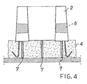
- the number 1 indicates, in its entirety, a prefabricated foundation plinth, comprising a main body or collar 2 having circular or oval cross section and defining within it a cavity 3, preferably with cubic or parallelepiped shape, shown in figure 1 , into which a pillar is installed.
- the main body thus has an original outer shape, substantially cylindrical or cone frustum with the lower base upwards.
- the plinth further comprises a base or slab 4 made of reinforced concrete for discharging the stresses on the ground, which slab is an ordinary plinth base able to withstand combined compressive and bending stresses as well as the punching by the pillar-plinth complex.
- the plinth 1 is a monolithic prefabricated plinth, i.e. one in which main body and slab are prefabricated in a single piece.
- the plinth can also be monolithic in place, i.e. with main body and slab cast in place to form a single piece.
- the main body of the plinth defines four blind holes 8, positioned at 90° and of a substantially known type, separated by a thin baffle from the central cavity 3. As the need dictates, it is easy to break one of the baffles to open one of the holes 8 creating a communication between the cavity 3 and the exterior of the plinth, through which cables can be passed, for example.
- the plinth may also be constituted by a prefabricated main body that couples with a slab cast in place.
- three irons 7 are used, preferably with 30 mm diameter, to hold the main body stably in position while casting the slab.
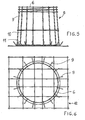
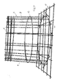
- the main body 2 is reinforced by a cage 5 originally constituted by individual vertical and sub-vertical irons 9, whose function is to collaborate with the concrete to generate and adequate resistance to axial and/or flexion stresses.
- the irons 9 have 12-20 mm diameter and they are inferiorly bent for anchoring to the slab.
- the main body 2 further comprises a spiral 6, preferably made of reinforcement steel having 10-16 mm diameter, which in addition to restraining the irons described above, serves the purpose of withstanding tangential (horizontal) and/or torsion stresses.
- the spiral 6 has substantially transverse development.
- the spiral 6, at three or more turns with fixed pitch or with variable pitch, is positioned in the upper part of the main body, whilst in the intermediate part of the main body is present an intermediate hoop 10 preferably with a single turn and in the lower part there can be a base hoop 11 to facilitate assembling the slab and the main body.
- the present invention has the advantage of presenting a single spiral reinforcement and single hoops instead of a double bracket reinforcement, with consequent saving of about 30% of the ferrous material employed and about 50% of the time necessary to install the plinth, both thanks to the smaller quantity of ferrous material used, and because the spiral and the hoops are obtained from iron already bent circularly because it is wound on reels, whilst traditional double bracket reinforcements, with the irons bent repeatedly to describe substantially rectangular shapes, need more time for working and bending the iron. This allows for evident savings in the costs of manufacture of the plinth.
- An additional advantage is that the particular cylindrical or cone frustum shape of the main body 2 of the plinth, having perfect symmetry, allows for better functionality of the plinth with respect to stresses.
Landscapes
- Engineering & Computer Science (AREA)
- Architecture (AREA)
- Civil Engineering (AREA)
- Structural Engineering (AREA)
- Rod-Shaped Construction Members (AREA)
Priority Applications (1)
| Application Number | Priority Date | Filing Date | Title |
|---|---|---|---|
| EP08425694A EP2182142A1 (de) | 2008-10-29 | 2008-10-29 | Sockel |
Applications Claiming Priority (1)
| Application Number | Priority Date | Filing Date | Title |
|---|---|---|---|
| EP08425694A EP2182142A1 (de) | 2008-10-29 | 2008-10-29 | Sockel |
Publications (1)
| Publication Number | Publication Date |
|---|---|
| EP2182142A1 true EP2182142A1 (de) | 2010-05-05 |
Family
ID=40469794
Family Applications (1)
| Application Number | Title | Priority Date | Filing Date |
|---|---|---|---|
| EP08425694A Withdrawn EP2182142A1 (de) | 2008-10-29 | 2008-10-29 | Sockel |
Country Status (1)
| Country | Link |
|---|---|
| EP (1) | EP2182142A1 (de) |
Citations (12)
| Publication number | Priority date | Publication date | Assignee | Title |
|---|---|---|---|---|
| US1433621A (en) * | 1921-01-08 | 1922-10-31 | Leopold Claude Constable | Reenforced anchors made of plastic and semiplastic material |
| DE970887C (de) * | 1953-01-04 | 1958-11-06 | Starkstromanlagen Ag | Mastfundament aus einzelnen Stahlbetonstaeben |
| GB1029796A (en) * | 1963-08-09 | 1966-05-18 | John Bolton | Improvements relating to reinforced concrete structures of extended columnar form |
| DE3931560A1 (de) * | 1989-09-22 | 1991-04-04 | Nh Beton Gmbh | Arkadensystem |
| US5169111A (en) * | 1992-03-18 | 1992-12-08 | Dunaj Raymond C | Collapsible stand for shade umbrellas |
| US5257489A (en) * | 1991-10-15 | 1993-11-02 | Angelette A M | Railroad crossing signal foundation |
| WO1999028562A1 (de) * | 1997-11-26 | 1999-06-10 | Bernard Douet | Säulenfundament in gebäuden, bauwerken od. dgl. |
| DE20015251U1 (de) * | 2000-09-01 | 2001-01-18 | Ernst Doppler & Co. Gmbh, Braunau | Standfuß zur Aufnahme von Masten |
| DE10030966A1 (de) * | 1999-11-09 | 2001-05-10 | Heiner Koch | Vorrichtung zum Montieren und Verankern von Pfosten, Stützen o. dgl. |
| RU2246585C2 (ru) * | 2002-12-24 | 2005-02-20 | Открытое акционерное общество "Научно-исследовательский институт транспортного строительства (ЦНИИС)" | Буроинъекционная свая |
| DE202006006125U1 (de) * | 2006-04-15 | 2006-07-20 | Vetter Fördertechnik GmbH | Verankerung von Säulen für Säulenschwenkkrane und Werbesäulen |
| US20070224002A1 (en) * | 2006-03-23 | 2007-09-27 | Richard Scholl | Assembly and method for protecting a pier and a post combination |
-
2008
- 2008-10-29 EP EP08425694A patent/EP2182142A1/de not_active Withdrawn
Patent Citations (12)
| Publication number | Priority date | Publication date | Assignee | Title |
|---|---|---|---|---|
| US1433621A (en) * | 1921-01-08 | 1922-10-31 | Leopold Claude Constable | Reenforced anchors made of plastic and semiplastic material |
| DE970887C (de) * | 1953-01-04 | 1958-11-06 | Starkstromanlagen Ag | Mastfundament aus einzelnen Stahlbetonstaeben |
| GB1029796A (en) * | 1963-08-09 | 1966-05-18 | John Bolton | Improvements relating to reinforced concrete structures of extended columnar form |
| DE3931560A1 (de) * | 1989-09-22 | 1991-04-04 | Nh Beton Gmbh | Arkadensystem |
| US5257489A (en) * | 1991-10-15 | 1993-11-02 | Angelette A M | Railroad crossing signal foundation |
| US5169111A (en) * | 1992-03-18 | 1992-12-08 | Dunaj Raymond C | Collapsible stand for shade umbrellas |
| WO1999028562A1 (de) * | 1997-11-26 | 1999-06-10 | Bernard Douet | Säulenfundament in gebäuden, bauwerken od. dgl. |
| DE10030966A1 (de) * | 1999-11-09 | 2001-05-10 | Heiner Koch | Vorrichtung zum Montieren und Verankern von Pfosten, Stützen o. dgl. |
| DE20015251U1 (de) * | 2000-09-01 | 2001-01-18 | Ernst Doppler & Co. Gmbh, Braunau | Standfuß zur Aufnahme von Masten |
| RU2246585C2 (ru) * | 2002-12-24 | 2005-02-20 | Открытое акционерное общество "Научно-исследовательский институт транспортного строительства (ЦНИИС)" | Буроинъекционная свая |
| US20070224002A1 (en) * | 2006-03-23 | 2007-09-27 | Richard Scholl | Assembly and method for protecting a pier and a post combination |
| DE202006006125U1 (de) * | 2006-04-15 | 2006-07-20 | Vetter Fördertechnik GmbH | Verankerung von Säulen für Säulenschwenkkrane und Werbesäulen |
Similar Documents
| Publication | Publication Date | Title |
|---|---|---|
| KR100999020B1 (ko) | 합성 피에이취씨 말뚝 및 합성 피에이취씨 말뚝 시공방법 | |
| CA2916228C (en) | Pre-cast concrete foundation of modular construction for telecommunication or wind turbine tower | |
| US20040134144A1 (en) | Use of partial precast panels for construction of concrete walls and shells | |
| JP2005180082A (ja) | コンクリートタワー | |
| CN209293235U (zh) | 预制剪力墙体及装配式建筑结构体系 | |
| CN110499823A (zh) | 一种稳定性高的装配式建筑框架结构及其装配方法 | |
| JP2016191289A (ja) | 杭頭接合部材及びこれを用いた杭頭接合構造 | |
| KR101797121B1 (ko) | 내진기능을 갖는 원형탱크 | |
| CN102587406A (zh) | 一种混凝土填充式塔吊基础格构柱的浇筑施工方法 | |
| KR100717766B1 (ko) | 슬래브용 중공관 유닛 및 이를 포함한 슬래브 | |
| JPH1018424A (ja) | 鉄骨柱等の柱脚部の根巻き型補強構造 | |
| KR20160143269A (ko) | 조립식 파일용 두부 보강캡 | |
| KR102003110B1 (ko) | 돔 건축물의 철골구조 | |
| JPH0387420A (ja) | 建造物の柱体立設構造 | |
| CN208441313U (zh) | 一种h型钢结构叠合楼板 | |
| CN220013752U (zh) | 密封式支撑格构柱 | |
| JP5844579B2 (ja) | 塔状構造物 | |
| CN203569700U (zh) | 一种钢管混凝土组合柱向钢筋混凝土柱的过渡节点 | |
| CN208294064U (zh) | 一种用于多连体薄壁筒仓滑模系统的固定结构 | |
| CN208870236U (zh) | 一种构造柱顶部与主体结构连接装置 | |
| KR200233599Y1 (ko) | 교각의 철근 설치구조 | |
| KR20190107317A (ko) | 일체형형강을 이용한 프리캐스트 이중벽체구조물 제작방법 및 그 시공방법 | |
| ITPR20070032A1 (it) | Plinto | |
| JP5562660B2 (ja) | プレストレストコンクリート構造物 | |
| KR200462544Y1 (ko) | 조립식 건축 기둥 구조물 |
Legal Events
| Date | Code | Title | Description |
|---|---|---|---|
| PUAI | Public reference made under article 153(3) epc to a published international application that has entered the european phase |
Free format text: ORIGINAL CODE: 0009012 |
|
| AK | Designated contracting states |
Kind code of ref document: A1 Designated state(s): AT BE BG CH CY CZ DE DK EE ES FI FR GB GR HR HU IE IS IT LI LT LU LV MC MT NL NO PL PT RO SE SI SK TR |
|
| AX | Request for extension of the european patent |
Extension state: AL BA MK RS |
|
| 17P | Request for examination filed |
Effective date: 20100922 |
|
| AKX | Designation fees paid |
Designated state(s): AT BE BG CH CY CZ DE DK EE ES FI FR GB GR HR HU IE IS IT LI LT LU LV MC MT NL NO PL PT RO SE SI SK TR |
|
| 17Q | First examination report despatched |
Effective date: 20101221 |
|
| STAA | Information on the status of an ep patent application or granted ep patent |
Free format text: STATUS: THE APPLICATION IS DEEMED TO BE WITHDRAWN |
|
| 18D | Application deemed to be withdrawn |
Effective date: 20131206 |