EP2182174A2 - Steam turbine with pressure activated sealing device - Google Patents
Steam turbine with pressure activated sealing device Download PDFInfo
- Publication number
- EP2182174A2 EP2182174A2 EP09173962A EP09173962A EP2182174A2 EP 2182174 A2 EP2182174 A2 EP 2182174A2 EP 09173962 A EP09173962 A EP 09173962A EP 09173962 A EP09173962 A EP 09173962A EP 2182174 A2 EP2182174 A2 EP 2182174A2
- Authority
- EP
- European Patent Office
- Prior art keywords
- outer ring
- seal
- diaphragm outer
- piston
- gap closure
- Prior art date
- Legal status (The legal status is an assumption and is not a legal conclusion. Google has not performed a legal analysis and makes no representation as to the accuracy of the status listed.)
- Withdrawn
Links
Images


Classifications
-
- F—MECHANICAL ENGINEERING; LIGHTING; HEATING; WEAPONS; BLASTING
- F01—MACHINES OR ENGINES IN GENERAL; ENGINE PLANTS IN GENERAL; STEAM ENGINES
- F01D—NON-POSITIVE DISPLACEMENT MACHINES OR ENGINES, e.g. STEAM TURBINES
- F01D11/00—Preventing or minimising internal leakage of working-fluid, e.g. between stages
- F01D11/08—Preventing or minimising internal leakage of working-fluid, e.g. between stages for sealing space between rotor blade tips and stator
- F01D11/14—Adjusting or regulating tip-clearance, i.e. distance between rotor-blade tips and stator casing
- F01D11/20—Actively adjusting tip-clearance
- F01D11/22—Actively adjusting tip-clearance by mechanically actuating the stator or rotor components, e.g. moving shroud sections relative to the rotor
-
- F—MECHANICAL ENGINEERING; LIGHTING; HEATING; WEAPONS; BLASTING
- F01—MACHINES OR ENGINES IN GENERAL; ENGINE PLANTS IN GENERAL; STEAM ENGINES
- F01D—NON-POSITIVE DISPLACEMENT MACHINES OR ENGINES, e.g. STEAM TURBINES
- F01D11/00—Preventing or minimising internal leakage of working-fluid, e.g. between stages
- F01D11/02—Preventing or minimising internal leakage of working-fluid, e.g. between stages by non-contact sealings, e.g. of labyrinth type
- F01D11/025—Seal clearance control; Floating assembly; Adaptation means to differential thermal dilatations
-
- F—MECHANICAL ENGINEERING; LIGHTING; HEATING; WEAPONS; BLASTING
- F01—MACHINES OR ENGINES IN GENERAL; ENGINE PLANTS IN GENERAL; STEAM ENGINES
- F01D—NON-POSITIVE DISPLACEMENT MACHINES OR ENGINES, e.g. STEAM TURBINES
- F01D11/00—Preventing or minimising internal leakage of working-fluid, e.g. between stages
- F01D11/08—Preventing or minimising internal leakage of working-fluid, e.g. between stages for sealing space between rotor blade tips and stator
- F01D11/12—Preventing or minimising internal leakage of working-fluid, e.g. between stages for sealing space between rotor blade tips and stator using a rubstrip, e.g. erodible. deformable or resiliently-biased part
-
- F—MECHANICAL ENGINEERING; LIGHTING; HEATING; WEAPONS; BLASTING
- F01—MACHINES OR ENGINES IN GENERAL; ENGINE PLANTS IN GENERAL; STEAM ENGINES
- F01D—NON-POSITIVE DISPLACEMENT MACHINES OR ENGINES, e.g. STEAM TURBINES
- F01D11/00—Preventing or minimising internal leakage of working-fluid, e.g. between stages
- F01D11/08—Preventing or minimising internal leakage of working-fluid, e.g. between stages for sealing space between rotor blade tips and stator
- F01D11/14—Adjusting or regulating tip-clearance, i.e. distance between rotor-blade tips and stator casing
- F01D11/16—Adjusting or regulating tip-clearance, i.e. distance between rotor-blade tips and stator casing by self-adjusting means
-
- F—MECHANICAL ENGINEERING; LIGHTING; HEATING; WEAPONS; BLASTING
- F01—MACHINES OR ENGINES IN GENERAL; ENGINE PLANTS IN GENERAL; STEAM ENGINES
- F01D—NON-POSITIVE DISPLACEMENT MACHINES OR ENGINES, e.g. STEAM TURBINES
- F01D5/00—Blades; Blade-carrying members; Heating, heat-insulating, cooling or antivibration means on the blades or the members
- F01D5/12—Blades
- F01D5/22—Blade-to-blade connections, e.g. for damping vibrations
- F01D5/225—Blade-to-blade connections, e.g. for damping vibrations by shrouding
-
- F—MECHANICAL ENGINEERING; LIGHTING; HEATING; WEAPONS; BLASTING
- F05—INDEXING SCHEMES RELATING TO ENGINES OR PUMPS IN VARIOUS SUBCLASSES OF CLASSES F01-F04
- F05D—INDEXING SCHEME FOR ASPECTS RELATING TO NON-POSITIVE-DISPLACEMENT MACHINES OR ENGINES, GAS-TURBINES OR JET-PROPULSION PLANTS
- F05D2220/00—Application
- F05D2220/30—Application in turbines
- F05D2220/31—Application in turbines in steam turbines
Definitions
- the present invention relates generally to seals between rotatary and stationary components of a steam turbine and more particularly to a seal activated by a pressure differential formed across the rotary component and the stationary component of a steam turbine.
- a seal between rotary and stationary components is an important part of the steam turbine performance. It will be appreciated that the greater the number and magnitude of steam leakage paths, the greater the losses of efficiency of the steam turbine.
- labyrinth seal teeth often used to seal between the diaphragms of the stationary component and the rotor or between the rotor bucket tips and the stationary shroud of the rotary component require substantial clearances to be maintained to allow for radial and circumferential movement during transient operations such as startup and shutdown of the steam turbine. These clearances are, of course, detrimental to sealing. There are also clearance issues associated with multiple independent seal surfaces, tolerance stack up of radial clearances and assembly of multiple seals, all of which can diminish steam turbine efficiency. Moreover, it is often difficult to create seals which not only increase the efficiency of the steam turbine but also increase the ability to service and repair various parts of the turbine as well as to create known repeatable boundary conditions for such parts.
- a steam turbine comprising a rotary component including a plurality of circumferentially spaced buckets that are spaced at axial positions. Each of the plurality of buckets has a tip with an adjacent cover that includes one or more seal teeth.
- the steam turbine further comprises a stationary component that includes a plurality of diaphragms each having a diaphragm outer ring and an inner diaphragm ring separated by a mounting partition. The plurality of diaphragms are axially positioned between adjacent rows of the plurality of buckets. Each row forms a turbine stage that defines a portion of a steam flow path through the turbine.
- Each diaphragm outer ring has a passage formed therein that connects a high pressure end to a low pressure end.
- the steam turbine further comprises a gap closure component located about the rotary component and the stationary component that seals a portion of a steam leakage path.
- the gap closure component includes a plurality of gap closure devices. Each of the plurality of gap closure devices is located about each respective diaphragm outer ring and one or more seal teeth of a bucket cover. Each of the plurality of gap closure devices is activated by a pressure differential formed across the passage of a respective diaphragm outer ring that provides a seal of the steam leakage path through the one or more seal teeth of the bucket cover and the diaphragm outer ring.
- Rotary component 105 includes, for example a rotor 115 mounting a plurality of circumferentially spaced buckets 120 at spaced axial positions along the turbine forming parts of the various turbine stages.
- Stationary component 110 including a plurality of diaphragms 125 mounting partitions 130 defining nozzles which, together with respective buckets, form the various stages of steam turbine 100.
- an outer ring 135 of the diaphragm 125 carries one or more rows of seal teeth 140 for sealing with shrouds or covers 145 adjacent the tips of buckets 120.
- an inner ring 150 of diaphragm 125 mounts an arcuate seal segment 155.
- the seal segment has radially inwardly projecting high-low teeth 160 for sealing with rotor 115. Similar seals are provided at the various stages of steam turbine 100 as illustrated and the direction of the steam flow path is indicated by the arrow 165.
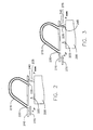
- FIG. 2 is a schematic cross-sectional view of a gap closure component according to a first embodiment of the present invention.
- FIG. 2 like FIGS. 3-12 show only portions of the rotary component and stationary component of the steam turbine depicted from FIG. 1 that are necessary to explain the operation of the various gap closure devices described herein.
- FIG. 2 shows a bucket tip and cover 200 with seal teeth 205 for the rotary component of the steam turbine and a diaphragm outer ring 210 for the stationary component of the steam turbine.
- Diaphragm 210 includes a passage 215 formed therein that connects a high pressure end 220 of a turbine stage to a low pressure end 225 of the turbine stage.
- passage 215 preferably is a channel formed in diaphragm outer ring 210 that provides an alternative path for leakage from steam flow path 230 to travel as it flows from a high pressure upstream location (P UP ) to a low pressure downstream location (P DOWN ).
- the pressure at low pressure end 225 is lower than that at high pressure end 220 or where steam flow path 230 is designated.
- the pressure is lower due to the pressure drop over the first seal tooth 205. It is this differential, i.e., the pressure difference between the high pressure end 220 and low pressure end 225 that forces a gap closure component (e.g., a flap seal 235) to open and/or close.
- a gap closure component e.g., a flap seal 235
- passage 215 is shown in FIG. 2 as being U-shaped, those skilled in the art will recognize that other shaped passages may be utilized for moving steam flow path 230 from high pressure end 220 to low pressure end 225.
- the gap closure component of the embodiment shown in FIG. 2 includes flap seal 235 hinged to diaphragm outer ring 210 near low pressure end 225 of passage 215 by a hinge 240.
- Flap seal 235 as shown in FIG. 2 is at rest or in the inactive state. That is, a pressure differential has not formed across high pressure end 220 and low pressure end 225.
- FIG. 3 shows flap seal 235 in an activated state when the pressure differential has formed. In the activated state as shown in FIG. 3 , flap seal 235 moves away from low pressure end 225 of passage 215 to cover a seal tooth 205 of the bucket cover 200.
- flap seal 235 covers a face 245 of seal tooth 205 that is exposed to a region of high pressure of a steam leakage path. This enables flap seal 235 to cover the gap that exists between seal tooth 205 and the outboard static part of the stationary component.
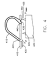
- FIG. 4 is a schematic cross-sectional view of a gap closure component according to a second embodiment of the present invention. Parts in FIG. 4 that are similar to parts used in FIGS. 2-3 are applied with like reference elements, except that the reference elements used in FIG. 4 are preceded with the numeral 4.
- the gap closure component of the embodiment shown in FIG. 4 is a flap seal 435 that comprises a bellow bend 440 welded at one end and a vertical lip 445 at an end opposite therefrom.
- bellow bend 440 mates with seal tooth 405 in the presence of the pressure differential and vertical lip 445 contacts low pressure end 425 of passage 415 in the absence of the pressure differential. Bellows bend 440 will lower the spring constant and stresses of the flap seal, while vertical lip 445 helps contain pressure and prevent flutter of the flap seal.
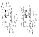
- FIG. 5 is a schematic cross-sectional view of a gap closure component according to a third embodiment of the present invention. Parts in FIG. 5 that are similar to parts used in FIGS. 2-3 are applied with like reference elements, except that the reference elements used in FIG. 5 are preceded with the numeral 5.
- the gap closure component of the embodiment shown in FIG. 5 comprises a piston 535 placed in a groove 540 of the diaphragm outer ring 510 at a low pressure end 525 of the passage 515.
- passage 515 of FIG. 5 is not shown in full as in the previous figures.
- curved springs 545 there are a plurality of curved springs 545 that each abut a top section 550 and bottom section 555 at opposing ends of an upper portion 560 of piston 535 and a portion of groove 540 of the diaphragm outer ring 510.
- this embodiment may operate without the use of the upper curved springs 545 as long as the lower curved springs 545 are well-designed.
- the function of the upper curved springs 545 is to position the piston 535 and keep the assembly from rattling around.
- Upper curved springs 545 also help balance the load so that a lower pressure difference can activate the seal.
- Lower curved springs 545 are used to return piston 535 to its original position in the absence of a pressure differential.
- a secondary function of the curved springs 545 is to seal the gaps around piston 535.
- Piston 535 as shown in FIG. 5 is at rest or in the inactive state. That is, a pressure differential has not formed across high pressure end 520 and low pressure end 525 of passage 515.
- FIG. 6 shows piston 535 in an activated state when the pressure differential has formed. In the activated state as shown in FIG. 6 , the presence of the pressure differential unbalances the load of plurality of curved springs 545 forcing piston 535 in steam flow path 530 through the seal teeth 505 of the bucket cover 500 and the diaphragm outer ring 510.
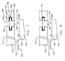
- FIG. 7 is a schematic cross-sectional view of a gap closure component according to a fourth embodiment of the present invention. Parts in FIG. 7 that are similar to parts used in FIGS. 5-6 are applied with like reference elements, except that the reference elements used in FIG. 7 are preceded with the numeral 7.
- two two-sided springs 775 are used to abut a top section 780, a side section 785 and a bottom section 790 of an upper portion 760 of piston 735 and a portion of the groove 740 of the diaphragm outer ring 710.
- the two two-sided springs 775 clip on side sections 785. In this configuration, parts count is reduced as compared to the embodiment shown in FIGS 5-6 and the possibility of misaligned springs is reduced.
- Piston 735 as shown in FIG. 7 is at rest or in the inactive state. That is, a pressure differential has not formed across high pressure end 720 and low pressure end 725 of passage 715.
- FIG. 8 shows piston 735 in an activated state when the pressure differential has formed. In the activated state as shown in FIG. 8 , the presence of the pressure differential unbalances the load of the two-sided springs 775 forcing piston 735 in a steam leakage path emanating from steam flow path 730 through the seal teeth 705 of the bucket cover 700 and the diaphragm outer ring 710. Like the embodiment described with reference to FIGS. 5-6 , it is possible to even use only one two-side spring 775 or not any spring at all.
- FIG. 9 is a schematic cross-sectional view of a gap closure component according to a fifth embodiment of the present invention. Parts in FIG. 9 that are similar to parts used in FIGS. 5-6 are applied with like reference elements, except that the reference elements used in FIG. 9 are preceded with the numeral 9.
- elastomeric elements 975 are used to abut a bottom section 980 of an upper portion 960 of piston 935 and a portion of groove 940 of diaphragm outer ring 910.
- elastomeric elements 975 may be comprised of various shapes and be either solid or hollow.
- a non-exhaustive list of possible elastomeric materials that can be used in this embodiment for low-temperature stages of the steam turbine include VITON (400 degrees Fahrenheit), which is a registered trademark of DuPont Dow Elastomers and SILASTIC (600 degrees Fahrenheit), which is a registered trademark of Dow Coming Corporation.
- Piston 935 as shown in FIG. 9 is at rest or in the inactive state. That is, a pressure differential has not formed across high pressure end 920 and low pressure end 925 of passage 915.
- FIG. 10 shows piston 935 in an activated state when the pressure differential has formed. In the activated state as shown in FIG. 10 , the presence of the pressure differential unbalances the load of the elastomeric elements 975 forcing piston 935 in a steam leakage path emanating from steam flow path through the one or more seal teeth 905 of the bucket cover 900 and the diaphragm outer ring 910.
- elastomeric element 975 it is possible to use only one elastomeric element 975. Further, in another embodiment, it may be possible to have a gap closure component that does not utilize any elastomeric element. In this embodiment, pistons in the bottom half of the turbine would not need a return mechanism because gravity would cause them to return to their initial position.
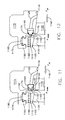
- FIGS. 11-12 are schematic cross-sectional views of a gap closure device according to a sixth embodiment of the present invention.
- FIGS. 11-12 are similar to FIGS. 3-10 in that only a simplified illustration of a steam turbine is shown, however, FIGS. 11-12 show some more detail of the rotary and stationary components of a steam turbine.
- FIGS. 11-12 show a bucket 1100 having a tip cover 1105 with seal teeth 1110 for the rotary component and a diaphragm outer ring 1115 and mounting partitions 1120 for the stationary component.
- Diaphragm outer ring 1115 includes a passage 1125 formed therein that connects a high pressure end 1130 of a turbine stage to a low pressure end 1135 of the turbine stage.
- passage 1125 preferably is a channel formed in diaphragm outer ring 1115 that provides an alternative path for steam flow path 1140 to travel as it flows from a high pressure upstream location (P UP ) to a low pressure downstream location (P DOWN ).
- the gap closure component of the embodiment shown in FIGS. 11-12 comprises a piston 1145 placed in a groove 1150 of the diaphragm outer ring 1115 at low pressure end 1135 of passage 1125 that acts axial.
- Piston 1145 comprises a top portion 1155 and a bottom portion 1160.
- Top portion 1155 has a larger volume than bottom portion 1160.
- bottom portion 1160 has one or more seal teeth 1165 projecting outward therefrom.
- the one or more seal teeth 1165 projecting outward from the bottom 1160 of piston 1145 are forced in a steam leakage path through the one or more seal teeth 1110 of the bucket cover 1105 and the diaphragm outer ring 1115 in the presence of the pressure differential as shown in FIG. 12 . More specifically, a single seal tooth 1105 sticks out from the bucket in the axial direction.
- the piston-activated seal provided by piston 1145 overlaps the axial tooth 1110 coming off the bucket to further block flow and create a tortuous path for leakage flow.
- FIGS. 11-12 further show that the gap closure component of this embodiment comprises at least two spring elements 1170.
- FIGS. 11-12 disclose the use of two spring elements, it is possible to utilize only spring element, no spring elements or use a similar functioning device therefore (elastomeric elements).
- the presence of the pressure differential unbalances the load of the two spring elements 1170 forcing the one or more seal teeth 1165 to project outward from the bottom of the piston 1145 forced in the steam leakage path through the one or more seal teeth 1110 of the bucket cover 1105 and the diaphragm outer ring 1115.
- the seal of this embodiment may work with only one spring element 1170 and thus this embodiment is not limited by the number of spring elements shown in FIGS. 11-12 .
- An additional element shown in the embodiment of FIGS. 11-12 includes a seal carrier 1175 having one or more seal teeth 1180 located in a groove 1185 of an extension 1190 of the diaphragm outer ring 1115.
- Seal carrier 1175 is radial with respect to the one or more seal teeth 1110 of the bucket cover 1105.
- Seal carrier 1175 also servers to provide a seal of the seal path flowing through the rotary component and stationary component of the steam turbine.
Landscapes
- Engineering & Computer Science (AREA)
- Mechanical Engineering (AREA)
- General Engineering & Computer Science (AREA)
- Turbine Rotor Nozzle Sealing (AREA)
Abstract
Description
- The present invention relates generally to seals between rotatary and stationary components of a steam turbine and more particularly to a seal activated by a pressure differential formed across the rotary component and the stationary component of a steam turbine.
- In a steam turbine, a seal between rotary and stationary components is an important part of the steam turbine performance. It will be appreciated that the greater the number and magnitude of steam leakage paths, the greater the losses of efficiency of the steam turbine. For example, labyrinth seal teeth often used to seal between the diaphragms of the stationary component and the rotor or between the rotor bucket tips and the stationary shroud of the rotary component require substantial clearances to be maintained to allow for radial and circumferential movement during transient operations such as startup and shutdown of the steam turbine. These clearances are, of course, detrimental to sealing. There are also clearance issues associated with multiple independent seal surfaces, tolerance stack up of radial clearances and assembly of multiple seals, all of which can diminish steam turbine efficiency. Moreover, it is often difficult to create seals which not only increase the efficiency of the steam turbine but also increase the ability to service and repair various parts of the turbine as well as to create known repeatable boundary conditions for such parts.
- In one aspect of the present invention, a steam turbine is provided. The steam turbine comprises a rotary component including a plurality of circumferentially spaced buckets that are spaced at axial positions. Each of the plurality of buckets has a tip with an adjacent cover that includes one or more seal teeth. The steam turbine further comprises a stationary component that includes a plurality of diaphragms each having a diaphragm outer ring and an inner diaphragm ring separated by a mounting partition. The plurality of diaphragms are axially positioned between adjacent rows of the plurality of buckets. Each row forms a turbine stage that defines a portion of a steam flow path through the turbine. Each diaphragm outer ring has a passage formed therein that connects a high pressure end to a low pressure end. The steam turbine further comprises a gap closure component located about the rotary component and the stationary component that seals a portion of a steam leakage path. The gap closure component includes a plurality of gap closure devices. Each of the plurality of gap closure devices is located about each respective diaphragm outer ring and one or more seal teeth of a bucket cover. Each of the plurality of gap closure devices is activated by a pressure differential formed across the passage of a respective diaphragm outer ring that provides a seal of the steam leakage path through the one or more seal teeth of the bucket cover and the diaphragm outer ring.
- There follows a detailed description of embodiments of the invention by way of example only with reference to the accompanying drawings, in which:
-
FIG. 1 is a fragmentary cross-sectional view of a portion of a steam turbine illustrating various seals according to the prior art; -
FIG. 2 is a schematic cross-sectional view of a gap closure device according to a first embodiment of the present invention; -
FIG. 3 is a schematic cross-sectional view showing the gap closure device ofFIG. 2 in an activated state in the presence of a pressure differential; -
FIG. 4 is a schematic cross-sectional view of a gap closure device according to a second embodiment of the present invention; -
FIG. 5 is a schematic cross-sectional view of a gap closure device according to a third embodiment of the present invention; -
FIG. 6 is a schematic cross-sectional view showing the gap closure device ofFIG. 5 in an activated state in the presence of a pressure differential; -
FIG. 7 is a schematic cross-sectional view of a gap closure device according to a fourth embodiment of the present invention; -
FIG. 8 is a schematic cross-sectional view showing the gap closure device ofFIG. 7 in an activated state in the presence of a pressure differential; -
FIG. 9 is a schematic cross-sectional view of a gap closure device according to a fifth embodiment of the present invention; -
FIG. 10 is a schematic cross-sectional view showing the gap closure device ofFIG. 9 in an activated state in the presence of a pressure differential; -
FIG. 11 is a schematic cross-sectional view of a gap closure device according to a sixth embodiment of the present invention; and -
FIG. 12 is a schematic cross-sectional view showing the gap closure device ofFIG. 11 in an activated state in the presence of a pressure differential. - Referring now to the figures, particularly to
FIG. 1 , there is illustrated a portion of asteam turbine 100 having arotary component 105 and astationary component 110.Rotary component 105 includes, for example arotor 115 mounting a plurality of circumferentially spacedbuckets 120 at spaced axial positions along the turbine forming parts of the various turbine stages.Stationary component 110 including a plurality ofdiaphragms 125mounting partitions 130 defining nozzles which, together with respective buckets, form the various stages ofsteam turbine 100. As illustrated inFIG. 1 , anouter ring 135 of thediaphragm 125 carries one or more rows ofseal teeth 140 for sealing with shrouds or covers 145 adjacent the tips ofbuckets 120. Similarly, aninner ring 150 ofdiaphragm 125 mounts anarcuate seal segment 155. The seal segment has radially inwardly projecting high-low teeth 160 for sealing withrotor 115. Similar seals are provided at the various stages ofsteam turbine 100 as illustrated and the direction of the steam flow path is indicated by thearrow 165. -
FIG. 2 is a schematic cross-sectional view of a gap closure component according to a first embodiment of the present invention.FIG. 2 , likeFIGS. 3-12 show only portions of the rotary component and stationary component of the steam turbine depicted fromFIG. 1 that are necessary to explain the operation of the various gap closure devices described herein. In particular,FIG. 2 shows a bucket tip and cover 200 withseal teeth 205 for the rotary component of the steam turbine and a diaphragmouter ring 210 for the stationary component of the steam turbine.Diaphragm 210 includes apassage 215 formed therein that connects ahigh pressure end 220 of a turbine stage to alow pressure end 225 of the turbine stage. In this embodiment,passage 215 preferably is a channel formed in diaphragmouter ring 210 that provides an alternative path for leakage fromsteam flow path 230 to travel as it flows from a high pressure upstream location (PUP) to a low pressure downstream location (PDOWN). The pressure atlow pressure end 225 is lower than that athigh pressure end 220 or wheresteam flow path 230 is designated. The pressure is lower due to the pressure drop over thefirst seal tooth 205. It is this differential, i.e., the pressure difference between thehigh pressure end 220 andlow pressure end 225 that forces a gap closure component (e.g., a flap seal 235) to open and/or close. Those skilled in the art will recognize that an even greater pressure differential can be had by locatinghigh pressure end 220 further upstream (e.g., ahead of the preceding nozzle stage). Similarly, those skilled in the art will recognize that this is equally applicable to the embodiments disclosed inFIGS. 3-10 . Althoughpassage 215 is shown inFIG. 2 as being U-shaped, those skilled in the art will recognize that other shaped passages may be utilized for movingsteam flow path 230 fromhigh pressure end 220 tolow pressure end 225. - As mentioned above, the gap closure component of the embodiment shown in
FIG. 2 includesflap seal 235 hinged to diaphragmouter ring 210 nearlow pressure end 225 ofpassage 215 by ahinge 240.Flap seal 235 as shown inFIG. 2 is at rest or in the inactive state. That is, a pressure differential has not formed acrosshigh pressure end 220 andlow pressure end 225.FIG. 3 showsflap seal 235 in an activated state when the pressure differential has formed. In the activated state as shown inFIG. 3 ,flap seal 235 moves away fromlow pressure end 225 ofpassage 215 to cover aseal tooth 205 of thebucket cover 200. In particular,flap seal 235 covers aface 245 ofseal tooth 205 that is exposed to a region of high pressure of a steam leakage path. This enablesflap seal 235 to cover the gap that exists betweenseal tooth 205 and the outboard static part of the stationary component. -
FIG. 4 is a schematic cross-sectional view of a gap closure component according to a second embodiment of the present invention. Parts inFIG. 4 that are similar to parts used inFIGS. 2-3 are applied with like reference elements, except that the reference elements used inFIG. 4 are preceded with the numeral 4. The gap closure component of the embodiment shown inFIG. 4 is aflap seal 435 that comprises abellow bend 440 welded at one end and avertical lip 445 at an end opposite therefrom. In this embodiment, bellow bend 440 mates withseal tooth 405 in the presence of the pressure differential andvertical lip 445 contactslow pressure end 425 ofpassage 415 in the absence of the pressure differential. Bellowsbend 440 will lower the spring constant and stresses of the flap seal, whilevertical lip 445 helps contain pressure and prevent flutter of the flap seal. -
FIG. 5 is a schematic cross-sectional view of a gap closure component according to a third embodiment of the present invention. Parts inFIG. 5 that are similar to parts used inFIGS. 2-3 are applied with like reference elements, except that the reference elements used inFIG. 5 are preceded with the numeral 5. The gap closure component of the embodiment shown inFIG. 5 comprises apiston 535 placed in agroove 540 of the diaphragmouter ring 510 at alow pressure end 525 of thepassage 515. For ease of illustration, note thatpassage 515 ofFIG. 5 is not shown in full as in the previous figures. In this embodiment, there are a plurality ofcurved springs 545 that each abut atop section 550 andbottom section 555 at opposing ends of anupper portion 560 ofpiston 535 and a portion ofgroove 540 of the diaphragmouter ring 510. Those skilled in the art will recognize that this embodiment may operate without the use of the uppercurved springs 545 as long as the lowercurved springs 545 are well-designed. Basically, the function of the uppercurved springs 545 is to position thepiston 535 and keep the assembly from rattling around. Uppercurved springs 545 also help balance the load so that a lower pressure difference can activate the seal. Lowercurved springs 545 are used to returnpiston 535 to its original position in the absence of a pressure differential. A secondary function of thecurved springs 545 is to seal the gaps aroundpiston 535. -
Piston 535 as shown inFIG. 5 is at rest or in the inactive state. That is, a pressure differential has not formed acrosshigh pressure end 520 andlow pressure end 525 ofpassage 515.FIG. 6 showspiston 535 in an activated state when the pressure differential has formed. In the activated state as shown inFIG. 6 , the presence of the pressure differential unbalances the load of plurality ofcurved springs 545 forcingpiston 535 insteam flow path 530 through theseal teeth 505 of thebucket cover 500 and the diaphragmouter ring 510. - In another embodiment, it is possible to even use only one
curved spring 545. Further, in another embodiment, it may be possible to have a gap closure component that does not utilize any curved springs. In this embodiment, pistons in the bottom half of the turbine would not need a return mechanism because gravity would cause them to return to their initial position. -
FIG. 7 is a schematic cross-sectional view of a gap closure component according to a fourth embodiment of the present invention. Parts inFIG. 7 that are similar to parts used inFIGS. 5-6 are applied with like reference elements, except that the reference elements used inFIG. 7 are preceded with the numeral 7. In the embodiment ofFIG. 7 , two two-sided springs 775 are used to abut atop section 780, aside section 785 and abottom section 790 of anupper portion 760 ofpiston 735 and a portion of thegroove 740 of the diaphragmouter ring 710. The two two-sided springs 775 clip onside sections 785. In this configuration, parts count is reduced as compared to the embodiment shown inFIGS 5-6 and the possibility of misaligned springs is reduced. -
Piston 735 as shown inFIG. 7 is at rest or in the inactive state. That is, a pressure differential has not formed acrosshigh pressure end 720 andlow pressure end 725 ofpassage 715.FIG. 8 showspiston 735 in an activated state when the pressure differential has formed. In the activated state as shown inFIG. 8 , the presence of the pressure differential unbalances the load of the two-sided springs 775 forcingpiston 735 in a steam leakage path emanating fromsteam flow path 730 through theseal teeth 705 of thebucket cover 700 and the diaphragmouter ring 710. Like the embodiment described with reference toFIGS. 5-6 , it is possible to even use only one two-side spring 775 or not any spring at all. -
FIG. 9 is a schematic cross-sectional view of a gap closure component according to a fifth embodiment of the present invention. Parts inFIG. 9 that are similar to parts used inFIGS. 5-6 are applied with like reference elements, except that the reference elements used inFIG. 9 are preceded with the numeral 9. In the embodiment ofFIG. 9 ,elastomeric elements 975 are used to abut abottom section 980 of anupper portion 960 ofpiston 935 and a portion ofgroove 940 of diaphragmouter ring 910. Those skilled in the art will recognize thatelastomeric elements 975 may be comprised of various shapes and be either solid or hollow. A non-exhaustive list of possible elastomeric materials that can be used in this embodiment for low-temperature stages of the steam turbine include VITON (400 degrees Fahrenheit), which is a registered trademark of DuPont Dow Elastomers and SILASTIC (600 degrees Fahrenheit), which is a registered trademark of Dow Coming Corporation. -
Piston 935 as shown inFIG. 9 is at rest or in the inactive state. That is, a pressure differential has not formed acrosshigh pressure end 920 andlow pressure end 925 ofpassage 915.FIG. 10 showspiston 935 in an activated state when the pressure differential has formed. In the activated state as shown inFIG. 10 , the presence of the pressure differential unbalances the load of theelastomeric elements 975 forcingpiston 935 in a steam leakage path emanating from steam flow path through the one ormore seal teeth 905 of thebucket cover 900 and the diaphragmouter ring 910. - In another embodiment, it is possible to use only one
elastomeric element 975. Further, in another embodiment, it may be possible to have a gap closure component that does not utilize any elastomeric element. In this embodiment, pistons in the bottom half of the turbine would not need a return mechanism because gravity would cause them to return to their initial position. -
FIGS. 11-12 are schematic cross-sectional views of a gap closure device according to a sixth embodiment of the present invention.FIGS. 11-12 are similar toFIGS. 3-10 in that only a simplified illustration of a steam turbine is shown, however,FIGS. 11-12 show some more detail of the rotary and stationary components of a steam turbine. In particular,FIGS. 11-12 show abucket 1100 having atip cover 1105 withseal teeth 1110 for the rotary component and a diaphragmouter ring 1115 and mountingpartitions 1120 for the stationary component. Diaphragmouter ring 1115 includes apassage 1125 formed therein that connects ahigh pressure end 1130 of a turbine stage to alow pressure end 1135 of the turbine stage. In this embodiment,passage 1125 preferably is a channel formed in diaphragmouter ring 1115 that provides an alternative path forsteam flow path 1140 to travel as it flows from a high pressure upstream location (PUP) to a low pressure downstream location (PDOWN). - The gap closure component of the embodiment shown in
FIGS. 11-12 comprises apiston 1145 placed in agroove 1150 of the diaphragmouter ring 1115 atlow pressure end 1135 ofpassage 1125 that acts axial.Piston 1145 comprises atop portion 1155 and abottom portion 1160.Top portion 1155 has a larger volume thanbottom portion 1160. In addition,bottom portion 1160 has one ormore seal teeth 1165 projecting outward therefrom. Those skilled in the art will recognize that this embodiment can work withpiston 1145 having only a single seal tooth, or without any seal teeth if desired. The one ormore seal teeth 1165 projecting outward from thebottom 1160 ofpiston 1145 are forced in a steam leakage path through the one ormore seal teeth 1110 of thebucket cover 1105 and the diaphragmouter ring 1115 in the presence of the pressure differential as shown inFIG. 12 . More specifically, asingle seal tooth 1105 sticks out from the bucket in the axial direction. The piston-activated seal provided bypiston 1145 overlaps theaxial tooth 1110 coming off the bucket to further block flow and create a tortuous path for leakage flow.FIGS. 11-12 further show that the gap closure component of this embodiment comprises at least twospring elements 1170. Eachspring element 1170 abuts the top portion and the bottom portion ofpiston 1145 and a portion ofgroove 1150 of the diaphragmouter ring 1115. AlthoughFIGS. 11-12 disclose the use of two spring elements, it is possible to utilize only spring element, no spring elements or use a similar functioning device therefore (elastomeric elements). As shown inFIG. 12 , the presence of the pressure differential unbalances the load of the twospring elements 1170 forcing the one ormore seal teeth 1165 to project outward from the bottom of thepiston 1145 forced in the steam leakage path through the one ormore seal teeth 1110 of thebucket cover 1105 and the diaphragmouter ring 1115. Those skilled in the art will recognize that the seal of this embodiment may work with only onespring element 1170 and thus this embodiment is not limited by the number of spring elements shown inFIGS. 11-12 . - An additional element shown in the embodiment of
FIGS. 11-12 includes aseal carrier 1175 having one ormore seal teeth 1180 located in agroove 1185 of anextension 1190 of the diaphragmouter ring 1115.Seal carrier 1175 is radial with respect to the one ormore seal teeth 1110 of thebucket cover 1105.Seal carrier 1175 also servers to provide a seal of the seal path flowing through the rotary component and stationary component of the steam turbine. - While the disclosure has been particularly shown and described in conjunction with a preferred embodiment thereof, it will be appreciated that variations and modifications will occur to those skilled in the art. Therefore, it is to be understood that the appended claims are intended to cover all such modifications and changes as fall within the true spirit of the disclosure.
Claims (11)
- A steam turbine (100), comprising:a rotary component (105) including a plurality of circumferentially spaced buckets that are spaced at axial positions, each of the plurality of buckets having a tip with an adjacent cover that includes one or more seal teeth;a stationary component (110) including a plurality of diaphragms each having a diaphragm outer ring and an inner diaphragm ring separated by a mounting partition, the plurality of diaphragms are axially positioned between adjacent rows of the plurality of buckets, each row forms a turbine section that defines a portion of a steam flow path through the turbine (100), each diaphragm outer ring having a passage formed therein that connects a high pressure end to a low pressure end; anda gap closure component located about the rotary component (105) and the stationary component (100) to seal a portion of a steam leakage path, the gap closure component including a plurality of gap closure devices, each of the plurality of gap closure devices located about each respective diaphragm outer ring and one or more seal teeth of a bucket cover, each of the plurality of gap closure devices activated by a pressure differential formed across the passage of a respective diaphragm outer ring that provides a seal of the steam leakage path through the one or more seal teeth of the bucket cover and the diaphragm outer ring.
- The steam turbine (100) according to claim 1, wherein each of the plurality of gap closure devices comprises a flap seal (235) hinged to the diaphragm outer ring (210) at a low pressure end (225) of the passage (215) formed in the diaphragm outer ring (210), the flap seal (235) opening the low pressure end (225) of the passage (215) in the presence of the pressure differential, the flap seal (235) moving away from the low pressure end (225) of the passage (215) to cover a seal tooth (205) of the bucket cover (200) in the presence of the pressure differential, the flap seal (235) covering a face (245) of the seal tooth (205) that is exposed to a region of high pressure.
- The steam turbine (100) according to claim 2, wherein the flap seal (435) comprises a bellow bend (440) at one end and a vertical lip (445) at an end opposite therefrom.
- The steam turbine (100) according to claim 1, wherein each of the plurality of gap closure devices comprises a piston placed in a groove of the diaphragm outer ring at a low pressure end of the passage, the piston forced into the steam leakage path through the one or more seal teeth of the bucket cover and the diaphragm outer ring in the presence of the pressure differential.
- The steam turbine (100) according to claim 4, wherein each of the plurality of gap closure devices further comprises a plurality of curved springs (545) that each abut a top section (550) and bottom section (555) at opposing ends of an upper portion (560) of the piston (535) and a portion of the groove (540) of the diaphragm outer ring (510), the presence of the pressure differential unbalances the load of the plurality of curved springs (545) forcing the piston (535) in the steam leakage path through the one or more seal teeth (505) of the bucket cover (500) and the diaphragm outer ring (510).
- The steam turbine (100) according to claim 4, wherein each of the plurality of gap closure devices further comprises at least one two-sided spring (775), each at least one two-sided spring (775) abutting a top section (780), a side section (785) and a bottom section (790) of an upper portion (760) of the piston (735) and a portion of the groove (740) of the diaphragm outer ring (710), the presence of the pressure differential unbalances the load of the at least one two-sided spring (775) forcing the piston (735) in the steam leakage path through the one or more seal teeth (705) of the bucket cover (700) and the diaphragm outer ring (710).
- The steam turbine (100) according to claim 4, wherein each of the plurality of gap closure devices further comprises at least one elastomeric element (975), the at least one elastomeric element (975) abutting a bottom section (980) of an upper portion (960) of the piston (935) and a portion of the groove (940) of the diaphragm outer ring (910), the presence of the pressure differential unbalances the load of the at least one elastomeric element (975) forcing the piston (935) in the steam leakage path through the one or more seal teeth (905) of the bucket cover (900) and the diaphragm outer ring (910).
- The steam turbine (100) according to claim 1, wherein each of the plurality of gap closure devices comprises a piston (1145) placed in a groove (1150) of the diaphragm outer ring (1115) at a low pressure end (1130) of the passage (1125) that acts axial, the piston (1145) comprising a top portion (1155) and a bottom portion (1160), the top portion (1155) having a larger volume than the bottom portion (1160), the bottom portion (1160) having one or more seal teeth (1135) projecting outward therefrom, the one or more seal teeth (1135) projecting outward from the bottom of the piston (1145) forced in the steam leakage path through the one or more seal teeth (1135) of the bucket cover (1105) and the diaphragm outer ring (1115) in the presence of the pressure differential.
- The steam turbine (100) according to claim 8, wherein each of the plurality of gap closure devices further comprises at least one spring element (1170), each at least one spring element (1170) abutting the top portion (1155) and the bottom portion (1160) of the piston (1145) and a portion of the groove (1150) of the diaphragm outer ring (1115), the presence of the pressure differential unbalances the load of the at least one spring element (1170) forcing the one or more seal teeth (1135) projecting outward from the bottom of the piston (1145) forced in the steam leakage path through the one or more seal teeth (1135) of the bucket cover (1105) and the diaphragm outer ring (1115).
- The steam turbine (100) according to claim 8, wherein each diaphragm outer ring comprises a seal carrier having one or more seal teeth located in a groove of an extension of the diaphragm outer ring that is radial with respect to the one or more seal teeth of the bucket cover.
- The steam turbine (100) according to any of the preceding claims, wherein each of the plurality of gap closure devices retract in the absence of the pressure differential.
Applications Claiming Priority (1)
| Application Number | Priority Date | Filing Date | Title |
|---|---|---|---|
| US12/260,573 US8021103B2 (en) | 2008-10-29 | 2008-10-29 | Pressure activated flow path seal for a steam turbine |
Publications (2)
| Publication Number | Publication Date |
|---|---|
| EP2182174A2 true EP2182174A2 (en) | 2010-05-05 |
| EP2182174A3 EP2182174A3 (en) | 2012-03-14 |
Family
ID=41419510
Family Applications (1)
| Application Number | Title | Priority Date | Filing Date |
|---|---|---|---|
| EP09173962A Withdrawn EP2182174A3 (en) | 2008-10-29 | 2009-10-23 | Steam turbine with pressure activated sealing device |
Country Status (4)
| Country | Link |
|---|---|
| US (1) | US8021103B2 (en) |
| EP (1) | EP2182174A3 (en) |
| JP (1) | JP2010106830A (en) |
| RU (1) | RU2478799C2 (en) |
Cited By (3)
| Publication number | Priority date | Publication date | Assignee | Title |
|---|---|---|---|---|
| EP2410134A1 (en) * | 2010-07-14 | 2012-01-25 | Hitachi Ltd. | Sealing device for steam turbines and method for controlling sealing device |
| EP2597265A1 (en) * | 2011-11-28 | 2013-05-29 | Siemens Aktiengesellschaft | Rotor blade for an axial throughflow turbo engine |
| FR3027622A1 (en) * | 2014-10-28 | 2016-04-29 | Snecma | ACTIVE ROTOR ROTOR DRAW, ROTATING ASSEMBLY AND METHOD OF OPERATING THE SAME |
Families Citing this family (10)
| Publication number | Priority date | Publication date | Assignee | Title |
|---|---|---|---|---|
| US8021103B2 (en) | 2008-10-29 | 2011-09-20 | General Electric Company | Pressure activated flow path seal for a steam turbine |
| US8052380B2 (en) * | 2008-10-29 | 2011-11-08 | General Electric Company | Thermally-activated clearance reduction for a steam turbine |
| JP5427798B2 (en) * | 2011-01-14 | 2014-02-26 | 株式会社日立製作所 | Steam turbine seal structure |
| PL225446B1 (en) | 2013-04-30 | 2017-04-28 | Gen Electric | Thermal space management system in a turbine |
| ITFI20130237A1 (en) | 2013-10-14 | 2015-04-15 | Nuovo Pignone Srl | "SEALING CLEARANCE CONTROL IN TURBOMACHINES" |
| US9829007B2 (en) | 2014-05-23 | 2017-11-28 | General Electric Company | Turbine sealing system |
| US10370994B2 (en) | 2015-05-28 | 2019-08-06 | Rolls-Royce North American Technologies Inc. | Pressure activated seals for a gas turbine engine |
| EP3358142B1 (en) * | 2017-02-02 | 2021-08-18 | General Electric Company | Turbine tip shroud leakage flow control |
| US10653307B2 (en) * | 2018-10-10 | 2020-05-19 | Wm & Dg, Inc. | Medical devices for airway management and methods of placement |
| RU196211U1 (en) * | 2019-12-04 | 2020-02-19 | Федеральное государственное бюджетное образовательное учреждение высшего образования «Брянский государственный технический университет» | Seal of the radial clearance of the turbomachine guideless apparatus |
Family Cites Families (15)
| Publication number | Priority date | Publication date | Assignee | Title |
|---|---|---|---|---|
| NL269161A (en) * | 1960-09-28 | |||
| JPS57122103A (en) * | 1981-01-21 | 1982-07-29 | Hitachi Ltd | Seal device at moving blade end |
| US5601402A (en) | 1986-06-06 | 1997-02-11 | The United States Of America As Represented By The Secretary Of The Air Force | Turbo machine shroud-to-rotor blade dynamic clearance control |
| SU1687804A1 (en) * | 1989-06-09 | 1991-10-30 | Военно-воздушная инженерная Краснознаменная академия им.проф.Н.Е.Жуковского | Device for regulating axial clearances in blade machines of gas-turbine engines |
| US5098257A (en) | 1990-09-10 | 1992-03-24 | Westinghouse Electric Corp. | Apparatus and method for minimizing differential thermal expansion of gas turbine vane structures |
| US5234318A (en) | 1993-01-22 | 1993-08-10 | Brandon Ronald E | Clip-on radial tip seals for steam and gas turbines |
| US5333993A (en) | 1993-03-01 | 1994-08-02 | General Electric Company | Stator seal assembly providing improved clearance control |
| DE19938274A1 (en) | 1999-08-12 | 2001-02-15 | Asea Brown Boveri | Device and method for drawing the gap between the stator and rotor arrangement of a turbomachine |
| JP4301692B2 (en) | 2000-03-31 | 2009-07-22 | 三菱重工業株式会社 | gas turbine |
| RU2211975C1 (en) * | 2002-01-31 | 2003-09-10 | Общество с ограниченной ответственностью "Энергосервис" | Device for sealing of steam turbine stage clearance |
| US6926495B2 (en) | 2003-09-12 | 2005-08-09 | Siemens Westinghouse Power Corporation | Turbine blade tip clearance control device |
| US7287956B2 (en) | 2004-12-22 | 2007-10-30 | General Electric Company | Removable abradable seal carriers for sealing between rotary and stationary turbine components |
| US8540479B2 (en) | 2007-01-11 | 2013-09-24 | General Electric Company | Active retractable seal for turbo machinery and related method |
| US8021103B2 (en) | 2008-10-29 | 2011-09-20 | General Electric Company | Pressure activated flow path seal for a steam turbine |
| US8052380B2 (en) * | 2008-10-29 | 2011-11-08 | General Electric Company | Thermally-activated clearance reduction for a steam turbine |
-
2008
- 2008-10-29 US US12/260,573 patent/US8021103B2/en not_active Expired - Fee Related
-
2009
- 2009-10-21 JP JP2009241947A patent/JP2010106830A/en not_active Withdrawn
- 2009-10-23 EP EP09173962A patent/EP2182174A3/en not_active Withdrawn
- 2009-10-28 RU RU2009139894/06A patent/RU2478799C2/en not_active IP Right Cessation
Cited By (10)
| Publication number | Priority date | Publication date | Assignee | Title |
|---|---|---|---|---|
| EP2410134A1 (en) * | 2010-07-14 | 2012-01-25 | Hitachi Ltd. | Sealing device for steam turbines and method for controlling sealing device |
| US8864443B2 (en) | 2010-07-14 | 2014-10-21 | Hitachi, Ltd. | Sealing device for steam turbines and method for controlling sealing device |
| EP2597265A1 (en) * | 2011-11-28 | 2013-05-29 | Siemens Aktiengesellschaft | Rotor blade for an axial throughflow turbo engine |
| FR3027622A1 (en) * | 2014-10-28 | 2016-04-29 | Snecma | ACTIVE ROTOR ROTOR DRAW, ROTATING ASSEMBLY AND METHOD OF OPERATING THE SAME |
| WO2016066932A1 (en) | 2014-10-28 | 2016-05-06 | Snecma | Rotor vane with active clearance control, rotary assembly and operating method thereof |
| CN107109958A (en) * | 2014-10-28 | 2017-08-29 | 赛峰航空器发动机 | Rotor blade, rotary components and its operating method controlled with active clearance |
| CN107109958B (en) * | 2014-10-28 | 2020-01-31 | 赛峰航空器发动机 | Rotor blade with active clearance control, rotating assembly and method of operating the same |
| US10550712B2 (en) | 2014-10-28 | 2020-02-04 | Safran Aircraft Engines | Rotor vane with active clearance control, rotary assembly and operating method thereof |
| CN107109958B9 (en) * | 2014-10-28 | 2020-04-10 | 赛峰航空器发动机 | Rotor blade with active clearance control, rotating assembly and method of operating the same |
| RU2722241C2 (en) * | 2014-10-28 | 2020-05-28 | Сафран Эйркрафт Энджинз | Rotor vane with active gap adjustment, rotor assembly and its operation method |
Also Published As
| Publication number | Publication date |
|---|---|
| US20100104427A1 (en) | 2010-04-29 |
| JP2010106830A (en) | 2010-05-13 |
| EP2182174A3 (en) | 2012-03-14 |
| RU2009139894A (en) | 2011-05-10 |
| US8021103B2 (en) | 2011-09-20 |
| RU2478799C2 (en) | 2013-04-10 |
Similar Documents
| Publication | Publication Date | Title |
|---|---|---|
| US8021103B2 (en) | Pressure activated flow path seal for a steam turbine | |
| US8052380B2 (en) | Thermally-activated clearance reduction for a steam turbine | |
| US8360712B2 (en) | Method and apparatus for labyrinth seal packing rings | |
| US9394799B1 (en) | Air riding seal for a turbine | |
| EP2025875B1 (en) | Hydrostatic seal and back-up seal of a gas turbine engine | |
| US9506374B2 (en) | Component of a turbine with leaf seals and method for sealing against leakage between a vane and a carrier element | |
| EP2369141A2 (en) | Active tip clearance control for shrouded gas turbine blades and related method | |
| CN108533334B (en) | Turbine suction face seal assemblies | |
| US10088049B2 (en) | Thermally protected seal assembly | |
| EP3755886A1 (en) | Sealing arrangement between turbine shroud segments | |
| KR20150054698A (en) | Flexible component providing sealing connection | |
| CN108474261A (en) | The manufacturing method of embedded components, blade, gas turbine and blade | |
| GB2412702A (en) | Seal assembly for a gas turbine engine | |
| EP3012492A1 (en) | Sliding seal | |
| EP2549064A2 (en) | Seals for reducing leakage in rotary machines and corresponding method | |
| US20250230754A1 (en) | Seal assembly for a rotary machine | |
| US9829007B2 (en) | Turbine sealing system | |
| US20070296159A1 (en) | Variable clearance packing ring | |
| EP3067594B1 (en) | Sliding seal | |
| US20180156050A1 (en) | Steam turbine | |
| US20220307603A1 (en) | Non-contact seal assembly with damping elements | |
| CN113167126B (en) | Secondary seal in a non-contact seal assembly | |
| CN101113677A (en) | Suction labyrinth seals |
Legal Events
| Date | Code | Title | Description |
|---|---|---|---|
| PUAI | Public reference made under article 153(3) epc to a published international application that has entered the european phase |
Free format text: ORIGINAL CODE: 0009012 |
|
| AK | Designated contracting states |
Kind code of ref document: A2 Designated state(s): AT BE BG CH CY CZ DE DK EE ES FI FR GB GR HR HU IE IS IT LI LT LU LV MC MK MT NL NO PL PT RO SE SI SK SM TR |
|
| AX | Request for extension of the european patent |
Extension state: AL BA RS |
|
| PUAL | Search report despatched |
Free format text: ORIGINAL CODE: 0009013 |
|
| AK | Designated contracting states |
Kind code of ref document: A3 Designated state(s): AT BE BG CH CY CZ DE DK EE ES FI FR GB GR HR HU IE IS IT LI LT LU LV MC MK MT NL NO PL PT RO SE SI SK SM TR |
|
| AX | Request for extension of the european patent |
Extension state: AL BA RS |
|
| RIC1 | Information provided on ipc code assigned before grant |
Ipc: F01D 11/16 20060101ALI20120209BHEP Ipc: F01D 11/12 20060101ALI20120209BHEP Ipc: F01D 5/22 20060101ALI20120209BHEP Ipc: F01D 11/02 20060101ALI20120209BHEP Ipc: F01D 11/22 20060101AFI20120209BHEP |
|
| 17P | Request for examination filed |
Effective date: 20120914 |
|
| STAA | Information on the status of an ep patent application or granted ep patent |
Free format text: STATUS: THE APPLICATION IS DEEMED TO BE WITHDRAWN |
|
| 18D | Application deemed to be withdrawn |
Effective date: 20140501 |