JP2010106830A - Pressure activated flow path seal for steam turbine - Google Patents
Pressure activated flow path seal for steam turbine Download PDFInfo
- Publication number
- JP2010106830A JP2010106830A JP2009241947A JP2009241947A JP2010106830A JP 2010106830 A JP2010106830 A JP 2010106830A JP 2009241947 A JP2009241947 A JP 2009241947A JP 2009241947 A JP2009241947 A JP 2009241947A JP 2010106830 A JP2010106830 A JP 2010106830A
- Authority
- JP
- Japan
- Prior art keywords
- outer ring
- steam turbine
- seal
- piston
- steam
- Prior art date
- Legal status (The legal status is an assumption and is not a legal conclusion. Google has not performed a legal analysis and makes no representation as to the accuracy of the status listed.)
- Withdrawn
Links
Images


Classifications
-
- F—MECHANICAL ENGINEERING; LIGHTING; HEATING; WEAPONS; BLASTING
- F01—MACHINES OR ENGINES IN GENERAL; ENGINE PLANTS IN GENERAL; STEAM ENGINES
- F01D—NON-POSITIVE DISPLACEMENT MACHINES OR ENGINES, e.g. STEAM TURBINES
- F01D11/00—Preventing or minimising internal leakage of working-fluid, e.g. between stages
- F01D11/08—Preventing or minimising internal leakage of working-fluid, e.g. between stages for sealing space between rotor blade tips and stator
- F01D11/14—Adjusting or regulating tip-clearance, i.e. distance between rotor-blade tips and stator casing
- F01D11/20—Actively adjusting tip-clearance
- F01D11/22—Actively adjusting tip-clearance by mechanically actuating the stator or rotor components, e.g. moving shroud sections relative to the rotor
-
- F—MECHANICAL ENGINEERING; LIGHTING; HEATING; WEAPONS; BLASTING
- F01—MACHINES OR ENGINES IN GENERAL; ENGINE PLANTS IN GENERAL; STEAM ENGINES
- F01D—NON-POSITIVE DISPLACEMENT MACHINES OR ENGINES, e.g. STEAM TURBINES
- F01D11/00—Preventing or minimising internal leakage of working-fluid, e.g. between stages
- F01D11/02—Preventing or minimising internal leakage of working-fluid, e.g. between stages by non-contact sealings, e.g. of labyrinth type
- F01D11/025—Seal clearance control; Floating assembly; Adaptation means to differential thermal dilatations
-
- F—MECHANICAL ENGINEERING; LIGHTING; HEATING; WEAPONS; BLASTING
- F01—MACHINES OR ENGINES IN GENERAL; ENGINE PLANTS IN GENERAL; STEAM ENGINES
- F01D—NON-POSITIVE DISPLACEMENT MACHINES OR ENGINES, e.g. STEAM TURBINES
- F01D11/00—Preventing or minimising internal leakage of working-fluid, e.g. between stages
- F01D11/08—Preventing or minimising internal leakage of working-fluid, e.g. between stages for sealing space between rotor blade tips and stator
- F01D11/12—Preventing or minimising internal leakage of working-fluid, e.g. between stages for sealing space between rotor blade tips and stator using a rubstrip, e.g. erodible. deformable or resiliently-biased part
-
- F—MECHANICAL ENGINEERING; LIGHTING; HEATING; WEAPONS; BLASTING
- F01—MACHINES OR ENGINES IN GENERAL; ENGINE PLANTS IN GENERAL; STEAM ENGINES
- F01D—NON-POSITIVE DISPLACEMENT MACHINES OR ENGINES, e.g. STEAM TURBINES
- F01D11/00—Preventing or minimising internal leakage of working-fluid, e.g. between stages
- F01D11/08—Preventing or minimising internal leakage of working-fluid, e.g. between stages for sealing space between rotor blade tips and stator
- F01D11/14—Adjusting or regulating tip-clearance, i.e. distance between rotor-blade tips and stator casing
- F01D11/16—Adjusting or regulating tip-clearance, i.e. distance between rotor-blade tips and stator casing by self-adjusting means
-
- F—MECHANICAL ENGINEERING; LIGHTING; HEATING; WEAPONS; BLASTING
- F01—MACHINES OR ENGINES IN GENERAL; ENGINE PLANTS IN GENERAL; STEAM ENGINES
- F01D—NON-POSITIVE DISPLACEMENT MACHINES OR ENGINES, e.g. STEAM TURBINES
- F01D5/00—Blades; Blade-carrying members; Heating, heat-insulating, cooling or antivibration means on the blades or the members
- F01D5/12—Blades
- F01D5/22—Blade-to-blade connections, e.g. for damping vibrations
- F01D5/225—Blade-to-blade connections, e.g. for damping vibrations by shrouding
-
- F—MECHANICAL ENGINEERING; LIGHTING; HEATING; WEAPONS; BLASTING
- F05—INDEXING SCHEMES RELATING TO ENGINES OR PUMPS IN VARIOUS SUBCLASSES OF CLASSES F01-F04
- F05D—INDEXING SCHEME FOR ASPECTS RELATING TO NON-POSITIVE-DISPLACEMENT MACHINES OR ENGINES, GAS-TURBINES OR JET-PROPULSION PLANTS
- F05D2220/00—Application
- F05D2220/30—Application in turbines
- F05D2220/31—Application in turbines in steam turbines
Landscapes
- Engineering & Computer Science (AREA)
- Mechanical Engineering (AREA)
- General Engineering & Computer Science (AREA)
- Turbine Rotor Nozzle Sealing (AREA)
Abstract
【課題】蒸気タービンの回転部品と静止部品とにわたって形成される圧力差によって作動されるシールを提供すること。
【解決手段】蒸気タービン(100)の圧力作動流路シールが開示される。1つの実施形態において、隙間閉鎖部品は、蒸気タービン(100)の回転部品(105)及び静止部品(110)の周辺に配置される。差圧により隙間閉鎖部品を作動させ、回転部品(105)と静止部品(110)との間の蒸気漏れ経路の半径方向クリアランスをシール又は低減する。
【選択図】 図3A seal actuated by a pressure differential formed across a rotating and stationary part of a steam turbine.
A pressure activated flow path seal for a steam turbine (100) is disclosed. In one embodiment, the gap closure component is disposed around the rotating component (105) and stationary component (110) of the steam turbine (100). The gap closure component is actuated by the differential pressure to seal or reduce the radial clearance of the steam leakage path between the rotating component (105) and the stationary component (110).
[Selection] Figure 3
Description
本発明は広義には蒸気タービンの回転部品と静止部品との間のシールに関し、具体的には、蒸気タービンの回転部品と静止部品との間で形成される圧力差によって作動されるシールに関する。 The present invention relates generally to a seal between a rotating and stationary part of a steam turbine, and more particularly to a seal that is actuated by a pressure differential formed between the rotating and stationary part of a steam turbine.
蒸気タービンでは、回転部品と静止部品の間のシールは、蒸気タービン性能の重要な部分である。蒸気漏れ経路の数及び程度が大きいほど、蒸気タービンの効率の損失が増すことは明らかであろう。例えば、静止部品のダイアフラムとロータの間又は回転部品のロータバケット先端と静止シュラウドの間のシールに多用されるラビリンスシール歯は、蒸気タービンの始動又は運転停止などの過渡運転時に半径方向及び周方向に移動できるようにかなりのクリアランスを維持しておく必要がある。勿論、これらのクリアランスはシールに悪影響を及ぼす。また、複数の独立したシール表面、半径方向クリアランスの公差累積及び複数のシールの組み立てに関するクリアランスの問題があり、いずれも蒸気タービン効率に悪影響を及ぼしかねない。さらに、蒸気タービンの効率を向上させるだけでなく、タービンの各種部品を修理及び補修できる能力及びかかる部品について既知の反復境界条件を作成する能力を向上させるシールを生成のは多くの場合困難である。 In steam turbines, the seal between rotating and stationary parts is an important part of steam turbine performance. It will be apparent that the greater the number and degree of steam leakage paths, the greater the loss of efficiency of the steam turbine. For example, labyrinth seal teeth often used for sealing between the diaphragm of the stationary part and the rotor or between the rotor bucket tip of the rotating part and the stationary shroud are used in radial and circumferential directions during transient operations such as starting or shutting down a steam turbine. It is necessary to maintain a considerable clearance so that it can be moved. Of course, these clearances adversely affect the seal. There are also multiple independent seal surfaces, radial clearance tolerance accumulation, and clearance issues with assembly of multiple seals, all of which can adversely affect steam turbine efficiency. Furthermore, it is often difficult to produce seals that not only improve the efficiency of steam turbines, but also improve the ability to repair and repair various parts of the turbine and the ability to create known repetitive boundary conditions for such parts. .
本発明の1つの態様では、蒸気タービンを提供する。蒸気タービンは、複数の軸方向位置に離隔しかつ周方向に離隔した複数のバケットを含む回転部品を備える。複数のバケットの各々は、1以上のシール歯を含む隣接カバーを備える先端を有する。蒸気タービンは、取付パーティションで隔てられたダイアフラム外側リングと内側ダイアフラムリングを各々有する複数のダイアフラムを含む静止部品をさらに備える。複数のダイアフラムは、軸方向に、複数のバケットの隣り合った列の間に配置される。各列は、タービンを通る蒸気流路の一部を画成するタービン段を形成する。各ダイアフラム外側リングには、高圧端部を低圧端部と接続する通路が形成されている。蒸気タービンは、回転部品及び静止部品の周辺に配置され、蒸気漏れ経路の一部をシールする隙間閉鎖部品をさらに含む。隙間閉鎖部品は、複数の隙間閉鎖具を含む。複数の隙間閉鎖具の各々は、それぞれのダイアグラム外側リング及びバケットカバーの1以上のシール歯の周辺に配置される。複数の隙間閉鎖具の各々は、それぞれのダイアフラム外側リングの通路で形成される圧力差によって作動され、バケットカバーの1以上のシール歯とダイアフラム外側リングを通る蒸気漏れ経路をシールする。 In one aspect of the invention, a steam turbine is provided. The steam turbine includes a rotating component including a plurality of buckets spaced apart in a plurality of axial positions and spaced apart in a circumferential direction. Each of the plurality of buckets has a tip with an adjacent cover that includes one or more seal teeth. The steam turbine further comprises a stationary component including a plurality of diaphragms each having a diaphragm outer ring and an inner diaphragm ring separated by a mounting partition. The plurality of diaphragms are disposed between adjacent rows of the plurality of buckets in the axial direction. Each row forms a turbine stage that defines a portion of the steam flow path through the turbine. Each diaphragm outer ring is formed with a passage connecting the high pressure end with the low pressure end. The steam turbine further includes a gap closure component disposed around the rotating and stationary components and sealing a portion of the steam leakage path. The gap closure component includes a plurality of gap closures. Each of the plurality of gap closures is disposed around one or more seal teeth of the respective diagram outer ring and bucket cover. Each of the plurality of gap closures is actuated by a pressure differential formed in the passage of the respective diaphragm outer ring to seal the steam leakage path through the bucket cover one or more seal teeth and the diaphragm outer ring.
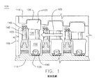
図面、特に図1を参照すると、回転部品105と静止部品110を有する蒸気タービン100の一部が示されている。回転部品105は、例えば、周方向に離隔した複数のバケット120がタービンの複数の軸方向位置に離隔して各タービン段の部分をなすように装着されたロータ115を含む。静止部品110は、ノズルを画成するパーティション130が取付けられた複数のダイアフラム125を含んでおり、それぞれのバケットと共に蒸気タービン100の様々な段を形成する。図1に示すように、ダイアフラム125の外側リング125は、バケット120の先端に隣接するシュラウド又はカバー145と共にシールするため、シール歯140の1以上の列を支持する。同様に、ダイアフラム125の内側リング150には、弧状シールセグメント155が取付けられる。シールセグメント155は、ロータ115と共にシールするため、半径方向内向きに延びる高低歯160を有する。同様のシールが、図示した通り蒸気タービン100の様々な段に設けられ、蒸気流路の方向は矢印165で示す。
With reference to the drawings, and in particular with reference to FIG. 1, a portion of a
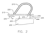
図2は、本発明の第1の実施形態に係る隙間閉鎖部品の概略断面図である。図2は、図3〜図12と同様に本発明の各種隙間閉鎖の動作を説明するために必要な図1に示す蒸気タービンの回転部品と静止部品の一部しか示していない。特に、図2は、蒸気タービンの回転部品用のシール歯205をもつバケット先端及びカバー200と、蒸気タービンの静止部品用のダイアフラム外側リング210を示す。ダイアフラム210には、タービン段の高圧端部220をタービン段の低圧端部225に接続する通路215が形成されている。この実施形態では、通路215は、好ましくはダイアフラム210外側リング210に形成された流路であって、蒸気が高圧上流位置(PUP)から低圧下流位置(PDOWN)へと流れる際に蒸気流路230からの代替漏れ経路を与える。低圧端部225の圧力は、高圧端部220(又は蒸気流路230を図示した箇所)の圧力よりも低い。低圧端部225の圧力が低いのは、第1のシール歯205での圧力降下に起因する。隙間閉鎖部品(例えば、フラップシール235)を開/閉させるのは、この差つまり高圧端部220と低圧端部225との圧力差である。高圧端部220をさらに上流側(例えば、ノズル前段の前方)に配置すれば、圧力差をさらに大きくすることができることは当業者には自明であろう。このことが図3〜図10に示す実施形態にも同様に当てはまることも当業者には自明であろう。図2では、通路215をU字形として示したが、高圧端部220から低圧端部225に蒸気流路230を移動させるための他の形状の通路も利用できることは当業者には自明であろう。
FIG. 2 is a schematic cross-sectional view of the gap closing component according to the first embodiment of the present invention. FIG. 2 shows only a part of the rotating parts and stationary parts of the steam turbine shown in FIG. 1 necessary for explaining the operations of various gap closings of the present invention as in FIGS. In particular, FIG. 2 shows a bucket tip and cover 200 with
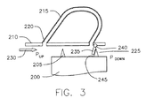
上述の通り、図2に示す実施形態の隙間閉鎖部品は、通路215の低圧端部225近傍のダイアフラム210外側リング210にヒンジ240でヒンジ接続されたフラップシール235を含む。図2に示すフラップシール235は休止又は非作動状態にある。つまり、高圧端部220と低圧端部225の間に圧力差は形成されていない。図3は、圧力差が形成されたときの作動状態のフラップシール235を示す。図3に示す作動状態では、フラップシール235は、通路215の低圧端部225から離れて、バケットカバー200のシール歯205を覆うように移動する。具体的には、フラップシール235は、蒸気漏れ経路の高圧領域に暴露されるシール歯205の面245を覆う。こうして、フラップシール235は、シール歯205と静止部品の外側静止部材の間に存在する隙間に蓋をすることができる。
As described above, the gap closure component of the embodiment shown in FIG. 2 includes a
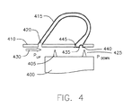
図4は、本発明の第2の実施形態に係る隙間閉鎖部品の概略断面図である。図4において、図2〜図3の部品と同様の部品には、図4で用いた符号には先頭に4を付した点を除いて、同じ符号を用いた。図4に示す実施形態の隙間閉鎖部品はフラップシール435であり、一端に溶接されたベロウ湾曲部440と、その反対側端部に垂直リップ445とを有する。この実施形態では、ベロウ湾曲部440は圧力差の存在下でシール歯405と結合し、垂直リップ445は圧力差の非存在下で通路415の低圧端部425と接触する。ベロウ湾曲部440はフラップシールのバネ定数及び圧力を下げ、一方、垂直リップ445は圧力を保ちフラップシールのはためきを防ぐのに役立つ。
FIG. 4 is a schematic cross-sectional view of a gap closing component according to the second embodiment of the present invention. In FIG. 4, the same reference numerals are used for parts similar to those in FIGS. 2 to 3 except that the reference numerals used in FIG. The gap closure component of the embodiment shown in FIG. 4 is a
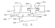
図5は、本発明の第3の実施形態に係る隙間閉鎖部品の概略断面図である。図5において、図2〜図3の部品と同様の部品には、図5で用いた符号には先頭に5を付した点を除いて、同じ符号を用いた。図5に示す実施形態の隙間閉鎖部品は、通路515の低圧端部525でダイアフラム210外側リング510の溝540に配置されたピストン535を含む。説明の便宜上、図5の通路515は、これまで図とは異なり、その全体は示していない点に留意されたい。この実施形態では、複数の湾曲バネ545が、各々、ピストン535の上側部分560の両端の上部セクション550と下部セクション555、並びにダイアフラム210外側リング510の溝540の一部と当接している。当業者には自明であろうが、この実施形態は、下側湾曲バネ545の設計が適切になされている限り、上側湾曲バネ545を使用しなくても実施できる。基本的に、上側湾曲バネ545の機能は、ピストン535を位置決めし、アセンブリががたつかないようにすることである。上側湾曲バネ545は、低い圧力差でシールを作動できるように荷重を調和させるのにも役立つ。下側湾曲バネ545は、圧力差の非存在下でピストン535を元の位置に戻すために用いられる。湾曲バネ545の第2の機能は、ピストン535周囲の隙間をシールすることである。
FIG. 5 is a schematic cross-sectional view of a gap closing component according to the third embodiment of the present invention. In FIG. 5, the same reference numerals are used for parts similar to those in FIGS. 2 to 3, except that the reference numerals used in FIG. The gap closure component of the embodiment shown in FIG. 5 includes a
図5に示すピストン535は休止又は非作動状態にある。つまり、通路515の高圧端部520と低圧端部525の間に圧力差は形成されていない。図6は、圧力差が形成されたときの作動状態のピストン535を示す。図6に示す作動状態では、圧力差の存在によって複数の湾曲バネ545の荷重バランスが崩れ、ピストン535を、バケットカバー500のシール歯505とダイアフラム外側リング510を通る蒸気流路530に向けて付勢する。
The
別の実施形態では、湾曲バネ545を1個だけ使用することもできる。さらに、別の実施形態では、隙間閉鎖部品で湾曲バネを一切使用しないようにすることもできる。この実施形態では、タービンの下半分のピストンは重力でその初期位置に戻るので、それらに戻り機構は必要とされない。
In another embodiment, only one
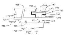
図7は、本発明の第4の実施形態に係る隙間閉鎖部品の概略断面図である。図7において、図5〜図6の部品と同様の部品には、図7で用いた符号には先頭に7を付した点を除いて、同じ符号を用いた。図7の実施形態では、2枚の二面バネ775を用いて、ピストン735の上部セクション780、側部セクション785、及び下部セクション790、並びにダイアフラム210外側リング710の溝740の一部分を当接させる。2枚の二面バネ775は側部セクション785にクリップ留めされる。この構成では、図5〜図6に示す実施形態に比べて部品の数が減り、バネの位置ずれの可能性が低減する。
FIG. 7 is a schematic cross-sectional view of a gap closing component according to the fourth embodiment of the present invention. In FIG. 7, the same reference numerals are used for parts similar to those in FIGS. 5 to 6 except that the reference numerals used in FIG. In the embodiment of FIG. 7, two
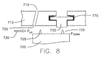
図7に示すピストン735は休止又は非作動状態にある。つまり、通路715の高圧端部720と低圧端部725の間に圧力差は形成されていない。図8は、圧力差が形成されたときの作動状態のピストン735を示す。図8に示す作動状態では、圧力差の存在によって二面バネ775の荷重バランスが崩れ、ピストン735を、蒸気流路530からバケットカバー700のシール歯705及びダイアフラム外側リング710を通って生じる蒸気漏れ経路に向けて付勢する。図5〜図6に示す実施形態と同様に、1枚の二面バネ775だけを使用することもできるし、或いはバネを使用しなくてもよい。
The
図9は、本発明の第5の実施形態に係る隙間閉鎖部品の概略断面図である。図9において、図5〜図6の部品と同様の部品には、図9で用いた符号には先頭に9を付した点を除いて、同じ符号を用いた。図9の実施形態では、エラストマー要素975を用いて、ピストン935の上側部分960の下部セクション980とダイアフラム外側リング910の溝940の一部分とを当接させる。当業者には自明であろうが、エラストマー要素975は様々な形状のものから構成でき、中実でも中空であってもよい。この実施形態において蒸気タービンの低温段に使用することのできるエラストマー要素の非限定的な例としては、VITON(400°F;DuPont Dow Elastomers社の登録商標である)、及びSILASTIC(600°F;Dow Corning Corporationの登録商標である)が挙げられる。
FIG. 9 is a schematic cross-sectional view of a gap closing component according to the fifth embodiment of the present invention. In FIG. 9, the same reference numerals are used for parts similar to those in FIGS. 5 to 6 except that the reference numerals used in FIG. In the embodiment of FIG. 9, an
図9に示すピストン935は休止又は非作動状態にある。つまり、通路915の高圧端部920と低圧端部925の間に圧力差は形成されていない。図10は、圧力差が形成されたときの作動状態のピストン935を示す。図10に示す作動状態では、圧力差の存在によってエラストマー要素975の荷重バランスが崩れ、ピストン935を、バケットカバー900のシール歯905及びダイアフラム外側リング910を通る蒸気流路から生じる蒸気漏れ経路に向けて付勢する。
The
別の実施形態では、エラストマー要素975を1個だけ使用することもできる。さらに、別の実施形態では、隙間閉鎖部品でエラストマー要素を一切使用しないようにすることもできる。この実施形態では、タービンの下半分のピストンは重力でその初期位置に戻るので、それらに戻り機構は必要とされない。
In another embodiment, only one
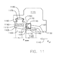
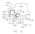
図11〜図12は、本発明の第6の実施形態に係る隙間閉鎖具の概略断面図である。図11〜図12は、蒸気タービンの簡略化された図を示している点では図3〜図10と同様であるが、図11〜図12では、蒸気タービンの回転部品及び静止部品を幾分詳細に示している。具体的には、図11〜図12は、回転部品用のシール歯1110をもつ先端カバー1105を有するバケット1100と、静止部品用のダイアフラム外側リング1115及び取付パーティション1120を示す。ダイアフラム外側リング1115には、タービン段の高圧端部1130をタービン段の低圧端部1135に接続する通路1125が形成されている。この実施形態では、通路1125は、好ましくは、ダイアフラム外側リング1115に形成された流路であって、蒸気が高圧上流位置(PUP)から低圧下流位置(PDOWN)へと流れる際の蒸気流路1140の代替漏れ経路を与える。
11 to 12 are schematic cross-sectional views of a gap closing device according to a sixth embodiment of the present invention. FIGS. 11-12 are similar to FIGS. 3-10 in that they show simplified views of the steam turbine, but in FIGS. 11-12, some of the rotating and stationary components of the steam turbine are somewhat It shows in detail. Specifically, FIGS. 11-12 show a
図11〜図12に示す実施形態の隙間閉鎖部品は、軸方向に作動する通路1125の低圧端部1135でダイアフラム外側リング1115の溝1150に配置されたピストン1145を含む。ピストン1145は、頂部1155と底部1160を含む。頂部1155の体積は底部1160よりも大きい。さらに、底部1160は、外向きに突き出た1以上のシール歯1165を有する。当業者には自明であろうが、この実施形態は、1つのシール歯しか有さないピストン1145でも、或いは所望によりシール歯のないピストン1145でも実施できる。ピストン1145の底部1160から外向きに突き出た1以上のシール歯1165は、図12に示す圧力差の存在下で、バケットカバー1105の1以上のシール歯1110及びダイアフラム外側リング1115を通る蒸気漏れ経路に向けて付勢される。具体的には、1本のシール歯1105がバケットから軸方向に突き出ている。ピストン1145によってもたらされるピストン作動シールは、バケットから突き出た軸方向歯1110と重なり合って、さらに流れを阻止し、漏出流に蛇行経路を生じる。図11〜図12は、この実施形態の隙間閉鎖部品が少なくとも2枚のバネ要素1170をさらに含んでいることを示している。各バネ要素1170は、ピストン1145の頂部及び底部並びにダイアフラム外側リング1115の溝1150の一部に当接する。図11〜図12は、2枚のバネ要素の使用について開示しているが、バネ要素を1枚だけ用いてもよいし、バネ要素を用いなくてもよいし、同様の機能をもつデバイス(エラストマー要素)を用いてもよい。図12に示すように、圧力差の存在によって2枚のバネ要素1170の荷重バランスが崩れ、ピストン1145の底部から外側に突き出した1以上のシール歯1165を、バケットカバー1105の1以上のシール歯1110及びダイアフラム外側リング1115を通る蒸気漏れ経路に向けて付勢する。当業者には自明であろうが、この実施形態のシールは1枚のバネ要素1170だけで作動することができ、この実施形態は、図11〜図12に示すバネの数に限定されない。
The gap closure component of the embodiment shown in FIGS. 11-12 includes a
図11〜図12の実施形態に示す追加の要素として、ダイアフラム外側リング1115の延長部1190の溝1185に配置された1以上のシール歯1180を有するシール支持体1175がある。シール支持体1175は、バケットカバー1105の1以上のシール歯1110に対して半径方向にある。シール支持体1175は、蒸気タービンの回転部品と静止部品を流れるシール経路のシールを与える役割も果たす。
An additional element shown in the embodiment of FIGS. 11-12 is a
特に好ましい実施形態に関して説明してきたが、様々な変形及び修正は当業者には明らかであろう。従って、特許請求の範囲は、本発明の技術的範囲に属する修正及び変更を包含する。 While described with respect to particularly preferred embodiments, various variations and modifications will be apparent to those skilled in the art. Accordingly, the appended claims encompass modifications and variations that fall within the scope of the present invention.
100 蒸気タービン
105 回転部品
110 静止部品
115 ロータ
120 バケット
125 複数のダイアフラム
130 取付パーティション
135 外側リング
140 シール歯
145 シュラウド又はカバー
150 内側リング
155 弧状シールセグメント
160 高−低歯
165 蒸気流路
200 バケット先端及びカバー
205 シール歯
210 ダイアグラム外側リング
215 通路
220 高圧端部
225 低圧端部
230 蒸気流路
235 フラップシール
240 ヒンジ
245 シール歯の面
400 バケット先端及びカバー
405 シール歯
410 ダイアグラム外側リング
415 通路
420 高圧端部
425 低圧端部
430 蒸気流路
435 フラップシール
440 ベロウ湾曲部
445 垂直先端部
500 バケットカバー
505 シール歯
510 ダイアグラム 外側リング
515 通路
520 高圧端部
525 低圧端部
530 蒸気流路
535 ピストン
540 溝
545 複数の湾曲バネ
550 上部セクション
555 下部セクション
560 上側部分
700 バケットカバー
705 シール歯
710 ダイアグラム外側リング
715 通路
720 高圧端部
725 低圧端部
730 蒸気流路
735 ピストン
740 溝
760 上側部分
775 2枚の二面バネ
780 上部セクション
785 側部セクション
790 下部セクション
900 バケットカバー
905 シール歯
910 ダイアグラム外側リング
915 通路
920 高圧端部
925 低圧端部
935 ピストン
940 溝
960 上側部分
975 エラストマー要素
980 下部セクション
1100 バケット
1105 先端カバー
1110 シール歯
1115 ダイアグラム外側リング
1120 取付パーティション
1125 通路
1130 高圧端部
1135 低圧端部
1145 ピストン
1150 溝
1155 頂部
1160 底部
1165 シール歯
1170 バネ要素
1175 シール支持体
1180 シール歯
1185 溝
1190 延長部
100 Steam turbine 105 Rotating part 110 Stationary part 115 Rotor 120 Bucket 125 Multiple diaphragms 130 Mounting partition 135 Outer ring 140 Seal teeth 145 Shroud or cover 150 Inner ring 155 Arc-shaped seal segment 160 High-low teeth 165 Steam channel 200 Bucket tip and Cover 205 Seal tooth 210 Diagram outer ring 215 Passage 220 High pressure end 225 Low pressure end 230 Steam flow path 235 Flap seal 240 Hinge 245 Seal tooth face 400 Bucket tip and cover 405 Seal tooth 410 Diagram outer ring 415 Passage 420 High pressure end 425 Low pressure end 430 Steam flow path 435 Flap seal 440 Bellow curved portion 445 Vertical tip 500 Bucket cover 505 Seal teeth 510 Diag Ram outer ring 515 passage 520 high pressure end 525 low pressure end 530 steam passage 535 piston 540 groove 545 multiple curved springs 550 upper section 555 lower section 560 upper portion 700 bucket cover 705 seal teeth 710 diagram outer ring 715 passage 720 high pressure end Portion 725 Low pressure end 730 Steam channel 735 Piston 740 Groove 760 Upper part 775 Two springs 780 Upper section 785 Side section 790 Lower section 900 Bucket cover 905 Seal teeth 910 Diagram outer ring 915 Passage 920 High pressure end 925 Low pressure end 935 Piston 940 Groove 960 Upper portion 975 Elastomer element 980 Lower section 1100 Bucket 1105 Tip cover 1110 Seal teeth 1115 Diagram Outer ring 1120 Mounting partition 1125 Passage 1130 High pressure end 1135 Low pressure end 1145 Piston 1150 Groove 1155 Top 1160 Bottom 1165 Seal teeth 1170 Spring element 1175 Seal support 1180 Seal teeth 1185 Groove 1190 Extension
Claims (10)
複数の軸方向位置に離隔しかつ周方向に離隔した複数のバケットを含む回転部品(105)であって、複数のバケットの各々が、1以上のシール歯を含む隣接カバーを備える先端を有する回転部品(105)と、
取付パーティションで隔てられたダイアフラム外側リングと内側ダイアフラムリングを各々有する複数のダイアフラムを含む静止部品(110)であって、複数のダイアフラムが軸方向に複数のバケットの隣り合った列の間に配置されていて、各列がタービン(100)を通る蒸気流路の一部を画成するタービン段を形成し、各ダイアフラム外側リングに高圧端部を低圧端部と接続する通路が形成されている、静止部品(110)と、
蒸気漏れ経路の一部をシールするため回転部品(105)及び静止部品(110)の周辺に配置された隙間閉鎖部品であって、隙間閉鎖部品が複数の隙間閉鎖具を含んでおり、複数の隙間閉鎖具の各々が、それぞれのダイアグラム外側リング及びバケットカバーの1以上のシール歯の周辺に配置されていて、複数の隙間閉鎖具の各々が、それぞれのダイアフラム外側リングの通路で形成される圧力差によって作動され、バケットカバーの1以上のシール歯とダイアフラム外側リングを通る蒸気漏れ経路をシールする隙間閉鎖部品と
を備える蒸気タービン(100)。 A steam turbine (100),
Rotating component (105) comprising a plurality of buckets spaced apart in a plurality of axial positions and circumferentially spaced, each having a tip with an adjacent cover comprising one or more seal teeth Parts (105);
A stationary component (110) comprising a plurality of diaphragms each having a diaphragm outer ring and an inner diaphragm ring separated by a mounting partition, the plurality of diaphragms being disposed between adjacent rows of a plurality of buckets in an axial direction. Each row forms a turbine stage that defines a portion of the steam flow path through the turbine (100), and each diaphragm outer ring is formed with a passage connecting the high pressure end to the low pressure end, A stationary component (110);
A gap closing part disposed around the rotating part (105) and the stationary part (110) for sealing a part of the steam leakage path, wherein the gap closing part includes a plurality of gap closing devices, Each of the gap closures is disposed around one or more seal teeth of the respective diagram outer ring and bucket cover, and each of the plurality of gap closures is formed by a passage in the respective diaphragm outer ring A steam turbine (100) actuated by the difference and comprising one or more seal teeth of the bucket cover and a gap closure component that seals a steam leakage path through the diaphragm outer ring.
Applications Claiming Priority (1)
| Application Number | Priority Date | Filing Date | Title |
|---|---|---|---|
| US12/260,573 US8021103B2 (en) | 2008-10-29 | 2008-10-29 | Pressure activated flow path seal for a steam turbine |
Publications (1)
| Publication Number | Publication Date |
|---|---|
| JP2010106830A true JP2010106830A (en) | 2010-05-13 |
Family
ID=41419510
Family Applications (1)
| Application Number | Title | Priority Date | Filing Date |
|---|---|---|---|
| JP2009241947A Withdrawn JP2010106830A (en) | 2008-10-29 | 2009-10-21 | Pressure activated flow path seal for steam turbine |
Country Status (4)
| Country | Link |
|---|---|
| US (1) | US8021103B2 (en) |
| EP (1) | EP2182174A3 (en) |
| JP (1) | JP2010106830A (en) |
| RU (1) | RU2478799C2 (en) |
Cited By (2)
| Publication number | Priority date | Publication date | Assignee | Title |
|---|---|---|---|---|
| JP2012145060A (en) * | 2011-01-14 | 2012-08-02 | Hitachi Ltd | Sealing structure for steam turbine |
| JP2020505555A (en) * | 2017-02-02 | 2020-02-20 | ゼネラル・エレクトリック・カンパニイ | Turbine tip balance slit |
Families Citing this family (11)
| Publication number | Priority date | Publication date | Assignee | Title |
|---|---|---|---|---|
| US8052380B2 (en) * | 2008-10-29 | 2011-11-08 | General Electric Company | Thermally-activated clearance reduction for a steam turbine |
| US8021103B2 (en) | 2008-10-29 | 2011-09-20 | General Electric Company | Pressure activated flow path seal for a steam turbine |
| US8864443B2 (en) * | 2010-07-14 | 2014-10-21 | Hitachi, Ltd. | Sealing device for steam turbines and method for controlling sealing device |
| EP2597265A1 (en) * | 2011-11-28 | 2013-05-29 | Siemens Aktiengesellschaft | Rotor blade for an axial throughflow turbo engine |
| PL225446B1 (en) | 2013-04-30 | 2017-04-28 | Gen Electric | Thermal space management system in a turbine |
| ITFI20130237A1 (en) * | 2013-10-14 | 2015-04-15 | Nuovo Pignone Srl | "SEALING CLEARANCE CONTROL IN TURBOMACHINES" |
| US9829007B2 (en) | 2014-05-23 | 2017-11-28 | General Electric Company | Turbine sealing system |
| FR3027622B1 (en) | 2014-10-28 | 2018-11-09 | Safran Aircraft Engines | ACTIVE ROTOR ROTOR DRAW, ROTATING ASSEMBLY AND METHOD OF OPERATING THE SAME |
| US10370994B2 (en) | 2015-05-28 | 2019-08-06 | Rolls-Royce North American Technologies Inc. | Pressure activated seals for a gas turbine engine |
| US10653307B2 (en) * | 2018-10-10 | 2020-05-19 | Wm & Dg, Inc. | Medical devices for airway management and methods of placement |
| RU196211U1 (en) * | 2019-12-04 | 2020-02-19 | Федеральное государственное бюджетное образовательное учреждение высшего образования «Брянский государственный технический университет» | Seal of the radial clearance of the turbomachine guideless apparatus |
Family Cites Families (15)
| Publication number | Priority date | Publication date | Assignee | Title |
|---|---|---|---|---|
| NL269161A (en) * | 1960-09-28 | |||
| JPS57122103A (en) * | 1981-01-21 | 1982-07-29 | Hitachi Ltd | Seal device at moving blade end |
| US5601402A (en) * | 1986-06-06 | 1997-02-11 | The United States Of America As Represented By The Secretary Of The Air Force | Turbo machine shroud-to-rotor blade dynamic clearance control |
| SU1687804A1 (en) * | 1989-06-09 | 1991-10-30 | Военно-воздушная инженерная Краснознаменная академия им.проф.Н.Е.Жуковского | Device for regulating axial clearances in blade machines of gas-turbine engines |
| US5098257A (en) | 1990-09-10 | 1992-03-24 | Westinghouse Electric Corp. | Apparatus and method for minimizing differential thermal expansion of gas turbine vane structures |
| US5234318A (en) | 1993-01-22 | 1993-08-10 | Brandon Ronald E | Clip-on radial tip seals for steam and gas turbines |
| US5333993A (en) | 1993-03-01 | 1994-08-02 | General Electric Company | Stator seal assembly providing improved clearance control |
| DE19938274A1 (en) | 1999-08-12 | 2001-02-15 | Asea Brown Boveri | Device and method for drawing the gap between the stator and rotor arrangement of a turbomachine |
| JP4301692B2 (en) | 2000-03-31 | 2009-07-22 | 三菱重工業株式会社 | gas turbine |
| RU2211975C1 (en) * | 2002-01-31 | 2003-09-10 | Общество с ограниченной ответственностью "Энергосервис" | Device for sealing of steam turbine stage clearance |
| US6926495B2 (en) | 2003-09-12 | 2005-08-09 | Siemens Westinghouse Power Corporation | Turbine blade tip clearance control device |
| US7287956B2 (en) * | 2004-12-22 | 2007-10-30 | General Electric Company | Removable abradable seal carriers for sealing between rotary and stationary turbine components |
| US8540479B2 (en) * | 2007-01-11 | 2013-09-24 | General Electric Company | Active retractable seal for turbo machinery and related method |
| US8021103B2 (en) | 2008-10-29 | 2011-09-20 | General Electric Company | Pressure activated flow path seal for a steam turbine |
| US8052380B2 (en) * | 2008-10-29 | 2011-11-08 | General Electric Company | Thermally-activated clearance reduction for a steam turbine |
-
2008
- 2008-10-29 US US12/260,573 patent/US8021103B2/en not_active Expired - Fee Related
-
2009
- 2009-10-21 JP JP2009241947A patent/JP2010106830A/en not_active Withdrawn
- 2009-10-23 EP EP09173962A patent/EP2182174A3/en not_active Withdrawn
- 2009-10-28 RU RU2009139894/06A patent/RU2478799C2/en not_active IP Right Cessation
Cited By (3)
| Publication number | Priority date | Publication date | Assignee | Title |
|---|---|---|---|---|
| JP2012145060A (en) * | 2011-01-14 | 2012-08-02 | Hitachi Ltd | Sealing structure for steam turbine |
| JP2020505555A (en) * | 2017-02-02 | 2020-02-20 | ゼネラル・エレクトリック・カンパニイ | Turbine tip balance slit |
| JP7187464B2 (en) | 2017-02-02 | 2022-12-12 | ゼネラル・エレクトリック・カンパニイ | Turbine tip balance slit |
Also Published As
| Publication number | Publication date |
|---|---|
| US8021103B2 (en) | 2011-09-20 |
| US20100104427A1 (en) | 2010-04-29 |
| EP2182174A3 (en) | 2012-03-14 |
| EP2182174A2 (en) | 2010-05-05 |
| RU2009139894A (en) | 2011-05-10 |
| RU2478799C2 (en) | 2013-04-10 |
Similar Documents
| Publication | Publication Date | Title |
|---|---|---|
| JP2010106830A (en) | Pressure activated flow path seal for steam turbine | |
| US8052380B2 (en) | Thermally-activated clearance reduction for a steam turbine | |
| JP5830247B2 (en) | Method and apparatus for labyrinth seal packing ring | |
| US8317464B2 (en) | Reverse flow tolerant spring activated brush seal | |
| US8573603B2 (en) | Split ring seal with spring element | |
| US10202863B2 (en) | Seal ring for gas turbine engines | |
| JP5329248B2 (en) | Retractable elastic plate seal | |
| US9394799B1 (en) | Air riding seal for a turbine | |
| CN101096998B (en) | Variable clearance packing ring and promoting method | |
| JP4130581B2 (en) | Auxiliary seal for string hinge seal in gas turbine | |
| CN108533334B (en) | Turbine suction face seal assemblies | |
| JP2015522745A (en) | Seal between stationary parts of turbine | |
| JP2009197633A (en) | Turbo charger | |
| JP6640517B2 (en) | Sealing segment | |
| US9347333B2 (en) | Brush ring seal | |
| JP2019039386A (en) | gas turbine | |
| KR20030057409A (en) | Composite tubular woven seal for gas turbine nozzle and shroud interface | |
| JP4248870B2 (en) | Auxiliary seal for string hinge seal in gas turbine | |
| US20050194747A1 (en) | Sealing arrangement | |
| JP2008045550A (en) | Variable gap packing ring segment | |
| US20220307603A1 (en) | Non-contact seal assembly with damping elements | |
| JP2002266605A (en) | Non-retractable segmented packing ring for fluid turbine having special spring for reducing force between shaft friction | |
| CN101113677A (en) | Suction labyrinth seals | |
| CN112840105B (en) | Sealing of a turbine | |
| CN115680897A (en) | Turbine engine with floating seal assembly |
Legal Events
| Date | Code | Title | Description |
|---|---|---|---|
| A621 | Written request for application examination |
Free format text: JAPANESE INTERMEDIATE CODE: A621 Effective date: 20121012 |
|
| A761 | Written withdrawal of application |
Free format text: JAPANESE INTERMEDIATE CODE: A761 Effective date: 20130705 |