EP2182175A2 - Gehäusestruktur und Verfahren zur Verbesserung des thermischen Verhaltens der Turbine während transienter und stationärer Betriebsbedingungen - Google Patents
Gehäusestruktur und Verfahren zur Verbesserung des thermischen Verhaltens der Turbine während transienter und stationärer Betriebsbedingungen Download PDFInfo
- Publication number
- EP2182175A2 EP2182175A2 EP09173963A EP09173963A EP2182175A2 EP 2182175 A2 EP2182175 A2 EP 2182175A2 EP 09173963 A EP09173963 A EP 09173963A EP 09173963 A EP09173963 A EP 09173963A EP 2182175 A2 EP2182175 A2 EP 2182175A2
- Authority
- EP
- European Patent Office
- Prior art keywords
- casing
- flanges
- bosses
- horizontal
- turbine
- Prior art date
- Legal status (The legal status is an assumption and is not a legal conclusion. Google has not performed a legal analysis and makes no representation as to the accuracy of the status listed.)
- Granted
Links
Images

Classifications
-
- F—MECHANICAL ENGINEERING; LIGHTING; HEATING; WEAPONS; BLASTING
- F01—MACHINES OR ENGINES IN GENERAL; ENGINE PLANTS IN GENERAL; STEAM ENGINES
- F01D—NON-POSITIVE DISPLACEMENT MACHINES OR ENGINES, e.g. STEAM TURBINES
- F01D11/00—Preventing or minimising internal leakage of working-fluid, e.g. between stages
- F01D11/08—Preventing or minimising internal leakage of working-fluid, e.g. between stages for sealing space between rotor blade tips and stator
- F01D11/14—Adjusting or regulating tip-clearance, i.e. distance between rotor-blade tips and stator casing
- F01D11/20—Actively adjusting tip-clearance
- F01D11/24—Actively adjusting tip-clearance by selectively cooling-heating stator or rotor components
-
- F—MECHANICAL ENGINEERING; LIGHTING; HEATING; WEAPONS; BLASTING
- F01—MACHINES OR ENGINES IN GENERAL; ENGINE PLANTS IN GENERAL; STEAM ENGINES
- F01D—NON-POSITIVE DISPLACEMENT MACHINES OR ENGINES, e.g. STEAM TURBINES
- F01D25/00—Component parts, details, or accessories, not provided for in, or of interest apart from, other groups
- F01D25/08—Cooling; Heating; Heat-insulation
- F01D25/14—Casings modified therefor
-
- F—MECHANICAL ENGINEERING; LIGHTING; HEATING; WEAPONS; BLASTING
- F01—MACHINES OR ENGINES IN GENERAL; ENGINE PLANTS IN GENERAL; STEAM ENGINES
- F01D—NON-POSITIVE DISPLACEMENT MACHINES OR ENGINES, e.g. STEAM TURBINES
- F01D25/00—Component parts, details, or accessories, not provided for in, or of interest apart from, other groups
- F01D25/24—Casings; Casing parts, e.g. diaphragms, casing fastenings
- F01D25/26—Double casings; Measures against temperature strain in casings
-
- F—MECHANICAL ENGINEERING; LIGHTING; HEATING; WEAPONS; BLASTING
- F05—INDEXING SCHEMES RELATING TO ENGINES OR PUMPS IN VARIOUS SUBCLASSES OF CLASSES F01-F04
- F05D—INDEXING SCHEME FOR ASPECTS RELATING TO NON-POSITIVE-DISPLACEMENT MACHINES OR ENGINES, GAS-TURBINES OR JET-PROPULSION PLANTS
- F05D2230/00—Manufacture
- F05D2230/60—Assembly methods
- F05D2230/64—Assembly methods using positioning or alignment devices for aligning or centring, e.g. pins
- F05D2230/642—Assembly methods using positioning or alignment devices for aligning or centring, e.g. pins using maintaining alignment while permitting differential dilatation
-
- F—MECHANICAL ENGINEERING; LIGHTING; HEATING; WEAPONS; BLASTING
- F05—INDEXING SCHEMES RELATING TO ENGINES OR PUMPS IN VARIOUS SUBCLASSES OF CLASSES F01-F04
- F05D—INDEXING SCHEME FOR ASPECTS RELATING TO NON-POSITIVE-DISPLACEMENT MACHINES OR ENGINES, GAS-TURBINES OR JET-PROPULSION PLANTS
- F05D2240/00—Components
- F05D2240/10—Stators
- F05D2240/14—Casings or housings protecting or supporting assemblies within
Definitions
- the present invention relates to gas turbines, and more particularly, to a structure for and method of improving a turbine's thermal response during transient and steady state operating conditions.
- Turbine stator casings are typically comprised of a semi-cylindrical upper half and a semi-cylindrical lower half that are joined together at horizontal split-line joints that can have an effect on a casing's roundness. Attempts have been made to reduce the out-of-roundness effects associated with the use of horizontal joints by adding false flanges, which add mass at discrete locations, such as at the vertical plane of the casing. However, the added mass from the use of false flanges typically causes a thermal "lag" during the transient response of the machine.
- a turbine casing with increased heat transfer at locations with increased mass comprises an upper casing half with first and second upper flanges, a lower casing half with first and second lower flanges, the upper flanges being joined to corresponding lower flanges to thereby join the upper and lower casing halves to one another to form the casing, the joined flanges being positioned substantially at the horizontal symmetry plane of the casing, a first false flange positioned on the upper casing half substantially at the vertical symmetry plane of the casing, a second false flange positioned on the lower casing half substantially at the vertical symmetry plane of the casing, a plenum located within and extending circumferentially around the turbine casing within which a cooling fluid flows circumferentially around the turbine casing, and a plurality of bosses positioned around the circumference of the casing for introducing the cooling fluid into the plenum at a plurality of locations around the circumference of the casing so that the cooling fluid has first
- a turbine casing with increased heat transfer at locations with increased mass comprises a semi-cylindrical upper casing half with first and second upper flanges extending generally radially from opposite ends of the upper casing half, a semi-cylindrical lower casing half with first and second lower flanges extending generally radially from opposite ends of the lower casing half, the upper flanges being joined to corresponding lower flanges to thereby join the upper and lower casing halves to one another to form the casing, the joined flanges being positioned substantially at the horizontal symmetry plane of the casing, a plurality of flanges extending generally radially from the upper and lower casing halves, a first of the plurality of flanges being sized and/or dimensioned to substantially match the stiffness and the thermal mass of each of the joined upper and lower flanges together, and being positioned on the upper casing half substantially at the vertical symmetry plane of the casing, a second of the
- a method of increasing heat transfer at turbine casing locations with increased mass comprises the steps of providing an upper casing half with first and second upper flanges, providing a lower casing half with first and second lower flanges, joining the upper flanges to corresponding lower flanges to thereby join the upper and lower casing halves to one another to form the casing, and thereby position the joined flanges substantially at the horizontal symmetry plane of the casing, providing a first false flange on the upper casing half substantially at the vertical symmetry plane of the casing, providing a second false flange on the lower casing half substantially at the vertical symmetry plane of the casing, providing a plenum within and extending circumferentially around the turbine casing, causing a cooling fluid to flow circumferentially around the turbine casing, and positioning a plurality of bosses around the circumference of the casing to introduce the cooling fluid into the plenum at a plurality of locations around the circumference of the casing so
- Prior art solutions to reduced cooling flow have used symmetrical placement of bosses and/or cooling flows, whereas the present invention uses asymmetrical placement of cooling flows (that can be asymmetrical in placement relative to the specific planes or in mass flow rates within a plenum) to increase heat transfer at desired locations.
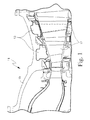
- Figure 1 is a partial cross-sectional view of a conventional gas turbine 11 showing a plenum 13 in the turbine's outer stator casing 15 for supplying cooling fluid to static vanes or nozzles (not shown) attached to the turbine's outer flow path wall.
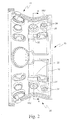
- FIG. 2 is a top view of a gas turbine shell or casing 10, while Figure 3 is a cross-sectional view of the gas turbine casing 10 taken along the line A-A in Figure 2 .
- casing 10 is generally cylindrical in shape.
- Casing 10 is comprised of a semi-cylindrical upper half 12 and a semi-cylindrical lower half 14 that are joined together at horizontal split-line joints 16.
- Each of horizontal split-line joints 16 is formed from a pair of upper and lower flanges 18U and 18L.
- Upper flanges 18U extend generally radially from diametrically opposite ends of upper casing half 12.
- Lower flanges 18L extend generally radially from diametrically opposite ends of lower casing half 14.
- Flanges 18U and 18L also extend generally horizontally along diametrically opposed sides of the cylindrical halves 12 and 14.
- flanges 18U are bolted to corresponding flanges 18L, to thereby join the casing halves 12 and 14 to one another to form turbine casing 10, although it should be noted that other methods of joining such flanges together, other than bolting, could be used.
- each of flanges 22 is spaced diametrically opposite another flange 22 on casing 10.
- Each of flanges 22 extends generally radially from and horizontally along the sides of casing halves 12 and 14.
- Two of the "false" flanges 22U and 22L are each spaced approximately 90° circumferentially from the horizontal split-line joints 16 and diametrically opposite one another on casing 10.
- false flanges 22U and 22L are each sized and/or dimensioned to substantially match the stiffness and the thermal mass of one of the split-line joints 16.
- the turbine section of a gas turbine typically has static vanes or nozzles (not shown) attached to the outer flow path wall of the turbine casing.
- One means of allowing the nozzles to operate at high temperatures is to provide cooling fluid, such as air, to the nozzles.
- the cooling fluid is provided to the individual nozzles by pipes (not shown) attached to the outer wall of casing 10 through bosses 24 located at discrete locations around the circumference of casing 10.
- the cooling fluid passes through the pipes, bosses 24 and the outer wall 26 of casing 10, and into a plenum 28 located within casing 10, but outboard of the nozzles.
- the cooling fluid 25 then travels circumferentially around the turbine casing 10 in plenum 28 to access the individual nozzles.
- the bosses 24 where the cooling fluid pipes are attached to casing 10 are typically positioned symmetrically relative to the machine's horizontal symmetry plane 31 and/or vertical symmetry plane 33.
- One adverse effect from this symmetrical positioning of the cooling fluid pipes and bosses 24 is that the cooling supply symmetry planes 30 and 32 are coincident with the geometric symmetry planes 31 and 33 of casing 10, which results in reduced cooling flow at locations 27 and 29 shown in Figure 3 . Locations 27 and 29 correspond to split-line joints 16 and false flanges 22U and 22L.
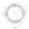
- Figure 4 is a cross-sectional view of the gas turbine casing 10 shown in Figures 2 and 3 , again taken along the line A-A in Figure 2 , but modified to show the re-positioning of bosses 24 to the locations of bosses 24' to improve cooling fluid flow in locations 27 and 29.
- the cross-sectional view of turbine casing 10 shown in Figure 4 is an exemplary embodiment of the structure and method of the present invention for controlling distortion in a turbine casing 10, by moving the cooling supply ports, such as bosses 24 through which the cooling fluid pipes are attached to the outer wall 28 of casing 10.
- the cooling supply symmetry planes 30 and 32 are shifted so that shifted cooling supply symmetry planes 30' and 32' are not coincident with the geometric symmetry planes 31 and 33 of casing 10. This allows for better convective heat transfer at the locations 27 of joints 16 and 29 of false flanges 22U and 22L, where there is increased mass. This shift in cooling supply symmetry planes 30' and 32' has a positive impact on the transient and steady state clearances of casing 10.
- the problem of reduced cooling flow is solved by repositioning the cooling supply ports fed by bosses 24', so that the cooling supply symmetry planes 30' and 32' are not coincident with the geometric symmetry planes 31 and 33.
- This allows for better convective heat transfer at locations 27 and 29 where there is increased mass due to joints 16 and false flanges 22U and 22L being located there.
- This in effect, has a positive impact on the transient and steady state clearances of the machine.
- the present invention uses asymmetrical placement of the cooling ports (bosses 24) on the turbine casing 10 to increase the flow (and associated heat transfer) at the horizontal joint and false flange locations 27 and 29.
- the placement of bosses 24' can be optimized to increase the heat transfer at the axis-symmetric regions, while increasing it at the asymmetric regions 27 and 29.
- bosses 24' shown in Figure 4 are repositioned bosses 24, moved to coincide with the desired entry point of the cooling flow 25'.
- the range in degrees by which the 24' can be shifted away from the positions of bosses 24 that coincide with axis-symmetric placement depends on the actual number of entry points.
- the bosses 24'/cooling flows 25' can be re-positioned until interference with the horizontal joint 16 becomes an issue ( i . e ., at approximately 35 degrees).
- bosses 24 there are four bosses 24, as shown in Figure 3 , then repositioning the bosses 24 45° or 135° puts a boss 24' right on the horizontal joint 16, which is an undesirable configuration. However, if there are twice as many entry points, then the angle of rotation of bosses 24' would be much smaller before interference with the horizontal joint 16 occurred. As the bosses 24' are repositioned from the location shown in Figure 3 towards the horizontal plane 31, the impact of the cooling flow 25' on the horizontal joints 16 increases. There is no set “best case”. The result of repositioning bosses 24' is configuration specific, depending on the relative difference in thickness between the horizontal joint 16 and the casing wall 10, and the mass flow rate of the cooling air 25'.
- the significant feature of the present invention is that the positioning of the bosses 24 is such that the cooling flow 25 provided by them is tunable, whereby the bosses 24 can be repositioned as bosses 24' to achieve cooling flow 25' past the horizontal joints 16 and false flanges 22U and 22L in the embodiment of Figure 4 , whereas in the original configuration of Figure 3 there is no cooling flow past the horizontal joints 16.
- the cooling flow has a very different impact on the casing 10 at the horizontal joint location 16.
- the positions of the bosses 24 can be optimized to provide better heat transfer coefficients not only at the horizontal joints 16 and the false flanges 22U and 22L, but also at other locations, such as lifting lug reinforcement pads, etc . Also changing the positions of the bosses 24 does hot eliminate the possibility of using the same casting Part Number on the upper and lower halves of a casing 10 where false bosses are incorporated.
Landscapes
- Engineering & Computer Science (AREA)
- Mechanical Engineering (AREA)
- General Engineering & Computer Science (AREA)
- Turbine Rotor Nozzle Sealing (AREA)
Applications Claiming Priority (1)
| Application Number | Priority Date | Filing Date | Title |
|---|---|---|---|
| US12/289,567 US8047763B2 (en) | 2008-10-30 | 2008-10-30 | Asymmetrical gas turbine cooling port locations |
Publications (3)
| Publication Number | Publication Date |
|---|---|
| EP2182175A2 true EP2182175A2 (de) | 2010-05-05 |
| EP2182175A3 EP2182175A3 (de) | 2013-10-09 |
| EP2182175B1 EP2182175B1 (de) | 2018-10-03 |
Family
ID=41600544
Family Applications (1)
| Application Number | Title | Priority Date | Filing Date |
|---|---|---|---|
| EP09173963.1A Not-in-force EP2182175B1 (de) | 2008-10-30 | 2009-10-23 | Gehäusestruktur und Verfahren zur Verbesserung des thermischen Verhaltens der Turbine während transienter und stationärer Betriebsbedingungen |
Country Status (4)
| Country | Link |
|---|---|
| US (1) | US8047763B2 (de) |
| EP (1) | EP2182175B1 (de) |
| JP (1) | JP5378943B2 (de) |
| CN (1) | CN101725378B (de) |
Cited By (5)
| Publication number | Priority date | Publication date | Assignee | Title |
|---|---|---|---|---|
| EP2551472A1 (de) * | 2011-07-29 | 2013-01-30 | Siemens Aktiengesellschaft | Gehäuse für eine Strömungsmaschine |
| EP2636850A1 (de) * | 2012-03-09 | 2013-09-11 | General Electric Company | Stator einer Gasturbine |
| EP3023600A1 (de) | 2014-11-24 | 2016-05-25 | Alstom Technology Ltd | Motorgehäuseelement |
| US9897318B2 (en) | 2014-10-29 | 2018-02-20 | General Electric Company | Method for diverting flow around an obstruction in an internal cooling circuit |
| US10415477B2 (en) | 2013-07-31 | 2019-09-17 | General Electric Company | Turbine casing false flange flow diverter |
Families Citing this family (6)
| Publication number | Priority date | Publication date | Assignee | Title |
|---|---|---|---|---|
| DE102009017798A1 (de) * | 2009-04-20 | 2010-10-21 | Human Solutions Gmbh | Vorrichtung und Verfahren zur Produktoptimierung auf Basis nationaler und internationaler Reihenmessungsdaten |
| US9382810B2 (en) | 2012-07-27 | 2016-07-05 | General Electric Company | Closed loop cooling system for a gas turbine |
| US10030539B2 (en) * | 2012-12-18 | 2018-07-24 | United Technologies Corporation | Gas turbine engine inner case including non-symmetrical bleed slots |
| US8920109B2 (en) * | 2013-03-12 | 2014-12-30 | Siemens Aktiengesellschaft | Vane carrier thermal management arrangement and method for clearance control |
| US20180154626A1 (en) * | 2016-12-01 | 2018-06-07 | Arconic Inc. | Components with integral hardware and method of manufacturing same |
| US11169041B2 (en) * | 2018-03-21 | 2021-11-09 | Gaurav HIRLEKAR | Differential pressure indicating device |
Family Cites Families (18)
| Publication number | Priority date | Publication date | Assignee | Title |
|---|---|---|---|---|
| FR2540939A1 (fr) * | 1983-02-10 | 1984-08-17 | Snecma | Anneau d'etancheite pour un rotor de turbine d'une turbomachine et installation de turbomachine munie de tels anneaux |
| DE3424141A1 (de) * | 1984-06-30 | 1986-01-09 | BBC Aktiengesellschaft Brown, Boveri & Cie., Baden, Aargau | Luftspeicher-gasturbine |
| US5049033A (en) * | 1990-02-20 | 1991-09-17 | General Electric Company | Blade tip clearance control apparatus using cam-actuated shroud segment positioning mechanism |
| CA2039756A1 (en) * | 1990-05-31 | 1991-12-01 | Larry Wayne Plemmons | Stator having selectively applied thermal conductivity coating |
| US5281085A (en) * | 1990-12-21 | 1994-01-25 | General Electric Company | Clearance control system for separately expanding or contracting individual portions of an annular shroud |
| US5205115A (en) * | 1991-11-04 | 1993-04-27 | General Electric Company | Gas turbine engine case counterflow thermal control |
| US5605438A (en) * | 1995-12-29 | 1997-02-25 | General Electric Co. | Casing distortion control for rotating machinery |
| EP0952311A1 (de) * | 1998-04-06 | 1999-10-27 | Siemens Aktiengesellschaft | Strömungsmaschine mit einem Innengehäuse und einem Aussengehäuse |
| WO2000011324A1 (de) * | 1998-08-18 | 2000-03-02 | Siemens Aktiengesellschaft | Turbinengehäuse |
| JP4274666B2 (ja) * | 2000-03-07 | 2009-06-10 | 三菱重工業株式会社 | ガスタービン |
| JP2002309906A (ja) * | 2001-04-11 | 2002-10-23 | Mitsubishi Heavy Ind Ltd | 蒸気冷却型ガスタービン |
| US7048496B2 (en) * | 2002-10-31 | 2006-05-23 | General Electric Company | Turbine cooling, purge, and sealing system |
| FR2867805A1 (fr) * | 2004-03-18 | 2005-09-23 | Snecma Moteurs | Stator de turbine haute-pression de turbomachine et procede d'assemblage |
| GB0513654D0 (en) * | 2005-07-02 | 2005-08-10 | Rolls Royce Plc | Variable displacement turbine liner |
| CN1888398A (zh) * | 2006-07-19 | 2007-01-03 | 岑保卫 | 汽轮机汽缸外壳保温方法及保温仓 |
| CN100378296C (zh) * | 2006-07-19 | 2008-04-02 | 上海汽轮机有限公司 | 一种汽轮机高压内缸冷却方法 |
| JP4279857B2 (ja) * | 2006-07-20 | 2009-06-17 | 株式会社日立製作所 | 蒸気タービン、シール装置、及びそれらの制御方法 |
| JP5118496B2 (ja) * | 2008-01-10 | 2013-01-16 | 三菱重工業株式会社 | ガスタービンの排気部の構造およびガスタービン |
-
2008
- 2008-10-30 US US12/289,567 patent/US8047763B2/en not_active Expired - Fee Related
-
2009
- 2009-10-23 JP JP2009243952A patent/JP5378943B2/ja not_active Expired - Fee Related
- 2009-10-23 EP EP09173963.1A patent/EP2182175B1/de not_active Not-in-force
- 2009-10-30 CN CN200910208883.4A patent/CN101725378B/zh active Active
Cited By (6)
| Publication number | Priority date | Publication date | Assignee | Title |
|---|---|---|---|---|
| EP2551472A1 (de) * | 2011-07-29 | 2013-01-30 | Siemens Aktiengesellschaft | Gehäuse für eine Strömungsmaschine |
| WO2013017489A1 (de) * | 2011-07-29 | 2013-02-07 | Siemens Aktiengesellschaft | Gehäuse für eine strömungsmaschine |
| EP2636850A1 (de) * | 2012-03-09 | 2013-09-11 | General Electric Company | Stator einer Gasturbine |
| US10415477B2 (en) | 2013-07-31 | 2019-09-17 | General Electric Company | Turbine casing false flange flow diverter |
| US9897318B2 (en) | 2014-10-29 | 2018-02-20 | General Electric Company | Method for diverting flow around an obstruction in an internal cooling circuit |
| EP3023600A1 (de) | 2014-11-24 | 2016-05-25 | Alstom Technology Ltd | Motorgehäuseelement |
Also Published As
| Publication number | Publication date |
|---|---|
| US8047763B2 (en) | 2011-11-01 |
| EP2182175A3 (de) | 2013-10-09 |
| JP5378943B2 (ja) | 2013-12-25 |
| CN101725378A (zh) | 2010-06-09 |
| CN101725378B (zh) | 2013-09-04 |
| JP2010106831A (ja) | 2010-05-13 |
| US20100111679A1 (en) | 2010-05-06 |
| EP2182175B1 (de) | 2018-10-03 |
Similar Documents
| Publication | Publication Date | Title |
|---|---|---|
| US8047763B2 (en) | Asymmetrical gas turbine cooling port locations | |
| EP1132577B1 (de) | Gasturbine | |
| US8959886B2 (en) | Mesh cooled conduit for conveying combustion gases | |
| CN101333937B (zh) | 涡轮机转子盘槽的冷却装置 | |
| RU2539404C2 (ru) | Осевая газовая турбина | |
| CN102933798B (zh) | 用于径向燃气涡轮发动机的涡轮入口喷嘴导叶安装结构 | |
| RU2576600C2 (ru) | Устройство направляющих лопаток для турбины и способ его изготовления | |
| KR960034694A (ko) | 버킷 팁 간극을 제어하는 제거가능한 내부 터빈 쉘 | |
| JP2009108857A (ja) | 可撓性翼弦ヒンジシールを有するガスタービン | |
| CN108071491B (zh) | 用于冷却涡轮发动机的涡轮的连接组件 | |
| RU2470161C2 (ru) | Улиточный направляющий аппарат и соответствующая турбина | |
| EP3312402B1 (de) | Rückseitenkühlstruktur eines flügelrades und auflader | |
| CN102444437A (zh) | 用于对齐涡轮机壳体的装置和方法 | |
| JP2011085136A (ja) | ターボ機械ロータ冷却 | |
| US8967951B2 (en) | Turbine assembly and method for supporting turbine components | |
| JP6614503B2 (ja) | 蒸気タービン及び蒸気タービンの制御方法 | |
| CN107143385A (zh) | 一种燃气涡轮导向器前缘安装边结构及具有其的燃气轮机 | |
| JP2020097926A (ja) | ガスタービンエンジンのシュラウド冷却のためのシステムおよび方法 | |
| EP2378088A2 (de) | Turbine mit einem doppelten Gehäuse | |
| US20040022622A1 (en) | Gas turbine | |
| JPH04231606A (ja) | ガスタービンエンジンのステータ | |
| CN108266275A (zh) | 具有次级空气系统的燃气涡轮 | |
| KR20170125731A (ko) | 틈새 제어 시스템을 포함하는 터보기계 | |
| JP2017096284A (ja) | タービンディフューザ出口を支持するシステム | |
| US9194257B2 (en) | Turbine conduit sleeve system |
Legal Events
| Date | Code | Title | Description |
|---|---|---|---|
| PUAI | Public reference made under article 153(3) epc to a published international application that has entered the european phase |
Free format text: ORIGINAL CODE: 0009012 |
|
| AK | Designated contracting states |
Kind code of ref document: A2 Designated state(s): AT BE BG CH CY CZ DE DK EE ES FI FR GB GR HR HU IE IS IT LI LT LU LV MC MK MT NL NO PL PT RO SE SI SK SM TR |
|
| AX | Request for extension of the european patent |
Extension state: AL BA RS |
|
| PUAL | Search report despatched |
Free format text: ORIGINAL CODE: 0009013 |
|
| AK | Designated contracting states |
Kind code of ref document: A3 Designated state(s): AT BE BG CH CY CZ DE DK EE ES FI FR GB GR HR HU IE IS IT LI LT LU LV MC MK MT NL NO PL PT RO SE SI SK SM TR |
|
| AX | Request for extension of the european patent |
Extension state: AL BA RS |
|
| RIC1 | Information provided on ipc code assigned before grant |
Ipc: F01D 25/14 20060101ALI20130830BHEP Ipc: F01D 25/26 20060101ALI20130830BHEP Ipc: F01D 11/24 20060101AFI20130830BHEP |
|
| 17P | Request for examination filed |
Effective date: 20140409 |
|
| RBV | Designated contracting states (corrected) |
Designated state(s): AT BE BG CH CY CZ DE DK EE ES FI FR GB GR HR HU IE IS IT LI LT LU LV MC MK MT NL NO PL PT RO SE SI SK SM TR |
|
| GRAP | Despatch of communication of intention to grant a patent |
Free format text: ORIGINAL CODE: EPIDOSNIGR1 |
|
| INTG | Intention to grant announced |
Effective date: 20180525 |
|
| GRAS | Grant fee paid |
Free format text: ORIGINAL CODE: EPIDOSNIGR3 |
|
| GRAA | (expected) grant |
Free format text: ORIGINAL CODE: 0009210 |
|
| AK | Designated contracting states |
Kind code of ref document: B1 Designated state(s): AT BE BG CH CY CZ DE DK EE ES FI FR GB GR HR HU IE IS IT LI LT LU LV MC MK MT NL NO PL PT RO SE SI SK SM TR |
|
| REG | Reference to a national code |
Ref country code: GB Ref legal event code: FG4D |
|
| REG | Reference to a national code |
Ref country code: CH Ref legal event code: EP Ref country code: AT Ref legal event code: REF Ref document number: 1048819 Country of ref document: AT Kind code of ref document: T Effective date: 20181015 |
|
| REG | Reference to a national code |
Ref country code: DE Ref legal event code: R096 Ref document number: 602009054832 Country of ref document: DE |
|
| REG | Reference to a national code |
Ref country code: IE Ref legal event code: FG4D |
|
| REG | Reference to a national code |
Ref country code: NL Ref legal event code: MP Effective date: 20181003 |
|
| REG | Reference to a national code |
Ref country code: LT Ref legal event code: MG4D |
|
| REG | Reference to a national code |
Ref country code: AT Ref legal event code: MK05 Ref document number: 1048819 Country of ref document: AT Kind code of ref document: T Effective date: 20181003 |
|
| PG25 | Lapsed in a contracting state [announced via postgrant information from national office to epo] |
Ref country code: NL Free format text: LAPSE BECAUSE OF FAILURE TO SUBMIT A TRANSLATION OF THE DESCRIPTION OR TO PAY THE FEE WITHIN THE PRESCRIBED TIME-LIMIT Effective date: 20181003 |
|
| PG25 | Lapsed in a contracting state [announced via postgrant information from national office to epo] |
Ref country code: FI Free format text: LAPSE BECAUSE OF FAILURE TO SUBMIT A TRANSLATION OF THE DESCRIPTION OR TO PAY THE FEE WITHIN THE PRESCRIBED TIME-LIMIT Effective date: 20181003 Ref country code: IS Free format text: LAPSE BECAUSE OF FAILURE TO SUBMIT A TRANSLATION OF THE DESCRIPTION OR TO PAY THE FEE WITHIN THE PRESCRIBED TIME-LIMIT Effective date: 20190203 Ref country code: NO Free format text: LAPSE BECAUSE OF FAILURE TO SUBMIT A TRANSLATION OF THE DESCRIPTION OR TO PAY THE FEE WITHIN THE PRESCRIBED TIME-LIMIT Effective date: 20190103 Ref country code: AT Free format text: LAPSE BECAUSE OF FAILURE TO SUBMIT A TRANSLATION OF THE DESCRIPTION OR TO PAY THE FEE WITHIN THE PRESCRIBED TIME-LIMIT Effective date: 20181003 Ref country code: ES Free format text: LAPSE BECAUSE OF FAILURE TO SUBMIT A TRANSLATION OF THE DESCRIPTION OR TO PAY THE FEE WITHIN THE PRESCRIBED TIME-LIMIT Effective date: 20181003 Ref country code: LV Free format text: LAPSE BECAUSE OF FAILURE TO SUBMIT A TRANSLATION OF THE DESCRIPTION OR TO PAY THE FEE WITHIN THE PRESCRIBED TIME-LIMIT Effective date: 20181003 Ref country code: CZ Free format text: LAPSE BECAUSE OF FAILURE TO SUBMIT A TRANSLATION OF THE DESCRIPTION OR TO PAY THE FEE WITHIN THE PRESCRIBED TIME-LIMIT Effective date: 20181003 Ref country code: LT Free format text: LAPSE BECAUSE OF FAILURE TO SUBMIT A TRANSLATION OF THE DESCRIPTION OR TO PAY THE FEE WITHIN THE PRESCRIBED TIME-LIMIT Effective date: 20181003 Ref country code: HR Free format text: LAPSE BECAUSE OF FAILURE TO SUBMIT A TRANSLATION OF THE DESCRIPTION OR TO PAY THE FEE WITHIN THE PRESCRIBED TIME-LIMIT Effective date: 20181003 Ref country code: PL Free format text: LAPSE BECAUSE OF FAILURE TO SUBMIT A TRANSLATION OF THE DESCRIPTION OR TO PAY THE FEE WITHIN THE PRESCRIBED TIME-LIMIT Effective date: 20181003 Ref country code: BG Free format text: LAPSE BECAUSE OF FAILURE TO SUBMIT A TRANSLATION OF THE DESCRIPTION OR TO PAY THE FEE WITHIN THE PRESCRIBED TIME-LIMIT Effective date: 20190103 |
|
| PG25 | Lapsed in a contracting state [announced via postgrant information from national office to epo] |
Ref country code: PT Free format text: LAPSE BECAUSE OF FAILURE TO SUBMIT A TRANSLATION OF THE DESCRIPTION OR TO PAY THE FEE WITHIN THE PRESCRIBED TIME-LIMIT Effective date: 20190203 Ref country code: GR Free format text: LAPSE BECAUSE OF FAILURE TO SUBMIT A TRANSLATION OF THE DESCRIPTION OR TO PAY THE FEE WITHIN THE PRESCRIBED TIME-LIMIT Effective date: 20190104 Ref country code: SE Free format text: LAPSE BECAUSE OF FAILURE TO SUBMIT A TRANSLATION OF THE DESCRIPTION OR TO PAY THE FEE WITHIN THE PRESCRIBED TIME-LIMIT Effective date: 20181003 |
|
| REG | Reference to a national code |
Ref country code: CH Ref legal event code: PL |
|
| REG | Reference to a national code |
Ref country code: BE Ref legal event code: MM Effective date: 20181031 |
|
| PG25 | Lapsed in a contracting state [announced via postgrant information from national office to epo] |
Ref country code: LU Free format text: LAPSE BECAUSE OF NON-PAYMENT OF DUE FEES Effective date: 20181023 |
|
| REG | Reference to a national code |
Ref country code: DE Ref legal event code: R097 Ref document number: 602009054832 Country of ref document: DE |
|
| REG | Reference to a national code |
Ref country code: IE Ref legal event code: MM4A |
|
| PG25 | Lapsed in a contracting state [announced via postgrant information from national office to epo] |
Ref country code: DK Free format text: LAPSE BECAUSE OF FAILURE TO SUBMIT A TRANSLATION OF THE DESCRIPTION OR TO PAY THE FEE WITHIN THE PRESCRIBED TIME-LIMIT Effective date: 20181003 |
|
| PLBE | No opposition filed within time limit |
Free format text: ORIGINAL CODE: 0009261 |
|
| STAA | Information on the status of an ep patent application or granted ep patent |
Free format text: STATUS: NO OPPOSITION FILED WITHIN TIME LIMIT |
|
| PG25 | Lapsed in a contracting state [announced via postgrant information from national office to epo] |
Ref country code: LI Free format text: LAPSE BECAUSE OF NON-PAYMENT OF DUE FEES Effective date: 20181031 Ref country code: MC Free format text: LAPSE BECAUSE OF FAILURE TO SUBMIT A TRANSLATION OF THE DESCRIPTION OR TO PAY THE FEE WITHIN THE PRESCRIBED TIME-LIMIT Effective date: 20181003 Ref country code: EE Free format text: LAPSE BECAUSE OF FAILURE TO SUBMIT A TRANSLATION OF THE DESCRIPTION OR TO PAY THE FEE WITHIN THE PRESCRIBED TIME-LIMIT Effective date: 20181003 Ref country code: SM Free format text: LAPSE BECAUSE OF FAILURE TO SUBMIT A TRANSLATION OF THE DESCRIPTION OR TO PAY THE FEE WITHIN THE PRESCRIBED TIME-LIMIT Effective date: 20181003 Ref country code: CH Free format text: LAPSE BECAUSE OF NON-PAYMENT OF DUE FEES Effective date: 20181031 Ref country code: BE Free format text: LAPSE BECAUSE OF NON-PAYMENT OF DUE FEES Effective date: 20181031 Ref country code: SK Free format text: LAPSE BECAUSE OF FAILURE TO SUBMIT A TRANSLATION OF THE DESCRIPTION OR TO PAY THE FEE WITHIN THE PRESCRIBED TIME-LIMIT Effective date: 20181003 Ref country code: RO Free format text: LAPSE BECAUSE OF FAILURE TO SUBMIT A TRANSLATION OF THE DESCRIPTION OR TO PAY THE FEE WITHIN THE PRESCRIBED TIME-LIMIT Effective date: 20181003 |
|
| 26N | No opposition filed |
Effective date: 20190704 |
|
| GBPC | Gb: european patent ceased through non-payment of renewal fee |
Effective date: 20190103 |
|
| PG25 | Lapsed in a contracting state [announced via postgrant information from national office to epo] |
Ref country code: IE Free format text: LAPSE BECAUSE OF NON-PAYMENT OF DUE FEES Effective date: 20181023 Ref country code: SI Free format text: LAPSE BECAUSE OF FAILURE TO SUBMIT A TRANSLATION OF THE DESCRIPTION OR TO PAY THE FEE WITHIN THE PRESCRIBED TIME-LIMIT Effective date: 20181003 |
|
| PGFP | Annual fee paid to national office [announced via postgrant information from national office to epo] |
Ref country code: IT Payment date: 20190918 Year of fee payment: 11 Ref country code: FR Payment date: 20190918 Year of fee payment: 11 |
|
| PG25 | Lapsed in a contracting state [announced via postgrant information from national office to epo] |
Ref country code: GB Free format text: LAPSE BECAUSE OF NON-PAYMENT OF DUE FEES Effective date: 20190103 |
|
| PG25 | Lapsed in a contracting state [announced via postgrant information from national office to epo] |
Ref country code: MT Free format text: LAPSE BECAUSE OF NON-PAYMENT OF DUE FEES Effective date: 20181023 |
|
| PG25 | Lapsed in a contracting state [announced via postgrant information from national office to epo] |
Ref country code: TR Free format text: LAPSE BECAUSE OF FAILURE TO SUBMIT A TRANSLATION OF THE DESCRIPTION OR TO PAY THE FEE WITHIN THE PRESCRIBED TIME-LIMIT Effective date: 20181003 |
|
| PG25 | Lapsed in a contracting state [announced via postgrant information from national office to epo] |
Ref country code: HU Free format text: LAPSE BECAUSE OF FAILURE TO SUBMIT A TRANSLATION OF THE DESCRIPTION OR TO PAY THE FEE WITHIN THE PRESCRIBED TIME-LIMIT; INVALID AB INITIO Effective date: 20091023 Ref country code: MK Free format text: LAPSE BECAUSE OF NON-PAYMENT OF DUE FEES Effective date: 20181003 Ref country code: CY Free format text: LAPSE BECAUSE OF FAILURE TO SUBMIT A TRANSLATION OF THE DESCRIPTION OR TO PAY THE FEE WITHIN THE PRESCRIBED TIME-LIMIT Effective date: 20181003 |
|
| PG25 | Lapsed in a contracting state [announced via postgrant information from national office to epo] |
Ref country code: FR Free format text: LAPSE BECAUSE OF NON-PAYMENT OF DUE FEES Effective date: 20201031 |
|
| PG25 | Lapsed in a contracting state [announced via postgrant information from national office to epo] |
Ref country code: IT Free format text: LAPSE BECAUSE OF NON-PAYMENT OF DUE FEES Effective date: 20201023 |
|
| PGFP | Annual fee paid to national office [announced via postgrant information from national office to epo] |
Ref country code: DE Payment date: 20210921 Year of fee payment: 13 |
|
| REG | Reference to a national code |
Ref country code: DE Ref legal event code: R119 Ref document number: 602009054832 Country of ref document: DE |
|
| PG25 | Lapsed in a contracting state [announced via postgrant information from national office to epo] |
Ref country code: DE Free format text: LAPSE BECAUSE OF NON-PAYMENT OF DUE FEES Effective date: 20230503 |