EP2182200B1 - Procédé et dispositif pour le contrôle de la puissance d'une centrale électrique submergée - Google Patents
Procédé et dispositif pour le contrôle de la puissance d'une centrale électrique submergée Download PDFInfo
- Publication number
- EP2182200B1 EP2182200B1 EP09013190.5A EP09013190A EP2182200B1 EP 2182200 B1 EP2182200 B1 EP 2182200B1 EP 09013190 A EP09013190 A EP 09013190A EP 2182200 B1 EP2182200 B1 EP 2182200B1
- Authority
- EP
- European Patent Office
- Prior art keywords
- power
- water turbine
- electric generator
- load torque
- torque
- Prior art date
- Legal status (The legal status is an assumption and is not a legal conclusion. Google has not performed a legal analysis and makes no representation as to the accuracy of the status listed.)
- Not-in-force
Links
- XLYOFNOQVPJJNP-UHFFFAOYSA-N water Substances O XLYOFNOQVPJJNP-UHFFFAOYSA-N 0.000 title claims description 51
- 238000000034 method Methods 0.000 title claims description 24
- 230000001360 synchronised effect Effects 0.000 claims description 3
- 230000007704 transition Effects 0.000 claims description 3
- 238000009434 installation Methods 0.000 claims description 2
- 230000001105 regulatory effect Effects 0.000 claims 3
- 230000001276 controlling effect Effects 0.000 claims 2
- 230000003213 activating effect Effects 0.000 claims 1
- 230000015556 catabolic process Effects 0.000 claims 1
- 238000005259 measurement Methods 0.000 description 4
- 230000008859 change Effects 0.000 description 3
- 230000000694 effects Effects 0.000 description 2
- 238000012544 monitoring process Methods 0.000 description 2
- 230000032683 aging Effects 0.000 description 1
- 238000013459 approach Methods 0.000 description 1
- 230000005540 biological transmission Effects 0.000 description 1
- 239000002131 composite material Substances 0.000 description 1
- 238000012937 correction Methods 0.000 description 1
- 238000005520 cutting process Methods 0.000 description 1
- 238000013461 design Methods 0.000 description 1
- 238000004519 manufacturing process Methods 0.000 description 1
- 238000005457 optimization Methods 0.000 description 1
- 238000010248 power generation Methods 0.000 description 1
- 230000008569 process Effects 0.000 description 1
- 230000009467 reduction Effects 0.000 description 1
- 230000004044 response Effects 0.000 description 1
- 238000010845 search algorithm Methods 0.000 description 1
- 230000035939 shock Effects 0.000 description 1
- 238000003860 storage Methods 0.000 description 1
- 230000002123 temporal effect Effects 0.000 description 1
- 238000013519 translation Methods 0.000 description 1
Images

Classifications
-
- H—ELECTRICITY
- H02—GENERATION; CONVERSION OR DISTRIBUTION OF ELECTRIC POWER
- H02P—CONTROL OR REGULATION OF ELECTRIC MOTORS, ELECTRIC GENERATORS OR DYNAMO-ELECTRIC CONVERTERS; CONTROLLING TRANSFORMERS, REACTORS OR CHOKE COILS
- H02P4/00—Arrangements specially adapted for regulating or controlling the speed or torque of electric motors that can be connected to two or more different electric power supplies
-
- F—MECHANICAL ENGINEERING; LIGHTING; HEATING; WEAPONS; BLASTING
- F03—MACHINES OR ENGINES FOR LIQUIDS; WIND, SPRING, OR WEIGHT MOTORS; PRODUCING MECHANICAL POWER OR A REACTIVE PROPULSIVE THRUST, NOT OTHERWISE PROVIDED FOR
- F03B—MACHINES OR ENGINES FOR LIQUIDS
- F03B13/00—Adaptations of machines or engines for special use; Combinations of machines or engines with driving or driven apparatus; Power stations or aggregates
- F03B13/12—Adaptations of machines or engines for special use; Combinations of machines or engines with driving or driven apparatus; Power stations or aggregates characterised by using wave or tide energy
-
- F—MECHANICAL ENGINEERING; LIGHTING; HEATING; WEAPONS; BLASTING
- F03—MACHINES OR ENGINES FOR LIQUIDS; WIND, SPRING, OR WEIGHT MOTORS; PRODUCING MECHANICAL POWER OR A REACTIVE PROPULSIVE THRUST, NOT OTHERWISE PROVIDED FOR
- F03B—MACHINES OR ENGINES FOR LIQUIDS
- F03B13/00—Adaptations of machines or engines for special use; Combinations of machines or engines with driving or driven apparatus; Power stations or aggregates
- F03B13/10—Submerged units incorporating electric generators or motors
-
- F—MECHANICAL ENGINEERING; LIGHTING; HEATING; WEAPONS; BLASTING
- F03—MACHINES OR ENGINES FOR LIQUIDS; WIND, SPRING, OR WEIGHT MOTORS; PRODUCING MECHANICAL POWER OR A REACTIVE PROPULSIVE THRUST, NOT OTHERWISE PROVIDED FOR
- F03B—MACHINES OR ENGINES FOR LIQUIDS
- F03B13/00—Adaptations of machines or engines for special use; Combinations of machines or engines with driving or driven apparatus; Power stations or aggregates
- F03B13/12—Adaptations of machines or engines for special use; Combinations of machines or engines with driving or driven apparatus; Power stations or aggregates characterised by using wave or tide energy
- F03B13/14—Adaptations of machines or engines for special use; Combinations of machines or engines with driving or driven apparatus; Power stations or aggregates characterised by using wave or tide energy using wave energy
- F03B13/22—Adaptations of machines or engines for special use; Combinations of machines or engines with driving or driven apparatus; Power stations or aggregates characterised by using wave or tide energy using wave energy using the flow of water resulting from wave movements to drive a motor or turbine
-
- F—MECHANICAL ENGINEERING; LIGHTING; HEATING; WEAPONS; BLASTING
- F03—MACHINES OR ENGINES FOR LIQUIDS; WIND, SPRING, OR WEIGHT MOTORS; PRODUCING MECHANICAL POWER OR A REACTIVE PROPULSIVE THRUST, NOT OTHERWISE PROVIDED FOR
- F03B—MACHINES OR ENGINES FOR LIQUIDS
- F03B15/00—Controlling
- F03B15/02—Controlling by varying liquid flow
- F03B15/04—Controlling by varying liquid flow of turbines
- F03B15/06—Regulating, i.e. acting automatically
-
- F—MECHANICAL ENGINEERING; LIGHTING; HEATING; WEAPONS; BLASTING
- F03—MACHINES OR ENGINES FOR LIQUIDS; WIND, SPRING, OR WEIGHT MOTORS; PRODUCING MECHANICAL POWER OR A REACTIVE PROPULSIVE THRUST, NOT OTHERWISE PROVIDED FOR
- F03B—MACHINES OR ENGINES FOR LIQUIDS
- F03B15/00—Controlling
- F03B15/02—Controlling by varying liquid flow
- F03B15/04—Controlling by varying liquid flow of turbines
- F03B15/06—Regulating, i.e. acting automatically
- F03B15/16—Regulating, i.e. acting automatically by power output
-
- F—MECHANICAL ENGINEERING; LIGHTING; HEATING; WEAPONS; BLASTING
- F03—MACHINES OR ENGINES FOR LIQUIDS; WIND, SPRING, OR WEIGHT MOTORS; PRODUCING MECHANICAL POWER OR A REACTIVE PROPULSIVE THRUST, NOT OTHERWISE PROVIDED FOR
- F03B—MACHINES OR ENGINES FOR LIQUIDS
- F03B17/00—Other machines or engines
- F03B17/06—Other machines or engines using liquid flow with predominantly kinetic energy conversion, e.g. of swinging-flap type, "run-of-river", "ultra-low head"
-
- F—MECHANICAL ENGINEERING; LIGHTING; HEATING; WEAPONS; BLASTING
- F03—MACHINES OR ENGINES FOR LIQUIDS; WIND, SPRING, OR WEIGHT MOTORS; PRODUCING MECHANICAL POWER OR A REACTIVE PROPULSIVE THRUST, NOT OTHERWISE PROVIDED FOR
- F03B—MACHINES OR ENGINES FOR LIQUIDS
- F03B17/00—Other machines or engines
- F03B17/06—Other machines or engines using liquid flow with predominantly kinetic energy conversion, e.g. of swinging-flap type, "run-of-river", "ultra-low head"
- F03B17/061—Other machines or engines using liquid flow with predominantly kinetic energy conversion, e.g. of swinging-flap type, "run-of-river", "ultra-low head" with rotation axis substantially in flow direction
-
- F—MECHANICAL ENGINEERING; LIGHTING; HEATING; WEAPONS; BLASTING
- F03—MACHINES OR ENGINES FOR LIQUIDS; WIND, SPRING, OR WEIGHT MOTORS; PRODUCING MECHANICAL POWER OR A REACTIVE PROPULSIVE THRUST, NOT OTHERWISE PROVIDED FOR
- F03B—MACHINES OR ENGINES FOR LIQUIDS
- F03B7/00—Water wheels
-
- F—MECHANICAL ENGINEERING; LIGHTING; HEATING; WEAPONS; BLASTING
- F05—INDEXING SCHEMES RELATING TO ENGINES OR PUMPS IN VARIOUS SUBCLASSES OF CLASSES F01-F04
- F05B—INDEXING SCHEME RELATING TO WIND, SPRING, WEIGHT, INERTIA OR LIKE MOTORS, TO MACHINES OR ENGINES FOR LIQUIDS COVERED BY SUBCLASSES F03B, F03D AND F03G
- F05B2220/00—Application
- F05B2220/70—Application in combination with
- F05B2220/706—Application in combination with an electrical generator
- F05B2220/7068—Application in combination with an electrical generator equipped with permanent magnets
-
- F—MECHANICAL ENGINEERING; LIGHTING; HEATING; WEAPONS; BLASTING
- F05—INDEXING SCHEMES RELATING TO ENGINES OR PUMPS IN VARIOUS SUBCLASSES OF CLASSES F01-F04
- F05B—INDEXING SCHEME RELATING TO WIND, SPRING, WEIGHT, INERTIA OR LIKE MOTORS, TO MACHINES OR ENGINES FOR LIQUIDS COVERED BY SUBCLASSES F03B, F03D AND F03G
- F05B2270/00—Control
- F05B2270/10—Purpose of the control system
- F05B2270/103—Purpose of the control system to affect the output of the engine
- F05B2270/1033—Power (if explicitly mentioned)
-
- Y—GENERAL TAGGING OF NEW TECHNOLOGICAL DEVELOPMENTS; GENERAL TAGGING OF CROSS-SECTIONAL TECHNOLOGIES SPANNING OVER SEVERAL SECTIONS OF THE IPC; TECHNICAL SUBJECTS COVERED BY FORMER USPC CROSS-REFERENCE ART COLLECTIONS [XRACs] AND DIGESTS
- Y02—TECHNOLOGIES OR APPLICATIONS FOR MITIGATION OR ADAPTATION AGAINST CLIMATE CHANGE
- Y02E—REDUCTION OF GREENHOUSE GAS [GHG] EMISSIONS, RELATED TO ENERGY GENERATION, TRANSMISSION OR DISTRIBUTION
- Y02E10/00—Energy generation through renewable energy sources
- Y02E10/20—Hydro energy
-
- Y—GENERAL TAGGING OF NEW TECHNOLOGICAL DEVELOPMENTS; GENERAL TAGGING OF CROSS-SECTIONAL TECHNOLOGIES SPANNING OVER SEVERAL SECTIONS OF THE IPC; TECHNICAL SUBJECTS COVERED BY FORMER USPC CROSS-REFERENCE ART COLLECTIONS [XRACs] AND DIGESTS
- Y02—TECHNOLOGIES OR APPLICATIONS FOR MITIGATION OR ADAPTATION AGAINST CLIMATE CHANGE
- Y02E—REDUCTION OF GREENHOUSE GAS [GHG] EMISSIONS, RELATED TO ENERGY GENERATION, TRANSMISSION OR DISTRIBUTION
- Y02E10/00—Energy generation through renewable energy sources
- Y02E10/30—Energy from the sea, e.g. using wave energy or salinity gradient
Definitions
- the invention relates to a method and a device for the power control of an underwater power plant with the preamble features of the independent claims.
- Underwater power plants which absorb kinetic energy in a surrounding current by means of a water turbine without dam structures in order to drive a directly coupled electric generator, are known and serve in particular for the utilization of tidal currents for obtaining electrical energy.
- a propeller-shaped water turbine which is supported on a foundation or buoyant support structure, used to absorb kinetic energy from the ambient flow.
- the water turbine is coupled directly to an electric generator, Also conceivable is the interposition of a transmission for the translation of the turbine speed in the fast. In both cases, there is a proportionality of the rotational speed of the water turbine and the rotational speed of the electric generator, wherein by means of the electric generator, a speed control of the water turbine can be performed.
- Another disadvantage of a characteristic-based method is the fact that in the course of the aging process of the system, for example by a fouling or wear of mechanical components, in particular the storage of the rotating unit, a deviation from the originally measured, the control base forming characteristics can occur.
- a disadvantage in the use of an MPP controller for speed control is that in particular fluctuations in the flow rate, the systematically caused performance variations of the search process so disturbingly superimposed that the performance optimization is difficult, Furthermore, in strongly fluctuating flow conditions for a tidal power plant at high sea state and turbulence in the flow can occur, the speed control for the power control disadvantageous because the speed and power adjustment is often not sufficiently fast, so that the underwater power plant must withstand a high moment input, which is only partially available for the production of electrical energy.
- a change in the characteristic curve of the system can be effected by means of a blade angle adjustment. If, instead, the rotor blades of the water turbine are provided with a fixed installation angle, an operating point outside the power optimum can be approached for the power-limited operating range by slowing down or accelerating the water turbine. Particularly critical for this performance-limited operating range is the sufficiently accurate determination of the actual flow to the water turbine.
- the invention has for its object to provide a power control for an underwater power plant, which overcomes the problems outlined above.
- a robust control method is necessary, which ensures a secure investment management.
- the control should be sufficiently dynamic to be able to efficiently convert even a flow with high speed fluctuation into electrical energy.
- the device according to the invention should lead to a system which allows operation without external sensors.
- the measurement of the flow characteristic on the water turbine should not be a prerequisite of the control method.
- a safe start-up and shutdown of the underwater power plant should be given.
- a state controller can be used.
- external sensors are dispensed with for a preferred embodiment, and only the generator-side output variables are used for condition determination. If, however, external sensors are provided for determining the state variables, it is possible to correct measured values by means of a disturbance variable model and also to improve the control by means of a feedforward control.
- a device for searching the power maximum is used, for which purpose an MPP controller is preferred, which outputs the desired value specification for the load torque at the electric generator with a temporal variation in order to determine from the resulting fluctuations of the generator power a power-optimal setpoint.
- the load moment can be discretely discretized in incremental steps or there is a continuous variation. In particular, a modulated with a slow frequency, oscillating load torque is conceivable.
- the control based on the load torque of the electric generator can advantageously be used for a second, power-limited operating range, for which there are high flow velocities on the water turbine.
- the load torque is set so that the water turbine is led to a working point remote from the cupboardoptlmum. Conceivable is the slowdown of the water turbine to stall.
- the water turbine is guided to limit the power in the high-speed range above the power-optimal speed.
- the system is adjusted to a substantially constant rated power.
- each hydraulic power absorbed by the water turbine can be assigned to a specific load moment on the electric generator, whereby preferably the regulation of the power limitation is carried out by means of an MPP controller.
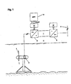
- FIG. 1 shows a possible embodiment of a generic Unterwesserkraftwerks 1 with a device according to the invention for Lelstungsregelung.
- the underwater power plant 1 comprises a water turbine 2 and an electric generator 3, which in the present case is coupled directly to the water turbine 2 and is thus connected to it with a high rotational speed.
- a frequency converter 5 For feeding the electric power generated by the electric generator 3 in a composite network 4 with a constant mains frequency, a frequency converter 5 is used, which in the present case comprises a generator-side converter 6, a DC clamping circuit 7 and a network-side converter 8.
- a first controller 12 is provided for controlling the frequency converter 5, which is assigned to the generator side inverter 6, and a second controller 13 for the power converter 8.
- the two controllers operate independently of each other, the first controller 12 for the generator-side converter 6 determines the load torque on the electric generator 3 and the second controller 13 for the mains converter 8 stabilizes the voltage in the DC intermediate circuit 7, the first controller 12 and the second controller 13 are typically integrated into the respective inverter 6, 8.
- the device for searching for the maximum power 14 determines from the first controller 12 for the generator-side converter 6 present power data P of the electric generator 3 a desired value input for the load torque M soll and outputs this to the first controller 12 back, where the setpoint varies over time.
- the generator-side converter 6 Starting from the predetermined setpoint value for the load torque M soll , the generator-side converter 6 regulates and / or controls the load current at the electric generator 3 of the underwater power plant.
- the load current and, as a result, the load torque can be adjusted by controlling or controlling the stator voltage components d, q in the 2-axis system of the synchronous machine.
- the optimum performance is present at the operating point B, to which the moment M 1 is assigned.
- the MPP controller first of all sets a first setpoint value, which is too low for the load moment M soll , so that after the dynamic effects have faded, the water turbine reaches the operating point C, which moves towards the operating range B towards the cutting edge is.
- a variation of the setpoint for the load torque M soll then leads to a system response to the electric power output by the electric generator 2, so that an assigned power gradient can be determined as a function of the load torque and the MPP controller causes an incremental adjustment of the load torque on the electric generator 2 until the power-optimal operating point B is reached.
- the operating point D for which the MPP controller first against the power-optimal value attaches too high a load torque, which is successively reduced to the operating point B.
- FIG. 2 it is off FIG. 2 the case can be seen that an increase of the Anströmungsgeschwindigkelt enters the water turbine.
- the transition from the characteristic curve V 1 to V 2 from the operating point B to the operating point E is sketched with an arrow. This occurs assuming that initially an unchanged load moment M 1 is generated by the electric generator 3.
- the hydrodynamic moment taken up by the water turbine 2 at the speed n 1 will then initially exceed the load torque, so that the rotating unit accelerates until at speed n 2 a new moment equilibrium is reached.
- the MPP controller will subsequently output a setpoint for the load torque that increases over time, so that a new performance-optimal operating point is found.
- the search direction is in FIG. 2 indicated by an arrow, which indicates the optimum torque 10 torque.
- the power control is performed in the first performance-optimized operating range at turbine speeds that are greater than the maximum torque of the turbine 9 associated speeds.
- the method according to the invention or the device according to the invention comprises a possibility for monitoring the power generation in order to reliably prevent the application of a load torque exceeding the overturning moment on the water turbine.
- the entirety of the braking moments must not exceed the maximum torque for the present flow velocity. However, if this is the case for a short time, it is necessary to counteract this directly by abruptly lowering the load moment on the electric generator 3 in order to ensure the renewed run-up of the water turbine 2.
- the inventive method comprises the following steps to activate the underwater power plant 1 from standstill or idle operation.
- a start-up phase is initially run through, in which the water turbine 2 is started up and accelerated into the high-speed area.
- FIG. 2 the working point A is sketched.
- the water turbine 2 is initially driven by the motor operation of the electric generator 3 and only above a certain speed gradient, the run-up exclusively by the hydrodynamic torque absorbed by the water turbine 2 causes.
- the run-up of the water turbine 2 is carried out so far that the speed gradient initially falls below a threshold before the start-up phase is completed and the Transition to the first, optimized-optimized operating range takes place.
- the water turbine 2 can be guided close to the passage speed, it being possible to deduce the driving flow speed from the turbine door speed thus achieved.
- a first estimated value for the power-optimal load torque for the then coming into effect MPP controller can set, which slows the water turbine 2 by applying a generator load and leads to the power optimal operating point.
- FIG. 2 dash-dotted lines the predetermined in the second, power-limited operating range load torque for Abregelung 11 shown.
- the switching between the operating areas takes place when the nominal rated power is reached.
- the load torque on the electric generator is preferably reduced.
- the operating point F sketched is this in FIG. 2 the operating point F sketched. Accordingly, the rotating unit of the underwater power plant 1 is accelerated until the water turbine 2 receives a reduced hydrodynamic moment in the high-speed area, which generates a moment equilibrium to the impressed load torque.
- the load torque on the electric generator 3 can be adjusted in different ways.
Landscapes
- Engineering & Computer Science (AREA)
- Chemical & Material Sciences (AREA)
- Combustion & Propulsion (AREA)
- Mechanical Engineering (AREA)
- General Engineering & Computer Science (AREA)
- Power Engineering (AREA)
- Control Of Eletrric Generators (AREA)
- Control Of Water Turbines (AREA)
- Other Liquid Machine Or Engine Such As Wave Power Use (AREA)
Claims (14)
- Procédé d'exploitation d'une centrale immergée (1) comportant une turbine à eau (2) permettant d'absorber l'énergie cinétique provenant d'un courant environnant ; et
un générateur électrique (3) couplé directement à la turbine à eau (2) ;
caractérisé en ce que la puissance est régulée pendant le fonctionnement sur générateur en commandant ou régulant le couple de charge produit par le générateur électrique (3) lorsque la vitesse de rotation de la turbine à eau (2) s'établit librement,
où dans une première plage d'exploitation, la valeur de consigne du couple de charge (Mson) est définie par un régulateur de statut et/ou un autre dispositif permettant de rechercher la puissance maximale (14) en présence de la vitesse de circulation, puissance maximale représentant simultanément le maximum du couple hydrodynamique (9) ; et
dans une seconde plage d'exploitation limitée en puissance le couple de charge prédéterminé est choisi de telle sorte que l'on obtient un point de travail éloigné de la puissance maximale pour la turbine à eau (2), point de travail qui se décale (10) vers des vitesses de rotation plus élevées par rapport à la puissance maximale. - Procédé selon la revendication 1, caractérisé en ce que le dispositif de recherche de la puissance maximale (14) comporte un régulateur MPP qui génère une valeur de consigne variable dans le temps pour le couple de charge (Mson) pour maximiser la puissance de sortie du générateur électrique (3).
- Procédé selon l'une des revendications 1 ou 2, caractérisé en ce que l'on utilise comme générateur électrique (3) une machine synchrone excitée par un aimant permanent et que l'on produit le couple de charge par régulation ou contrôle de la tension stator dans le système à deux axes de la machine synchrone.
- Procédé selon l'une des revendications 1 ou 2, caractérisé en ce qu'un convertisseur de fréquence (5) est affecté au générateur électrique (3) convertisseur assurant l'alimentation électrique à une fréquence fixe dans un réseau interconnecté (4), où le couple de charge du générateur électrique (3) est défini par le convertisseur de fréquence (5).
- Procédé selon la revendication 4, caractérisé en ce que le convertisseur de fréquence (5) comprend un convertisseur (6) côté générateur, un circuit intermédiaire à courant continu (7) et un convertisseur (8) côté réseau, où les convertisseurs fonctionnent (6, 7) indépendamment l'un de l'autre et le convertisseur (6) côté générateur définit le couple de charge au niveau du générateur électrique (3) et le convertisseur (8) côté réseau stabilise la tension dans le circuit intermédiaire à courant continu (7).
- Procédé selon la revendication 5, caractérisé en ce que l'on calcule le produit de la tension de circuit intermédiaire et du courant de charge dans le circuit intermédiaire à courant continu (7) pour déterminer la puissance de sortie (P) du générateur électrique (3).
- Procédé selon la revendication 5, caractérisé en ce que l'on calcule le produit du couple de générateur et de la vitesse de rotation du générateur à l'aide du convertisseur côté générateur pour définir la puissance de sortie (P) du générateur électrique (3).
- Procédé selon l'une des revendications 1 ou 2, caractérisé en ce que le couple de charge variable dans le temps présente une part de charge oscillante.
- Procédé selon l'une des revendications 1 ou 2, caractérisé en ce que dans une troisième plage d'exploitation, servant à l'activation de la centrale immergée (1) à partir de l'arrêt ou du ralenti, la turbine à eau (2) accélère dans un premier temps pour atteindre la plage de vitesse élevée avant la transition vers la première plage d'exploitation de puissance optimisée.
- Procédé selon la revendication 9, caractérisé en ce que la turbine à eau (2) va accélérer à l'aide du générateur électrique (3) en fonctionnement sur moteur au début de la phase de démarrage et l'entraînement motorisé est arrêté par le générateur électrique (3) en cas de dépassement d'un seuil pour le gradient de vitesse de rotation et l'emballement de la vitesse de rotation est provoqué exclusivement par le couple hydrodynamique absorbé par la turbine à eau (2).
- Procédé selon la revendication 10, caractérisé en ce que l'on maintient la phase de démarrage jusqu'à ce que le gradient de vitesse de rotation de l'emballement provoqué par le couple hydrodynamique tombe au-dessous d'une valeur minimale prédéterminée, valeur que l'on choisit pour que la turbine à eau (2) se rapproche de la vitesse d'emballement.
- Procédé selon la revendication 11, caractérisé en ce que l'on utilise la vitesse de rotation de la turbine à eau (2) obtenue au terme de la phase de démarrage pour déterminer une première estimation du couple de charge de puissance optimale.
- Procédé selon l'une des revendications 1 ou 2, caractérisé en ce que l'on diagnostique le cas d'un couple de charge choisi trop élevé, couple qui dépasse le couple de basculement de la turbine à eau (2) et a ainsi pour effet de réduire par saccades le couple de charge au niveau du générateur électrique (3).
- Procédé selon l'une quelconque des revendications précédentes, caractérisé en ce que le procédé met l'installation à l'arrêt dans la première plage d'exploitation de puissance optimisée lorsque la valeur de consigne du couple de charge tombe au-dessous d'un couple minimal prédéterminé.
Applications Claiming Priority (1)
| Application Number | Priority Date | Filing Date | Title |
|---|---|---|---|
| DE102008053732A DE102008053732B8 (de) | 2008-10-29 | 2008-10-29 | Verfahren und Vorrichtung für die Leistungsregelung eines Unterwasserkraftwerks |
Publications (3)
| Publication Number | Publication Date |
|---|---|
| EP2182200A2 EP2182200A2 (fr) | 2010-05-05 |
| EP2182200A3 EP2182200A3 (fr) | 2013-08-14 |
| EP2182200B1 true EP2182200B1 (fr) | 2015-02-11 |
Family
ID=41259781
Family Applications (1)
| Application Number | Title | Priority Date | Filing Date |
|---|---|---|---|
| EP09013190.5A Not-in-force EP2182200B1 (fr) | 2008-10-29 | 2009-10-20 | Procédé et dispositif pour le contrôle de la puissance d'une centrale électrique submergée |
Country Status (7)
| Country | Link |
|---|---|
| US (2) | US20100109325A1 (fr) |
| EP (1) | EP2182200B1 (fr) |
| KR (1) | KR20100047810A (fr) |
| AU (1) | AU2009227898B2 (fr) |
| CA (1) | CA2683338A1 (fr) |
| DE (1) | DE102008053732B8 (fr) |
| NZ (1) | NZ580705A (fr) |
Families Citing this family (27)
| Publication number | Priority date | Publication date | Assignee | Title |
|---|---|---|---|---|
| DE102008053732B8 (de) * | 2008-10-29 | 2013-10-02 | Voith Patent Gmbh | Verfahren und Vorrichtung für die Leistungsregelung eines Unterwasserkraftwerks |
| AT509497B1 (de) * | 2010-03-02 | 2018-09-15 | Astra Vermoegens Und Beteiligungsverwaltungsgesellschaft Mbh | Wasserkraftmaschine |
| DE102010015534A1 (de) * | 2010-04-16 | 2011-10-20 | Voith Patent Gmbh | Strömungskraftwerk und Verfahren für dessen Betrieb |
| ES2536231T3 (es) * | 2010-08-13 | 2015-05-21 | Vestas Wind Systems A/S | Producción de energía eólica con fluctuaciones de potencia reducidas |
| DE102010063276A1 (de) | 2010-12-16 | 2012-06-21 | Aktiebolaget Skf | Axiallagerscheibensegment, Axiallagerscheibe, Antriebswelle und Montageverfahren |
| DE102010063278A1 (de) | 2010-12-16 | 2012-06-21 | Aktiebolaget Skf | Axiallagerscheibensegment, Axiallagerscheibe und Herstellungsverfahren |
| DE102010063275A1 (de) | 2010-12-16 | 2012-06-21 | Aktiebolaget Skf | Lagerringsegment, Lagerring, Lager, Antriebswelle und Montageverfahren |
| GB2483315B (en) * | 2010-12-23 | 2012-07-25 | Tidal Generation Ltd | Control of water current turbines |
| KR101030748B1 (ko) * | 2011-01-26 | 2011-04-26 | 석영환 | 수류 유도 구조 및 발전터빈 분리 구조를 가진 조류발전기 |
| DE102011003226A1 (de) | 2011-01-27 | 2012-08-02 | Aktiebolaget Skf | Lagerringsegment, Lagerring, Lager, Antriebswelle und Unterwasserkraftwerk |
| DE102011101368A1 (de) | 2011-05-12 | 2012-11-15 | Voith Patent Gmbh | Strömungskraftwerk und Verfahren für dessen Betrieb |
| DE102011107286A1 (de) | 2011-07-06 | 2013-01-10 | Voith Patent Gmbh | Strömungskraftwerk und Verfahren für dessen Betrieb |
| GB2493711B (en) * | 2011-08-12 | 2018-04-25 | Openhydro Ip Ltd | Method and system for controlling hydroelectric turbines |
| DE102011114438A1 (de) | 2011-09-28 | 2013-03-28 | Voith Patent Gmbh | Betriebsverfahren für ein Strömungskraftwerk und Steuerungseinrichtung zur Ausführung des Verfahrens |
| DE102011085611A1 (de) | 2011-11-02 | 2013-05-02 | Aktiebolaget Skf | Lagerkomponente, Lager, Antriebswelle und Unterwasserkraftwerk |
| DE102011085612A1 (de) | 2011-11-02 | 2013-05-02 | Aktiebolaget Skf | Reibscheibenkomponente, Anordnung und Unterwasserkraftwerk |
| GB2485282B (en) * | 2011-11-10 | 2013-09-25 | Tidal Generation Ltd | Control of water current turbines |
| US9328713B2 (en) | 2012-04-13 | 2016-05-03 | Steven D. Beaston | Turbine apparatus and methods |
| DE102012224188A1 (de) * | 2012-12-21 | 2014-06-26 | Wobben Properties Gmbh | Verfahren zur Steuerung eines Wasserschütz-Antriebs für ein Wasserschütz mit einer elektrischen Maschine, Betriebsschaltung, Wasserschütz-Antrieb und Wasserkraftanlage |
| US8777555B1 (en) * | 2013-02-21 | 2014-07-15 | Lockheed Martin Corporation | Yaw drive tidal turbine system and method |
| ITRM20130272A1 (it) * | 2013-05-08 | 2014-11-09 | Consiglio Nazionale Ricerche | Metodo e relativo sistema per la conversione di energia meccanica, proveniente da un generatore comandato da una turbina, in energia elettrica. |
| GB2521631B (en) * | 2013-12-23 | 2017-10-11 | Tidal Generation Ltd | Water current power generation systems |
| JP6048595B2 (ja) * | 2014-07-28 | 2016-12-21 | 株式会社明電舎 | 発電装置の自立運転方法 |
| JP6641802B2 (ja) * | 2015-09-03 | 2020-02-05 | 株式会社明電舎 | 発電システムの系統連系運転装置と制御方法 |
| DE102015222666A1 (de) * | 2015-11-17 | 2017-05-18 | Rwe Power Aktiengesellschaft | Verfahren zum Betrieb eines Laufwasserkraftwerks |
| US10718598B2 (en) * | 2017-06-23 | 2020-07-21 | Hamilton Sundstrand Corporation | Series hybrid architecture for an unmanned underwater vehicle propulsion system |
| DE102021106494A1 (de) * | 2021-03-17 | 2022-09-22 | Harald Kuhn | Energieerzeugungsvorrichtung |
Family Cites Families (21)
| Publication number | Priority date | Publication date | Assignee | Title |
|---|---|---|---|---|
| DE3601288A1 (de) * | 1986-01-17 | 1987-07-23 | Siemens Ag | Wassergetriebener maschinensatz mit wirkungsgradoptimaler vorgabe des drehzahlsollwertes |
| DE3601289A1 (de) * | 1986-01-17 | 1987-07-23 | Siemens Ag | Leistungsregelung eines wassergetriebenen maschinensatzes |
| US4868408A (en) * | 1988-09-12 | 1989-09-19 | Frank Hesh | Portable water-powered electric generator |
| US5742515A (en) * | 1995-04-21 | 1998-04-21 | General Electric Co. | Asynchronous conversion method and apparatus for use with variable speed turbine hydroelectric generation |
| US5798572A (en) * | 1996-04-15 | 1998-08-25 | Lehoczky; Kalman N. | Under water hydro-turbine energy generator design |
| US6104097A (en) * | 1999-03-04 | 2000-08-15 | Lehoczky; Kalman N. | Underwater hydro-turbine for hydrogen production |
| US6531788B2 (en) * | 2001-02-22 | 2003-03-11 | John H. Robson | Submersible electrical power generating plant |
| US20030218338A1 (en) * | 2002-05-23 | 2003-11-27 | O'sullivan George A. | Apparatus and method for extracting maximum power from flowing water |
| GB0222466D0 (en) * | 2002-09-27 | 2002-11-06 | Marine Current Turbines Ltd | Improvements in rotor blades and/or hydrofoils |
| GB0227739D0 (en) * | 2002-11-28 | 2003-01-08 | Marine Current Turbines Ltd | Supporting structures for water current (including tidal stream) turbines |
| US6935808B1 (en) * | 2003-03-17 | 2005-08-30 | Harry Edward Dempster | Breakwater |
| US7042110B2 (en) * | 2003-05-07 | 2006-05-09 | Clipper Windpower Technology, Inc. | Variable speed distributed drive train wind turbine system |
| US7077072B2 (en) * | 2003-12-11 | 2006-07-18 | Honeywell International, Inc. | Unmanned underwater vehicle turbine powered charging system and method |
| US7471006B2 (en) * | 2005-09-12 | 2008-12-30 | Gulfstream Technologies, Inc. | Apparatus and method for generating electric power from a subsurface water current |
| US7291936B1 (en) * | 2006-05-03 | 2007-11-06 | Robson John H | Submersible electrical power generating plant |
| GB2441769B (en) * | 2006-09-12 | 2011-05-18 | Limited Tidal Generation | Water current power generating devices |
| DE102007013293B3 (de) * | 2007-03-16 | 2008-06-26 | Voith Patent Gmbh | Verfahren und Vorrichtung zum Betrieb eines Unterwasserkraftwerks |
| US8303241B2 (en) * | 2007-11-13 | 2012-11-06 | Verdant Power, Inc. | Turbine yaw control |
| US7936077B2 (en) * | 2008-05-19 | 2011-05-03 | Lehoczky Kalman N | Internal fluid handling for hydro-generator submerged in water |
| DE102008053732B8 (de) * | 2008-10-29 | 2013-10-02 | Voith Patent Gmbh | Verfahren und Vorrichtung für die Leistungsregelung eines Unterwasserkraftwerks |
| US7821153B2 (en) * | 2009-02-09 | 2010-10-26 | Grayhawke Applied Technologies | System and method for generating electricity |
-
2008
- 2008-10-29 DE DE102008053732A patent/DE102008053732B8/de not_active Expired - Fee Related
-
2009
- 2009-10-20 EP EP09013190.5A patent/EP2182200B1/fr not_active Not-in-force
- 2009-10-21 US US12/589,301 patent/US20100109325A1/en not_active Abandoned
- 2009-10-22 CA CA2683338A patent/CA2683338A1/fr not_active Abandoned
- 2009-10-22 AU AU2009227898A patent/AU2009227898B2/en not_active Ceased
- 2009-10-23 NZ NZ580705A patent/NZ580705A/en not_active IP Right Cessation
- 2009-10-28 KR KR1020090102604A patent/KR20100047810A/ko not_active Ceased
-
2013
- 2013-03-27 US US13/851,851 patent/US8674535B2/en not_active Expired - Fee Related
Also Published As
| Publication number | Publication date |
|---|---|
| CA2683338A1 (fr) | 2010-04-29 |
| AU2009227898A1 (en) | 2010-05-13 |
| DE102008053732B8 (de) | 2013-10-02 |
| US20100109325A1 (en) | 2010-05-06 |
| AU2009227898B2 (en) | 2014-05-29 |
| EP2182200A3 (fr) | 2013-08-14 |
| EP2182200A2 (fr) | 2010-05-05 |
| KR20100047810A (ko) | 2010-05-10 |
| NZ580705A (en) | 2011-03-31 |
| DE102008053732B3 (de) | 2010-01-21 |
| US20130214533A1 (en) | 2013-08-22 |
| US8674535B2 (en) | 2014-03-18 |
Similar Documents
| Publication | Publication Date | Title |
|---|---|---|
| DE102008053732B3 (de) | Verfahren und Vorrichtung für die Leistungsregelung eines Unterwasserkraftwerks | |
| DE10361443B4 (de) | Regelung für eine Windkraftanlage mit hydrodynamischem Getriebe | |
| EP3644497B1 (fr) | Procédé et dispositif de commande virtuelle d'inertie de masse pour centrales pourvues de machine asynchrone à double alimentation | |
| DE102013100385B4 (de) | 3Verfahren zum Betreiben einer Windenergieanlage | |
| EP1608872B1 (fr) | Chaine cinematique pour transmettre une puissance variable | |
| EP2556247B1 (fr) | Régulation d'inertie dynamique | |
| EP1756423B1 (fr) | Installation de production d'energie avec une transmission a vitesse reglable | |
| EP2247850B1 (fr) | Centrale houlomotrice et son procédé de fonctionnement | |
| EP2017473B1 (fr) | Eolienne dotée d'une plage de vitesses de rotation étendue | |
| EP1538739A2 (fr) | Ligne d'entraínement pour une machine de conversion de flux | |
| EP1407141A1 (fr) | Procede et dispositif pour reguler la vitesse de rotation d'une eolienne sans multiplicateur, au moyen de dispositifs electroniques de puissance | |
| EP2505828B1 (fr) | Procédé de fonctionnement d'une éolienne | |
| EP3512064B1 (fr) | Commande d'une aérogenerateur par modification des paramètres de vitesse de rotation | |
| EP3810924B1 (fr) | Fonctionnement à puissance réduite d'une éolienne | |
| DE102010005286A1 (de) | Windenergieanlage mit Zusatzverbraucher, insbesondere Blattheizungsvorrichtung, und Betriebsverfahren hierzu | |
| AT511782A1 (de) | Energiegewinnungsanlage, insbesondere windkraftanlage | |
| EP1875593B1 (fr) | Procede et dispositif pour utiliser l'energie eolienne | |
| EP3952102B1 (fr) | Réglage du moteur protégé contre les surcharges | |
| WO2004094872A1 (fr) | Chaine cinematique a vitesse d'entree variable et a vitesse de sortie constante | |
| Brando et al. | An efficient power control strategy for small fixed-pitch wind turbine to extend the operating range to high wind speed region | |
| DE102015111520A1 (de) | Steuersystem für Windkraftanlagen, mit verbesserter Reaktionsfähigkeit gegenüber Windböen | |
| DE102023202770A1 (de) | Zwischenspeichereinrichtung für ein Energienetz | |
| DE102023202769A1 (de) | Rotierender Phasenschieber mit variabler Übersetzung | |
| EP4177460A1 (fr) | Procédé de refroidissement efficace d'une éolienne |
Legal Events
| Date | Code | Title | Description |
|---|---|---|---|
| PUAI | Public reference made under article 153(3) epc to a published international application that has entered the european phase |
Free format text: ORIGINAL CODE: 0009012 |
|
| AK | Designated contracting states |
Kind code of ref document: A2 Designated state(s): AT BE BG CH CY CZ DE DK EE ES FI FR GB GR HR HU IE IS IT LI LT LU LV MC MK MT NL NO PL PT RO SE SI SK SM TR |
|
| AX | Request for extension of the european patent |
Extension state: AL BA RS |
|
| PUAL | Search report despatched |
Free format text: ORIGINAL CODE: 0009013 |
|
| AK | Designated contracting states |
Kind code of ref document: A3 Designated state(s): AT BE BG CH CY CZ DE DK EE ES FI FR GB GR HR HU IE IS IT LI LT LU LV MC MK MT NL NO PL PT RO SE SI SK SM TR |
|
| AX | Request for extension of the european patent |
Extension state: AL BA RS |
|
| RIC1 | Information provided on ipc code assigned before grant |
Ipc: F03B 15/06 20060101ALI20130710BHEP Ipc: F03B 13/10 20060101ALI20130710BHEP Ipc: F03B 17/06 20060101ALI20130710BHEP Ipc: F03B 15/16 20060101ALI20130710BHEP Ipc: H02P 9/48 20060101ALI20130710BHEP Ipc: F03B 15/04 20060101AFI20130710BHEP |
|
| RIN1 | Information on inventor provided before grant (corrected) |
Inventor name: HOELLE, MICHAEL Inventor name: ARLITT, RAPHAEL, DR. |
|
| 17P | Request for examination filed |
Effective date: 20131118 |
|
| RBV | Designated contracting states (corrected) |
Designated state(s): AT BE BG CH CY CZ DE DK EE ES FI FR GB GR HR HU IE IS IT LI LT LU LV MC MK MT NL NO PL PT RO SE SI SK SM TR |
|
| GRAP | Despatch of communication of intention to grant a patent |
Free format text: ORIGINAL CODE: EPIDOSNIGR1 |
|
| INTG | Intention to grant announced |
Effective date: 20140929 |
|
| GRAS | Grant fee paid |
Free format text: ORIGINAL CODE: EPIDOSNIGR3 |
|
| GRAA | (expected) grant |
Free format text: ORIGINAL CODE: 0009210 |
|
| AK | Designated contracting states |
Kind code of ref document: B1 Designated state(s): AT BE BG CH CY CZ DE DK EE ES FI FR GB GR HR HU IE IS IT LI LT LU LV MC MK MT NL NO PL PT RO SE SI SK SM TR |
|
| REG | Reference to a national code |
Ref country code: GB Ref legal event code: FG4D Free format text: NOT ENGLISH |
|
| REG | Reference to a national code |
Ref country code: CH Ref legal event code: EP |
|
| REG | Reference to a national code |
Ref country code: IE Ref legal event code: FG4D Free format text: LANGUAGE OF EP DOCUMENT: GERMAN |
|
| REG | Reference to a national code |
Ref country code: AT Ref legal event code: REF Ref document number: 710021 Country of ref document: AT Kind code of ref document: T Effective date: 20150315 |
|
| REG | Reference to a national code |
Ref country code: DE Ref legal event code: R096 Ref document number: 502009010590 Country of ref document: DE Effective date: 20150326 |
|
| REG | Reference to a national code |
Ref country code: NL Ref legal event code: VDEP Effective date: 20150211 |
|
| REG | Reference to a national code |
Ref country code: LT Ref legal event code: MG4D |
|
| PG25 | Lapsed in a contracting state [announced via postgrant information from national office to epo] |
Ref country code: NO Free format text: LAPSE BECAUSE OF FAILURE TO SUBMIT A TRANSLATION OF THE DESCRIPTION OR TO PAY THE FEE WITHIN THE PRESCRIBED TIME-LIMIT Effective date: 20150511 Ref country code: FI Free format text: LAPSE BECAUSE OF FAILURE TO SUBMIT A TRANSLATION OF THE DESCRIPTION OR TO PAY THE FEE WITHIN THE PRESCRIBED TIME-LIMIT Effective date: 20150211 Ref country code: ES Free format text: LAPSE BECAUSE OF FAILURE TO SUBMIT A TRANSLATION OF THE DESCRIPTION OR TO PAY THE FEE WITHIN THE PRESCRIBED TIME-LIMIT Effective date: 20150211 Ref country code: SE Free format text: LAPSE BECAUSE OF FAILURE TO SUBMIT A TRANSLATION OF THE DESCRIPTION OR TO PAY THE FEE WITHIN THE PRESCRIBED TIME-LIMIT Effective date: 20150211 Ref country code: HR Free format text: LAPSE BECAUSE OF FAILURE TO SUBMIT A TRANSLATION OF THE DESCRIPTION OR TO PAY THE FEE WITHIN THE PRESCRIBED TIME-LIMIT Effective date: 20150211 Ref country code: LT Free format text: LAPSE BECAUSE OF FAILURE TO SUBMIT A TRANSLATION OF THE DESCRIPTION OR TO PAY THE FEE WITHIN THE PRESCRIBED TIME-LIMIT Effective date: 20150211 |
|
| PG25 | Lapsed in a contracting state [announced via postgrant information from national office to epo] |
Ref country code: NL Free format text: LAPSE BECAUSE OF FAILURE TO SUBMIT A TRANSLATION OF THE DESCRIPTION OR TO PAY THE FEE WITHIN THE PRESCRIBED TIME-LIMIT Effective date: 20150211 Ref country code: IS Free format text: LAPSE BECAUSE OF FAILURE TO SUBMIT A TRANSLATION OF THE DESCRIPTION OR TO PAY THE FEE WITHIN THE PRESCRIBED TIME-LIMIT Effective date: 20150611 Ref country code: LV Free format text: LAPSE BECAUSE OF FAILURE TO SUBMIT A TRANSLATION OF THE DESCRIPTION OR TO PAY THE FEE WITHIN THE PRESCRIBED TIME-LIMIT Effective date: 20150211 Ref country code: GR Free format text: LAPSE BECAUSE OF FAILURE TO SUBMIT A TRANSLATION OF THE DESCRIPTION OR TO PAY THE FEE WITHIN THE PRESCRIBED TIME-LIMIT Effective date: 20150512 |
|
| PG25 | Lapsed in a contracting state [announced via postgrant information from national office to epo] |
Ref country code: CZ Free format text: LAPSE BECAUSE OF FAILURE TO SUBMIT A TRANSLATION OF THE DESCRIPTION OR TO PAY THE FEE WITHIN THE PRESCRIBED TIME-LIMIT Effective date: 20150211 Ref country code: DK Free format text: LAPSE BECAUSE OF FAILURE TO SUBMIT A TRANSLATION OF THE DESCRIPTION OR TO PAY THE FEE WITHIN THE PRESCRIBED TIME-LIMIT Effective date: 20150211 Ref country code: SK Free format text: LAPSE BECAUSE OF FAILURE TO SUBMIT A TRANSLATION OF THE DESCRIPTION OR TO PAY THE FEE WITHIN THE PRESCRIBED TIME-LIMIT Effective date: 20150211 Ref country code: EE Free format text: LAPSE BECAUSE OF FAILURE TO SUBMIT A TRANSLATION OF THE DESCRIPTION OR TO PAY THE FEE WITHIN THE PRESCRIBED TIME-LIMIT Effective date: 20150211 Ref country code: RO Free format text: LAPSE BECAUSE OF FAILURE TO SUBMIT A TRANSLATION OF THE DESCRIPTION OR TO PAY THE FEE WITHIN THE PRESCRIBED TIME-LIMIT Effective date: 20150211 |
|
| REG | Reference to a national code |
Ref country code: DE Ref legal event code: R097 Ref document number: 502009010590 Country of ref document: DE |
|
| PG25 | Lapsed in a contracting state [announced via postgrant information from national office to epo] |
Ref country code: PL Free format text: LAPSE BECAUSE OF FAILURE TO SUBMIT A TRANSLATION OF THE DESCRIPTION OR TO PAY THE FEE WITHIN THE PRESCRIBED TIME-LIMIT Effective date: 20150211 |
|
| PLBE | No opposition filed within time limit |
Free format text: ORIGINAL CODE: 0009261 |
|
| STAA | Information on the status of an ep patent application or granted ep patent |
Free format text: STATUS: NO OPPOSITION FILED WITHIN TIME LIMIT |
|
| PG25 | Lapsed in a contracting state [announced via postgrant information from national office to epo] |
Ref country code: IT Free format text: LAPSE BECAUSE OF FAILURE TO SUBMIT A TRANSLATION OF THE DESCRIPTION OR TO PAY THE FEE WITHIN THE PRESCRIBED TIME-LIMIT Effective date: 20150211 |
|
| 26N | No opposition filed |
Effective date: 20151112 |
|
| PG25 | Lapsed in a contracting state [announced via postgrant information from national office to epo] |
Ref country code: SI Free format text: LAPSE BECAUSE OF FAILURE TO SUBMIT A TRANSLATION OF THE DESCRIPTION OR TO PAY THE FEE WITHIN THE PRESCRIBED TIME-LIMIT Effective date: 20150211 |
|
| REG | Reference to a national code |
Ref country code: DE Ref legal event code: R119 Ref document number: 502009010590 Country of ref document: DE |
|
| PG25 | Lapsed in a contracting state [announced via postgrant information from national office to epo] |
Ref country code: LU Free format text: LAPSE BECAUSE OF FAILURE TO SUBMIT A TRANSLATION OF THE DESCRIPTION OR TO PAY THE FEE WITHIN THE PRESCRIBED TIME-LIMIT Effective date: 20151020 |
|
| REG | Reference to a national code |
Ref country code: CH Ref legal event code: PL |
|
| GBPC | Gb: european patent ceased through non-payment of renewal fee |
Effective date: 20151020 |
|
| PG25 | Lapsed in a contracting state [announced via postgrant information from national office to epo] |
Ref country code: MC Free format text: LAPSE BECAUSE OF FAILURE TO SUBMIT A TRANSLATION OF THE DESCRIPTION OR TO PAY THE FEE WITHIN THE PRESCRIBED TIME-LIMIT Effective date: 20150211 |
|
| REG | Reference to a national code |
Ref country code: IE Ref legal event code: MM4A |
|
| PG25 | Lapsed in a contracting state [announced via postgrant information from national office to epo] |
Ref country code: DE Free format text: LAPSE BECAUSE OF NON-PAYMENT OF DUE FEES Effective date: 20160503 Ref country code: GB Free format text: LAPSE BECAUSE OF NON-PAYMENT OF DUE FEES Effective date: 20151020 Ref country code: LI Free format text: LAPSE BECAUSE OF NON-PAYMENT OF DUE FEES Effective date: 20151031 Ref country code: CH Free format text: LAPSE BECAUSE OF NON-PAYMENT OF DUE FEES Effective date: 20151031 |
|
| REG | Reference to a national code |
Ref country code: FR Ref legal event code: ST Effective date: 20160630 |
|
| PG25 | Lapsed in a contracting state [announced via postgrant information from national office to epo] |
Ref country code: FR Free format text: LAPSE BECAUSE OF NON-PAYMENT OF DUE FEES Effective date: 20151102 |
|
| PG25 | Lapsed in a contracting state [announced via postgrant information from national office to epo] |
Ref country code: IE Free format text: LAPSE BECAUSE OF NON-PAYMENT OF DUE FEES Effective date: 20151020 |
|
| REG | Reference to a national code |
Ref country code: AT Ref legal event code: MM01 Ref document number: 710021 Country of ref document: AT Kind code of ref document: T Effective date: 20151020 |
|
| PG25 | Lapsed in a contracting state [announced via postgrant information from national office to epo] |
Ref country code: AT Free format text: LAPSE BECAUSE OF NON-PAYMENT OF DUE FEES Effective date: 20151020 |
|
| PG25 | Lapsed in a contracting state [announced via postgrant information from national office to epo] |
Ref country code: SM Free format text: LAPSE BECAUSE OF FAILURE TO SUBMIT A TRANSLATION OF THE DESCRIPTION OR TO PAY THE FEE WITHIN THE PRESCRIBED TIME-LIMIT Effective date: 20150211 Ref country code: BG Free format text: LAPSE BECAUSE OF FAILURE TO SUBMIT A TRANSLATION OF THE DESCRIPTION OR TO PAY THE FEE WITHIN THE PRESCRIBED TIME-LIMIT Effective date: 20150211 Ref country code: HU Free format text: LAPSE BECAUSE OF FAILURE TO SUBMIT A TRANSLATION OF THE DESCRIPTION OR TO PAY THE FEE WITHIN THE PRESCRIBED TIME-LIMIT; INVALID AB INITIO Effective date: 20091020 |
|
| PG25 | Lapsed in a contracting state [announced via postgrant information from national office to epo] |
Ref country code: CY Free format text: LAPSE BECAUSE OF FAILURE TO SUBMIT A TRANSLATION OF THE DESCRIPTION OR TO PAY THE FEE WITHIN THE PRESCRIBED TIME-LIMIT Effective date: 20150211 |
|
| PG25 | Lapsed in a contracting state [announced via postgrant information from national office to epo] |
Ref country code: BE Free format text: LAPSE BECAUSE OF NON-PAYMENT OF DUE FEES Effective date: 20151031 |
|
| PG25 | Lapsed in a contracting state [announced via postgrant information from national office to epo] |
Ref country code: TR Free format text: LAPSE BECAUSE OF FAILURE TO SUBMIT A TRANSLATION OF THE DESCRIPTION OR TO PAY THE FEE WITHIN THE PRESCRIBED TIME-LIMIT Effective date: 20150211 Ref country code: MT Free format text: LAPSE BECAUSE OF FAILURE TO SUBMIT A TRANSLATION OF THE DESCRIPTION OR TO PAY THE FEE WITHIN THE PRESCRIBED TIME-LIMIT Effective date: 20150211 |
|
| PG25 | Lapsed in a contracting state [announced via postgrant information from national office to epo] |
Ref country code: MK Free format text: LAPSE BECAUSE OF FAILURE TO SUBMIT A TRANSLATION OF THE DESCRIPTION OR TO PAY THE FEE WITHIN THE PRESCRIBED TIME-LIMIT Effective date: 20150211 Ref country code: PT Free format text: LAPSE BECAUSE OF FAILURE TO SUBMIT A TRANSLATION OF THE DESCRIPTION OR TO PAY THE FEE WITHIN THE PRESCRIBED TIME-LIMIT Effective date: 20150211 |