EP2182249B1 - Engrenage - Google Patents
Engrenage Download PDFInfo
- Publication number
- EP2182249B1 EP2182249B1 EP09013620A EP09013620A EP2182249B1 EP 2182249 B1 EP2182249 B1 EP 2182249B1 EP 09013620 A EP09013620 A EP 09013620A EP 09013620 A EP09013620 A EP 09013620A EP 2182249 B1 EP2182249 B1 EP 2182249B1
- Authority
- EP
- European Patent Office
- Prior art keywords
- rocker
- point
- guide
- push rod
- gearbox
- Prior art date
- Legal status (The legal status is an assumption and is not a legal conclusion. Google has not performed a legal analysis and makes no representation as to the accuracy of the status listed.)
- Not-in-force
Links
Images

Classifications
-
- F—MECHANICAL ENGINEERING; LIGHTING; HEATING; WEAPONS; BLASTING
- F16—ENGINEERING ELEMENTS AND UNITS; GENERAL MEASURES FOR PRODUCING AND MAINTAINING EFFECTIVE FUNCTIONING OF MACHINES OR INSTALLATIONS; THERMAL INSULATION IN GENERAL
- F16H—GEARING
- F16H21/00—Gearings comprising primarily only links or levers, with or without slides
- F16H21/10—Gearings comprising primarily only links or levers, with or without slides all movement being in, or parallel to, a single plane
- F16H21/44—Gearings comprising primarily only links or levers, with or without slides all movement being in, or parallel to, a single plane for conveying or interconverting oscillating or reciprocating motions
-
- B—PERFORMING OPERATIONS; TRANSPORTING
- B25—HAND TOOLS; PORTABLE POWER-DRIVEN TOOLS; MANIPULATORS
- B25B—TOOLS OR BENCH DEVICES NOT OTHERWISE PROVIDED FOR, FOR FASTENING, CONNECTING, DISENGAGING, OR HOLDING
- B25B5/00—Clamps
- B25B5/14—Clamps for work of special profile
- B25B5/147—Clamps for work of special profile for pipes
Definitions
- the invention relates to a transmission for transmitting rectilinear forces.
- US 2,047,061 describes a mechanism for actuating a valve in which a rocker rolls on a guide contour.
- the mechanism allows the transmission of compressive forces.
- the rocker and the guide contour are provided with interlocking teeth.
- the radii of the rocker and the guide contour are in the ratio 1: 2.
- the rocker is driven by means of a push rod which presses against a seat so that at its opposite end a pressure on a piston of the valve is exerted.
- a counter-movement takes place by a compression spring on the valve presses the piston against it.
- the rocker is pressed by a leaf spring against the guide contour.
- DE 2 804 715 A1 describes a controller for actuating a valve in a cylinder head.
- a rod for moving the valve is articulated to a lever which rolls with a curved with a Wälzradius r fulcrum surface on a rolling surface with twice as large radius. Gears are provided between the fulcrum surface and the rolling surface.
- the movement of the lever is controlled by a servo drive with the help of another rod whose end is hinged to the lever.
- the servo drive can perform a reciprocating movement of the rod.
- On the opposite side of the valve-actuating rod is biased by a compression spring down. Due to the radii ratio of the fulcrum surface and the rolling surface, the points of articulation of the rods lying on the pitch circle of the teeth move in a straight line on the lever.
- the object of the invention is to provide a gear available, which is particularly well suited for transmitting rectilinear forces of a reciprocating motion.
- a point such as the guide point, hinge point or gear fixed point is mentioned, is always a point when viewed in the plane of the rocking motion meant.
- geometrical indications of distances, circle radii or the like refer to a consideration in the plane of the rocking motion, and the respective circular arcs are parallel to this plane.
- the rocker can perform a limited rocking movement in the mentioned plane.
- the positive guidance of the rocker is designed so that not only the guide point of the rocker maintains a constant distance from the gear fixed point, but also the first pivot point performs a straight-ahead reciprocating motion in or parallel to the plane.
- Various constructive variants for effecting this forced operation are described below.
- the transmission thus makes it possible to effect a force transmission between the rocking movement of the rocker and the rectilinear reciprocation of the articulation point to which the push rod is coupled.
- the second drive or driven element may, for example, be a further push rod, which is likewise connected to the rocker at a pivot point, which performs a rectilinear reciprocation.
- the push rod is for example a connecting rod.
- a second push rod forms a second drive or output elements, which second push rod is connected at a second, different from the first hinge point hinge point with the rocker, which performs a linear reciprocating motion parallel to said plane during the rocking movement of the rocker.
- the first push rod serves as a drive element or drive
- the second push rod serves as output elements or output.
- the transmission is designed, for example, for a selectable angle between the direction of rectilinear reciprocation of the first push rod and the direction of rectilinear reciprocation of the second push rod. This angle is for example in the range of 0 to less than 180 °.
- the drive-side transmission angle is preferably greater than 30 °, but less than 180 °.
- the first and second hinge points lie on different sides of the guide point of the rocker.
- the first and second hinge points are in line with the guide point.
- the first and the second hinge point each have the same distance from the guide point in the plane of the rocking motion.
- drives integrated into the transmission. Examples are: a threaded spindle with handwheel or motor, a rack with handwheel or motor, a hydraulic or pneumatic cylinder, a crank mechanism or a crank loop, etc.
- the rocker is forcibly guided by means of a link, wherein the link is pivotable about the guide point and is pivotable about an axis passing through the gear fixed point.
- the handlebar connects the guide point with said gear fixed point.
- the rocker is pivotally connected to the handlebar.
- the handlebar is rotatably mounted about the gear fixed point.
- the link in the plane of the rocking motion performs a pivotal movement about the gearbox-fixed point.
- the handlebar offers a simple, robust and space-saving way to force the guide point of the rocker on a circular arc around the gearbox fixed point.
- the handlebar forms a crank with a rocker arm whose axis passes through the gear fixed point and is arranged perpendicular to said plane.
- the rocker arm can act both as drive or as output. With such a transmission, a power transmission between rectilinear oscillating tensile and compressive forces and oscillating torques can take place.
- a drive via the push rod can be done as in the embodiment described above with two push rods.
- a drive on the rocker arm for example: a three-speed transmission with rotating crank, coupling and rocker, a drive via swash plates and a rotary cylinder.
- the transmission ratio is not constant, so that on the one hand a self-locking and on the other hand a toggle lever effect can be achieved.
- the rocker is guided by means of a rolling element, for example a roller, which rolling element is mounted rotatably about an axis passing through the guide point on the rocker and rolls on a guide link in front of said gear fixed point.
- a rolling element for example a roller
- the guide point of the rocker in the plane of the rocking movement can maintain a constant distance from the gearbox-fixed point.
- the rocker has a circular-segment-shaped convex outer contour with a radius R, by means of which it is guided in a concave guide contour, which is circular section-shaped with a radius 2R.
- the rocker swings with its outer contour with the radius R on an arc with the radius 2R back and forth (rocking movement).
- the positive guidance of the rocker prevents the rocker, for example, during load changes, lifts off the guide contour.
- the outer contour of the rocker and the guide contour each have teeth that intermesh.
- the toothing of the outer contour of the rocker with the guide contour prevents the rocker from slipping along the guide contour.
- a transfer between the oscillatory movement of the rocker and the rectilinear reciprocation of the hinge point takes place.
- the transmission is arranged in a flat housing, from which the push rod (s) and possibly the rocker arm protrude.
- the invention makes it possible to redirect rectilinear tensile and compressive forces exclusively by superimposed rolling and rotating movements.
- the push rods are led out immediately radially outward from the circle portion of the outer guide contour with radius 2R, results in a very compact structure.
- a relatively large stroke is possible, as well as a transmission of large forces.
- Due to the favorable load distribution on the movable elements, in particular the rocker can be inexpensively e.g. be made of plastic.
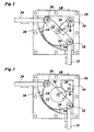
- Fig. 1 shown gear has a housing 10, of which in Fig. 1 a half-shell is shown.
- a rocker 12 is received, which can perform a rocking motion in a plane corresponding to the plane of the drawing.
- the housing On an inner side on the wall of the housing 10, the housing forms a concave guide contour 14 which extends along a circular arc with the radius 2R about a gear fixed point 16 and in the example shown corresponds approximately to a quarter circle.
- An area of the guide contour 14 is provided with teeth 18.
- the rocker 12 has a convex, circular arc-shaped outer contour 20 which extends with a radius R to a guide point 22 of the rocker.
- the outer contour 20 corresponds approximately to a semicircle and is provided with teeth 24, by means of which the rocker 12 is toothed with the guide contour 14. Thus, the rocker 12 must roll on the guide contour 14.
- the rocker at the guide point 22 is pivotally connected to a handlebar 26, which in turn is pivotally connected to the housing 10 at the gear fixed point 16.
- the distance between the point 16 and the guide point 22 is R.
- a positive guidance of the guide point 22 is effected on a circular arc with the radius R about the gear fixed point 16.
- first and second articulation points 28 30 of the rocker 12 When rolling the rocker 12 on the guide contour 14 (rocking motion) perform first and second articulation points 28 30 of the rocker 12, which are arranged at a distance R from the guide point 22, rectilinear back and forth movements in the direction of the gear fixed point 16 and away out.
- a push rod 32, 34 is pivotally connected to the rocker.
- the first push rod 32 acts as a drive by being reciprocated in a direction indicated by a double arrow parallel to its longitudinal direction. Due to the rocking motion caused by this, a force on the second push rod 34, which in turn performs a movement in its longitudinal direction.
- the angle between the two directions of movement is 90 °.
- the push rods are, for example, guided loosely through the housing 10 to the outside.
- the openings are closed, for example with a bellows. Due to the positive guidance of the rocker, no lateral forces occur on the output side. Likewise, considerable escape tolerances of the push rods are tolerated by the transmission.
- the push rods can therefore be, for example, connecting rods of a crank mechanism.
- a transverse rotation of the rocker 12 from the plane in Fig. 1 out is prevented for example by a flat guide, for example, a flat sliding guide of the rocker 12 on a base surface of the housing 10.
- the transmission is also insensitive to lateral forces, the transverse plane of drawing in Fig. 1 occur.
- the link 26 receives and transmits the portion of the tensile and compressive forces transmitted via the push rod 32 in a direction between the pivot point 28 and the point fixed to the gear unit 16.
- the teeth of the rocker and guide contour transmit only the resulting example of an offset of the push rods proportion of tensile and compressive forces, approximately at a direction of force obliquely to Direction between pivot point 28 and gear fixed point 16.
- the handlebar therefore significantly reduces the load on the teeth. Depending on the application, therefore, the play between the teeth of rocker and guide contour and the strength of the teeth can be adjusted.
- Fig. 2 shows a modified embodiment of the transmission Fig. 1 ,
- the forced guidance of the guide point 22 about the gear fixed point 16th is not effected by a link 26.
- a roller 36 is rotatably mounted on the rocker 12, which role has, for example, the radius 1/2 R.
- the roller 36 rolls on a convex guide slot 38 with, for example, the radius 1/2 R to the gear fixed point 16 from. In this way it is also ensured that the rocker 12 does not lift off from the opposite guide contour 14.
- the structure and operation of the gearbox corresponds Fig. 2 the gearbox Fig. 1 ,
- Fig. 3 shows an embodiment of the transmission, compared to the embodiment of Fig. 1 modified to the extent that in Fig. 3 the directions of reciprocation of the push rods 32. 34 are at an angle greater than 90 ° to each other.
- the circumferential lengths of the guide contour 14 and the outer contour 20 of the rocker 12 are extended accordingly. While in Fig. 1 the guide point 22 lies on the connecting line of the hinge points 28 and 30, this is in Fig. 3 not the case.
- the operation of the transmission corresponds to the rest of the gearbox after Fig. 1 , In particular, the respective reciprocating motion of the first or second hinge point 28, 30 takes place on a line passing through the fixed gear 16 point.
- Fig. 4 is a sketch that is another modification of the gearbox Fig. 1 shows.
- the view in Fig. 4 corresponds to a view in Fig. 1 from the left.
- the figure shows the housing 10, the guide contour 14 and the outer contour 20 of the rocker 12 in cross section.
- the handlebar 26 has the function of a crank in this embodiment and is connected to a rocker arm 40, whose axis passes through the fixed gear point 16.
- This transmission allows a transmission between a pendulum oscillating rotational movement of the rocker arm 40 and a straight-line oscillating reciprocating movement of one or more push rods 32, 34.
- the rocker arm 40 can be both drive and driven element.
- respective suitable stops for moving parts for example the rocker 12 are provided in order to limit the rocking motion.
- a suitable stop can ensure that the guide point 22 does not get in a line between the gear fixed point 16 and the drive-side pivot point 28.
- the described transmission can be used in a variety of ways and combined with each other.
- the illustrated embodiments are given by way of example only.
- more than one push rod may be provided at a hinge point, and the features of the embodiments may be combined with each other as desired.
- the rocker arm after Fig. 4 be provided on the handlebar 26.
- the transmission according to the invention can be equipped with additional elements, for example.
- additional elements for example. Examples of these are pressure cylinders for compressed air or hydraulics, rotary cylinders, threaded spindles or toothed racks, servomotors, shock absorbers, springs, stops, lifting and / or force limiters, position measuring systems, force sensors, etc.
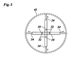
- Fig. 5 shows an application of the transmission.
- Fig. 5 shows a gear arrangement with a plurality of transmissions according to the invention, which are arranged in a circle about a central axis, which is parallel to the respective first push rod 32.
- the second push rods 34 show radially outward.
- a thrust in Fig. 1 perpendicular to the drawing plane, is exerted on the first push rods 32, the second push rods 34 generate radially outward forces with which, for example, a tube 42 can be clamped from the inside out. In this case, there is automatically a centering of the gear arrangement in the tube 42.
Landscapes
- Engineering & Computer Science (AREA)
- General Engineering & Computer Science (AREA)
- Mechanical Engineering (AREA)
- Transmission Devices (AREA)
Claims (4)
- Engrenage destiné à transmettre des forces linéaires, comportant :- au moins une première bielle (32) pour transmettre des forces linéaires dans une première direction, laquelle première bielle (32) forme un premier entraînement ou organe d'entraînement,- un balancier (12) qui est adapté pour exécuter un mouvement de bascule limité dans un plan, dans lequel le balancier (12) est guidé de manière forcée de telle sorte que lors du mouvement de bascule, un point de guidage (22) du balancier conserve une distance constante par rapport à un point (16) fixe par rapport à l'engrenage, et- au moins un second entraînement ou organe d'entraînement (34),
dans lequel le balancier (12) a un contour extérieur convexe en forme de segment circulaire (20) ayant un rayon R, au moyen duquel il est guidé dans un contour de guidage concave (14) qui est en forme de segment circulaire avec un rayon 2R,
dans lequel le contour extérieur (20) du balancier (12) et le contour de guidage (40) comportent chacun des dents (24 ; 18) qui s'engrènent les unes avec les autres,
dans lequel la première bielle (32) et le second entraînement ou organe d'entraînement (34) sont chacun reliés au balancier (12) de manière articulée, et
dans lequel la première bielle (32) est reliée au balancier (12) en un premier point d'articulation (28), lequel point d'articulation (28) exécute un mouvement de va-et-vient linéaire parallèlement au plan cité lors du mouvement de bascule du balancier (12),
caractérisé
en ce que la première bielle (32) est reliée au balancier (12) de manière articulée pour transmettre des forces de traction et de compression, et
en ce que le balancier (12) est guidé de manière forcée- au moyen d'un bras oscillant (26), lequel bras oscillant (26) peut pivoter autour du point de guidage (22) et peut pivoter autour d'un axe passant par le point (16) fixe par rapport à l'engrenage,
ou- au moyen d'un organe de roulement (36), lequel organe de roulement est monté sur le balancier (12) de manière à pouvoir tourner autour d'un axe passant par le point de guidage (22) et roule sur une glissière de guidage (38) avant le point (16) cité fixe par rapport à l'engrenage. - Engrenage selon la revendication 1, dans lequel une seconde bielle (34) forme un second entraînement ou organe d'entraînement, laquelle seconde bielle (34) est reliée au balancier (12) en un second point d'articulation (30) différent du premier point d'articulation (28), lequel second point d'articulation exécute un mouvement en va-et-vient linéaire parallèlement au plan cité lors du mouvement de bascule du balancier (12).
- Engrenage selon la revendication 1 ou 2, dans lequel le bras oscillant (26) forme une manivelle avec un mécanisme à manivelle et bielle oscillante (40), dont l'axe passe par le point (16) fixe par rapport à l'engrenage et est agencé perpendiculairement au plan cité.
- Engrenage selon l'une quelconque des revendications précédentes, dans lequel le balancier (12) est guidé de manière forcée de telle sorte que lors du mouvement de bascule, un point de guidage (22) du balancier conserve une distance constante par rapport à un point fixe par rapport à l'engrenage aussi bien lors de la transmission de forces de traction que lors de la transmission de forces de compression par l'intermédiaire de la première bielle (32).
Applications Claiming Priority (1)
| Application Number | Priority Date | Filing Date | Title |
|---|---|---|---|
| DE102008054049A DE102008054049B4 (de) | 2008-10-30 | 2008-10-30 | Getriebe |
Publications (2)
| Publication Number | Publication Date |
|---|---|
| EP2182249A1 EP2182249A1 (fr) | 2010-05-05 |
| EP2182249B1 true EP2182249B1 (fr) | 2011-12-07 |
Family
ID=41467282
Family Applications (1)
| Application Number | Title | Priority Date | Filing Date |
|---|---|---|---|
| EP09013620A Not-in-force EP2182249B1 (fr) | 2008-10-30 | 2009-10-29 | Engrenage |
Country Status (3)
| Country | Link |
|---|---|
| EP (1) | EP2182249B1 (fr) |
| AT (1) | ATE536500T1 (fr) |
| DE (1) | DE102008054049B4 (fr) |
Families Citing this family (1)
| Publication number | Priority date | Publication date | Assignee | Title |
|---|---|---|---|---|
| DE102014105457A1 (de) | 2014-04-16 | 2015-10-22 | Ewm Eichelhardter Werkzeug- Und Maschinenbau Gmbh | Mähmesserantrieb |
Family Cites Families (5)
| Publication number | Priority date | Publication date | Assignee | Title |
|---|---|---|---|---|
| US2047061A (en) * | 1931-10-10 | 1936-07-07 | Packard Motor Car Co | Valve actuating mechanism |
| US3684237A (en) * | 1970-05-04 | 1972-08-15 | Westinghouse Electric Corp | Variable force angle linkage |
| CH596539A5 (fr) * | 1977-01-06 | 1978-04-14 | Tesa Sa | |
| FR2379718A1 (fr) | 1977-02-04 | 1978-09-01 | Creusot Loire | Mecanisme de commande de va-et-vient |
| SK932004A3 (sk) * | 2004-02-10 | 2005-11-03 | Štefan Kanozsay | Dvojtaktný piestový spaľovací motor s vysokou účinnosťou pracujúci bez vibrácií |
-
2008
- 2008-10-30 DE DE102008054049A patent/DE102008054049B4/de not_active Expired - Fee Related
-
2009
- 2009-10-29 EP EP09013620A patent/EP2182249B1/fr not_active Not-in-force
- 2009-10-29 AT AT09013620T patent/ATE536500T1/de active
Also Published As
| Publication number | Publication date |
|---|---|
| ATE536500T1 (de) | 2011-12-15 |
| DE102008054049B4 (de) | 2010-08-12 |
| EP2182249A1 (fr) | 2010-05-05 |
| DE102008054049A1 (de) | 2010-05-20 |
Similar Documents
| Publication | Publication Date | Title |
|---|---|---|
| EP3117060B1 (fr) | Bras de commande pour un abattant de meuble | |
| EP2841667B1 (fr) | Entrainement pour porte pivotante | |
| EP0207251B1 (fr) | Ferme-porte | |
| EP0894573B1 (fr) | Dispositif de serrage d'une pièce | |
| DE3330204C2 (de) | Stirnradgetriebe für den Antrieb eines Walzenmantels | |
| DE10053690A1 (de) | Presse mit Linearschlitten | |
| DE10309030B3 (de) | Kniehebelpresse | |
| EP3205801B1 (fr) | Dispositif d'entraînement de porte de véhicule | |
| EP0370258A2 (fr) | Installation pour entraîner en oscillation au moins un arbre et dispositif pour avancer pas à pas une pièce à l'aide de cette installation | |
| EP2182249B1 (fr) | Engrenage | |
| DE102005007205B3 (de) | Elektromotorischer Linearantrieb | |
| EP1853136B1 (fr) | Meuble reglable servant de siege | |
| WO2006094473A1 (fr) | Dispositif pour actionner un embrayage | |
| DE3818691C2 (de) | Nähgutvorschubvorrichtung für eine Nähmaschine | |
| DE102007039303B4 (de) | Anordnung zum Betätigen einer Kupplung eines Fahrzeuges | |
| DE2553335A1 (de) | Vorrichtung zum umwandeln der kontinuierlichen drehbewegung einer antriebswelle in eine schwenkbewegung einer abtriebswelle | |
| EP3091246B1 (fr) | Frein à disque | |
| DE69216242T2 (de) | Antrieb mit variabler drehzahl, insbesondere für fahrzeuge | |
| DE10117780B4 (de) | System zur Betätigung eines Schaltgestänges einer beweglichen Baueinheit in einer gesteuerten Kupplungsvorrichtung | |
| EP1130286B1 (fr) | Mécanisme d'entrainement | |
| WO2021063808A1 (fr) | Appareil d'actionnement de soupape et raccord haute pression | |
| DE2911424C2 (de) | Ein-Zahn-Ge triebe | |
| DE10022593B4 (de) | Stelleinrichtung mit Planetengetriebe für eine hydrostatische Axialkolbenmaschine | |
| EP2906404B1 (fr) | Unité de fermeture pour une machine de moulage par injection à deux plateaux | |
| WO2013004228A1 (fr) | Dispositif d'actionnement |
Legal Events
| Date | Code | Title | Description |
|---|---|---|---|
| PUAI | Public reference made under article 153(3) epc to a published international application that has entered the european phase |
Free format text: ORIGINAL CODE: 0009012 |
|
| AK | Designated contracting states |
Kind code of ref document: A1 Designated state(s): AT BE BG CH CY CZ DE DK EE ES FI FR GB GR HR HU IE IS IT LI LT LU LV MC MK MT NL NO PL PT RO SE SI SK SM TR |
|
| AX | Request for extension of the european patent |
Extension state: AL BA RS |
|
| 17P | Request for examination filed |
Effective date: 20101029 |
|
| 17Q | First examination report despatched |
Effective date: 20101210 |
|
| GRAP | Despatch of communication of intention to grant a patent |
Free format text: ORIGINAL CODE: EPIDOSNIGR1 |
|
| RIC1 | Information provided on ipc code assigned before grant |
Ipc: B25B 5/14 20060101ALI20110406BHEP Ipc: F16H 21/44 20060101AFI20110406BHEP |
|
| GRAS | Grant fee paid |
Free format text: ORIGINAL CODE: EPIDOSNIGR3 |
|
| GRAA | (expected) grant |
Free format text: ORIGINAL CODE: 0009210 |
|
| AK | Designated contracting states |
Kind code of ref document: B1 Designated state(s): AT BE BG CH CY CZ DE DK EE ES FI FR GB GR HR HU IE IS IT LI LT LU LV MC MK MT NL NO PL PT RO SE SI SK SM TR |
|
| REG | Reference to a national code |
Ref country code: GB Ref legal event code: FG4D Free format text: NOT ENGLISH |
|
| REG | Reference to a national code |
Ref country code: CH Ref legal event code: EP |
|
| REG | Reference to a national code |
Ref country code: IE Ref legal event code: FG4D Free format text: LANGUAGE OF EP DOCUMENT: GERMAN |
|
| REG | Reference to a national code |
Ref country code: DE Ref legal event code: R096 Ref document number: 502009002107 Country of ref document: DE Effective date: 20120209 |
|
| REG | Reference to a national code |
Ref country code: NL Ref legal event code: VDEP Effective date: 20111207 |
|
| PG25 | Lapsed in a contracting state [announced via postgrant information from national office to epo] |
Ref country code: LT Free format text: LAPSE BECAUSE OF FAILURE TO SUBMIT A TRANSLATION OF THE DESCRIPTION OR TO PAY THE FEE WITHIN THE PRESCRIBED TIME-LIMIT Effective date: 20111207 Ref country code: NO Free format text: LAPSE BECAUSE OF FAILURE TO SUBMIT A TRANSLATION OF THE DESCRIPTION OR TO PAY THE FEE WITHIN THE PRESCRIBED TIME-LIMIT Effective date: 20120307 |
|
| LTIE | Lt: invalidation of european patent or patent extension |
Effective date: 20111207 |
|
| PG25 | Lapsed in a contracting state [announced via postgrant information from national office to epo] |
Ref country code: HR Free format text: LAPSE BECAUSE OF FAILURE TO SUBMIT A TRANSLATION OF THE DESCRIPTION OR TO PAY THE FEE WITHIN THE PRESCRIBED TIME-LIMIT Effective date: 20111207 Ref country code: SI Free format text: LAPSE BECAUSE OF FAILURE TO SUBMIT A TRANSLATION OF THE DESCRIPTION OR TO PAY THE FEE WITHIN THE PRESCRIBED TIME-LIMIT Effective date: 20111207 Ref country code: GR Free format text: LAPSE BECAUSE OF FAILURE TO SUBMIT A TRANSLATION OF THE DESCRIPTION OR TO PAY THE FEE WITHIN THE PRESCRIBED TIME-LIMIT Effective date: 20120308 Ref country code: SE Free format text: LAPSE BECAUSE OF FAILURE TO SUBMIT A TRANSLATION OF THE DESCRIPTION OR TO PAY THE FEE WITHIN THE PRESCRIBED TIME-LIMIT Effective date: 20111207 Ref country code: NL Free format text: LAPSE BECAUSE OF FAILURE TO SUBMIT A TRANSLATION OF THE DESCRIPTION OR TO PAY THE FEE WITHIN THE PRESCRIBED TIME-LIMIT Effective date: 20111207 Ref country code: LV Free format text: LAPSE BECAUSE OF FAILURE TO SUBMIT A TRANSLATION OF THE DESCRIPTION OR TO PAY THE FEE WITHIN THE PRESCRIBED TIME-LIMIT Effective date: 20111207 |
|
| PG25 | Lapsed in a contracting state [announced via postgrant information from national office to epo] |
Ref country code: CY Free format text: LAPSE BECAUSE OF FAILURE TO SUBMIT A TRANSLATION OF THE DESCRIPTION OR TO PAY THE FEE WITHIN THE PRESCRIBED TIME-LIMIT Effective date: 20111207 |
|
| REG | Reference to a national code |
Ref country code: IE Ref legal event code: FD4D |
|
| PG25 | Lapsed in a contracting state [announced via postgrant information from national office to epo] |
Ref country code: EE Free format text: LAPSE BECAUSE OF FAILURE TO SUBMIT A TRANSLATION OF THE DESCRIPTION OR TO PAY THE FEE WITHIN THE PRESCRIBED TIME-LIMIT Effective date: 20111207 Ref country code: SK Free format text: LAPSE BECAUSE OF FAILURE TO SUBMIT A TRANSLATION OF THE DESCRIPTION OR TO PAY THE FEE WITHIN THE PRESCRIBED TIME-LIMIT Effective date: 20111207 Ref country code: IE Free format text: LAPSE BECAUSE OF FAILURE TO SUBMIT A TRANSLATION OF THE DESCRIPTION OR TO PAY THE FEE WITHIN THE PRESCRIBED TIME-LIMIT Effective date: 20111207 Ref country code: IS Free format text: LAPSE BECAUSE OF FAILURE TO SUBMIT A TRANSLATION OF THE DESCRIPTION OR TO PAY THE FEE WITHIN THE PRESCRIBED TIME-LIMIT Effective date: 20120407 Ref country code: CZ Free format text: LAPSE BECAUSE OF FAILURE TO SUBMIT A TRANSLATION OF THE DESCRIPTION OR TO PAY THE FEE WITHIN THE PRESCRIBED TIME-LIMIT Effective date: 20111207 Ref country code: BG Free format text: LAPSE BECAUSE OF FAILURE TO SUBMIT A TRANSLATION OF THE DESCRIPTION OR TO PAY THE FEE WITHIN THE PRESCRIBED TIME-LIMIT Effective date: 20120307 |
|
| PG25 | Lapsed in a contracting state [announced via postgrant information from national office to epo] |
Ref country code: PT Free format text: LAPSE BECAUSE OF FAILURE TO SUBMIT A TRANSLATION OF THE DESCRIPTION OR TO PAY THE FEE WITHIN THE PRESCRIBED TIME-LIMIT Effective date: 20120409 Ref country code: PL Free format text: LAPSE BECAUSE OF FAILURE TO SUBMIT A TRANSLATION OF THE DESCRIPTION OR TO PAY THE FEE WITHIN THE PRESCRIBED TIME-LIMIT Effective date: 20111207 Ref country code: RO Free format text: LAPSE BECAUSE OF FAILURE TO SUBMIT A TRANSLATION OF THE DESCRIPTION OR TO PAY THE FEE WITHIN THE PRESCRIBED TIME-LIMIT Effective date: 20111207 |
|
| PLBE | No opposition filed within time limit |
Free format text: ORIGINAL CODE: 0009261 |
|
| STAA | Information on the status of an ep patent application or granted ep patent |
Free format text: STATUS: NO OPPOSITION FILED WITHIN TIME LIMIT |
|
| PG25 | Lapsed in a contracting state [announced via postgrant information from national office to epo] |
Ref country code: DK Free format text: LAPSE BECAUSE OF FAILURE TO SUBMIT A TRANSLATION OF THE DESCRIPTION OR TO PAY THE FEE WITHIN THE PRESCRIBED TIME-LIMIT Effective date: 20111207 |
|
| 26N | No opposition filed |
Effective date: 20120910 |
|
| PG25 | Lapsed in a contracting state [announced via postgrant information from national office to epo] |
Ref country code: IT Free format text: LAPSE BECAUSE OF FAILURE TO SUBMIT A TRANSLATION OF THE DESCRIPTION OR TO PAY THE FEE WITHIN THE PRESCRIBED TIME-LIMIT Effective date: 20111207 |
|
| REG | Reference to a national code |
Ref country code: DE Ref legal event code: R097 Ref document number: 502009002107 Country of ref document: DE Effective date: 20120910 |
|
| BERE | Be: lapsed |
Owner name: HELLKUHL, LUDGER Effective date: 20121031 |
|
| PG25 | Lapsed in a contracting state [announced via postgrant information from national office to epo] |
Ref country code: ES Free format text: LAPSE BECAUSE OF FAILURE TO SUBMIT A TRANSLATION OF THE DESCRIPTION OR TO PAY THE FEE WITHIN THE PRESCRIBED TIME-LIMIT Effective date: 20120318 |
|
| PG25 | Lapsed in a contracting state [announced via postgrant information from national office to epo] |
Ref country code: MC Free format text: LAPSE BECAUSE OF NON-PAYMENT OF DUE FEES Effective date: 20121031 |
|
| PG25 | Lapsed in a contracting state [announced via postgrant information from national office to epo] |
Ref country code: FI Free format text: LAPSE BECAUSE OF FAILURE TO SUBMIT A TRANSLATION OF THE DESCRIPTION OR TO PAY THE FEE WITHIN THE PRESCRIBED TIME-LIMIT Effective date: 20111207 |
|
| PG25 | Lapsed in a contracting state [announced via postgrant information from national office to epo] |
Ref country code: BE Free format text: LAPSE BECAUSE OF NON-PAYMENT OF DUE FEES Effective date: 20121031 |
|
| PG25 | Lapsed in a contracting state [announced via postgrant information from national office to epo] |
Ref country code: MT Free format text: LAPSE BECAUSE OF FAILURE TO SUBMIT A TRANSLATION OF THE DESCRIPTION OR TO PAY THE FEE WITHIN THE PRESCRIBED TIME-LIMIT Effective date: 20111207 |
|
| PG25 | Lapsed in a contracting state [announced via postgrant information from national office to epo] |
Ref country code: TR Free format text: LAPSE BECAUSE OF FAILURE TO SUBMIT A TRANSLATION OF THE DESCRIPTION OR TO PAY THE FEE WITHIN THE PRESCRIBED TIME-LIMIT Effective date: 20111207 |
|
| PG25 | Lapsed in a contracting state [announced via postgrant information from national office to epo] |
Ref country code: LU Free format text: LAPSE BECAUSE OF NON-PAYMENT OF DUE FEES Effective date: 20121029 Ref country code: SM Free format text: LAPSE BECAUSE OF FAILURE TO SUBMIT A TRANSLATION OF THE DESCRIPTION OR TO PAY THE FEE WITHIN THE PRESCRIBED TIME-LIMIT Effective date: 20111207 |
|
| REG | Reference to a national code |
Ref country code: CH Ref legal event code: PL |
|
| PG25 | Lapsed in a contracting state [announced via postgrant information from national office to epo] |
Ref country code: LI Free format text: LAPSE BECAUSE OF NON-PAYMENT OF DUE FEES Effective date: 20131031 Ref country code: HU Free format text: LAPSE BECAUSE OF FAILURE TO SUBMIT A TRANSLATION OF THE DESCRIPTION OR TO PAY THE FEE WITHIN THE PRESCRIBED TIME-LIMIT Effective date: 20091029 Ref country code: CH Free format text: LAPSE BECAUSE OF NON-PAYMENT OF DUE FEES Effective date: 20131031 |
|
| REG | Reference to a national code |
Ref country code: DE Ref legal event code: R082 Ref document number: 502009002107 Country of ref document: DE Representative=s name: NEUMANN MUELLER OBERWALLENEY & PARTNER PATENTA, DE |
|
| REG | Reference to a national code |
Ref country code: DE Ref legal event code: R082 Ref document number: 502009002107 Country of ref document: DE Representative=s name: NEUMANN MUELLER OBERWALLENEY & PARTNER PATENTA, DE |
|
| REG | Reference to a national code |
Ref country code: DE Ref legal event code: R082 Ref document number: 502009002107 Country of ref document: DE Representative=s name: NEUMANN MUELLER OBERWALLENEY & PARTNER PATENTA, DE Effective date: 20140805 Ref country code: DE Ref legal event code: R081 Ref document number: 502009002107 Country of ref document: DE Owner name: EICHELHARDTER WERKZEUG- UND MASCHINENBAU GMBH, DE Free format text: FORMER OWNER: HELLKUHL, LUDGER, 33332 GUETERSLOH, DE Effective date: 20150303 Ref country code: DE Ref legal event code: R082 Ref document number: 502009002107 Country of ref document: DE Representative=s name: NEUMANN MUELLER OBERWALLENEY & PARTNER PATENTA, DE Effective date: 20150303 Ref country code: DE Ref legal event code: R081 Ref document number: 502009002107 Country of ref document: DE Owner name: EWM EICHELHARDTER WERKZEUG- UND MASCHINENBAU G, DE Free format text: FORMER OWNER: HELLKUHL, LUDGER, 33332 GUETERSLOH, DE Effective date: 20150303 |
|
| PG25 | Lapsed in a contracting state [announced via postgrant information from national office to epo] |
Ref country code: MK Free format text: LAPSE BECAUSE OF FAILURE TO SUBMIT A TRANSLATION OF THE DESCRIPTION OR TO PAY THE FEE WITHIN THE PRESCRIBED TIME-LIMIT Effective date: 20111207 |
|
| REG | Reference to a national code |
Ref country code: GB Ref legal event code: 732E Free format text: REGISTERED BETWEEN 20150903 AND 20150909 |
|
| REG | Reference to a national code |
Ref country code: FR Ref legal event code: PLFP Year of fee payment: 7 |
|
| REG | Reference to a national code |
Ref country code: DE Ref legal event code: R082 Ref document number: 502009002107 Country of ref document: DE Representative=s name: NEUMANN MUELLER OBERWALLENEY & PARTNER PATENTA, DE Ref country code: DE Ref legal event code: R081 Ref document number: 502009002107 Country of ref document: DE Owner name: EWM EICHELHARDTER WERKZEUG- UND MASCHINENBAU G, DE Free format text: FORMER OWNER: EICHELHARDTER WERKZEUG- UND MASCHINENBAU GMBH, 57612 EICHELHARDT, DE |
|
| REG | Reference to a national code |
Ref country code: FR Ref legal event code: TP Owner name: EWM EICHELHARDTER WERKZEUG- UND MASHINENBAU GM, DE Effective date: 20151126 |
|
| REG | Reference to a national code |
Ref country code: AT Ref legal event code: PC Ref document number: 536500 Country of ref document: AT Kind code of ref document: T Owner name: EWM EICHELHARDTER WERKZEUG- UND MASCHINENBAU G, DE Effective date: 20160225 |
|
| REG | Reference to a national code |
Ref country code: FR Ref legal event code: PLFP Year of fee payment: 8 |
|
| REG | Reference to a national code |
Ref country code: FR Ref legal event code: PLFP Year of fee payment: 9 |
|
| REG | Reference to a national code |
Ref country code: FR Ref legal event code: PLFP Year of fee payment: 10 |
|
| PGFP | Annual fee paid to national office [announced via postgrant information from national office to epo] |
Ref country code: GB Payment date: 20211022 Year of fee payment: 13 Ref country code: AT Payment date: 20211019 Year of fee payment: 13 Ref country code: DE Payment date: 20211020 Year of fee payment: 13 |
|
| PGFP | Annual fee paid to national office [announced via postgrant information from national office to epo] |
Ref country code: FR Payment date: 20211021 Year of fee payment: 13 |
|
| REG | Reference to a national code |
Ref country code: DE Ref legal event code: R119 Ref document number: 502009002107 Country of ref document: DE |
|
| REG | Reference to a national code |
Ref country code: AT Ref legal event code: MM01 Ref document number: 536500 Country of ref document: AT Kind code of ref document: T Effective date: 20221029 |
|
| GBPC | Gb: european patent ceased through non-payment of renewal fee |
Effective date: 20221029 |
|
| PG25 | Lapsed in a contracting state [announced via postgrant information from national office to epo] |
Ref country code: FR Free format text: LAPSE BECAUSE OF NON-PAYMENT OF DUE FEES Effective date: 20221031 Ref country code: DE Free format text: LAPSE BECAUSE OF NON-PAYMENT OF DUE FEES Effective date: 20230503 Ref country code: AT Free format text: LAPSE BECAUSE OF NON-PAYMENT OF DUE FEES Effective date: 20221029 |
|
| PG25 | Lapsed in a contracting state [announced via postgrant information from national office to epo] |
Ref country code: GB Free format text: LAPSE BECAUSE OF NON-PAYMENT OF DUE FEES Effective date: 20221029 |