EP2182250A2 - Antriebsstrang - Google Patents
Antriebsstrang Download PDFInfo
- Publication number
- EP2182250A2 EP2182250A2 EP09169890A EP09169890A EP2182250A2 EP 2182250 A2 EP2182250 A2 EP 2182250A2 EP 09169890 A EP09169890 A EP 09169890A EP 09169890 A EP09169890 A EP 09169890A EP 2182250 A2 EP2182250 A2 EP 2182250A2
- Authority
- EP
- European Patent Office
- Prior art keywords
- combustion engine
- internal combustion
- drive train
- automatic transmission
- planetary gear
- Prior art date
- Legal status (The legal status is an assumption and is not a legal conclusion. Google has not performed a legal analysis and makes no representation as to the accuracy of the status listed.)
- Withdrawn
Links
Images

Classifications
-
- B—PERFORMING OPERATIONS; TRANSPORTING
- B60—VEHICLES IN GENERAL
- B60W—CONJOINT CONTROL OF VEHICLE SUB-UNITS OF DIFFERENT TYPE OR DIFFERENT FUNCTION; CONTROL SYSTEMS SPECIALLY ADAPTED FOR HYBRID VEHICLES; ROAD VEHICLE DRIVE CONTROL SYSTEMS FOR PURPOSES NOT RELATED TO THE CONTROL OF A PARTICULAR SUB-UNIT
- B60W20/00—Control systems specially adapted for hybrid vehicles
-
- B—PERFORMING OPERATIONS; TRANSPORTING
- B60—VEHICLES IN GENERAL
- B60K—ARRANGEMENT OR MOUNTING OF PROPULSION UNITS OR OF TRANSMISSIONS IN VEHICLES; ARRANGEMENT OR MOUNTING OF PLURAL DIVERSE PRIME-MOVERS IN VEHICLES; AUXILIARY DRIVES FOR VEHICLES; INSTRUMENTATION OR DASHBOARDS FOR VEHICLES; ARRANGEMENTS IN CONNECTION WITH COOLING, AIR INTAKE, GAS EXHAUST OR FUEL SUPPLY OF PROPULSION UNITS IN VEHICLES
- B60K6/00—Arrangement or mounting of plural diverse prime-movers for mutual or common propulsion, e.g. hybrid propulsion systems comprising electric motors and internal combustion engines
- B60K6/20—Arrangement or mounting of plural diverse prime-movers for mutual or common propulsion, e.g. hybrid propulsion systems comprising electric motors and internal combustion engines the prime-movers consisting of electric motors and internal combustion engines, e.g. HEVs
- B60K6/22—Arrangement or mounting of plural diverse prime-movers for mutual or common propulsion, e.g. hybrid propulsion systems comprising electric motors and internal combustion engines the prime-movers consisting of electric motors and internal combustion engines, e.g. HEVs characterised by apparatus, components or means specially adapted for HEVs
- B60K6/36—Arrangement or mounting of plural diverse prime-movers for mutual or common propulsion, e.g. hybrid propulsion systems comprising electric motors and internal combustion engines the prime-movers consisting of electric motors and internal combustion engines, e.g. HEVs characterised by apparatus, components or means specially adapted for HEVs characterised by the transmission gearings
- B60K6/365—Arrangement or mounting of plural diverse prime-movers for mutual or common propulsion, e.g. hybrid propulsion systems comprising electric motors and internal combustion engines the prime-movers consisting of electric motors and internal combustion engines, e.g. HEVs characterised by apparatus, components or means specially adapted for HEVs characterised by the transmission gearings with the gears having orbital motion
-
- B—PERFORMING OPERATIONS; TRANSPORTING
- B60—VEHICLES IN GENERAL
- B60K—ARRANGEMENT OR MOUNTING OF PROPULSION UNITS OR OF TRANSMISSIONS IN VEHICLES; ARRANGEMENT OR MOUNTING OF PLURAL DIVERSE PRIME-MOVERS IN VEHICLES; AUXILIARY DRIVES FOR VEHICLES; INSTRUMENTATION OR DASHBOARDS FOR VEHICLES; ARRANGEMENTS IN CONNECTION WITH COOLING, AIR INTAKE, GAS EXHAUST OR FUEL SUPPLY OF PROPULSION UNITS IN VEHICLES
- B60K6/00—Arrangement or mounting of plural diverse prime-movers for mutual or common propulsion, e.g. hybrid propulsion systems comprising electric motors and internal combustion engines
- B60K6/20—Arrangement or mounting of plural diverse prime-movers for mutual or common propulsion, e.g. hybrid propulsion systems comprising electric motors and internal combustion engines the prime-movers consisting of electric motors and internal combustion engines, e.g. HEVs
- B60K6/22—Arrangement or mounting of plural diverse prime-movers for mutual or common propulsion, e.g. hybrid propulsion systems comprising electric motors and internal combustion engines the prime-movers consisting of electric motors and internal combustion engines, e.g. HEVs characterised by apparatus, components or means specially adapted for HEVs
- B60K6/38—Arrangement or mounting of plural diverse prime-movers for mutual or common propulsion, e.g. hybrid propulsion systems comprising electric motors and internal combustion engines the prime-movers consisting of electric motors and internal combustion engines, e.g. HEVs characterised by apparatus, components or means specially adapted for HEVs characterised by the driveline clutches
- B60K6/387—Actuated clutches, i.e. clutches engaged or disengaged by electric, hydraulic or mechanical actuating means
-
- B—PERFORMING OPERATIONS; TRANSPORTING
- B60—VEHICLES IN GENERAL
- B60K—ARRANGEMENT OR MOUNTING OF PROPULSION UNITS OR OF TRANSMISSIONS IN VEHICLES; ARRANGEMENT OR MOUNTING OF PLURAL DIVERSE PRIME-MOVERS IN VEHICLES; AUXILIARY DRIVES FOR VEHICLES; INSTRUMENTATION OR DASHBOARDS FOR VEHICLES; ARRANGEMENTS IN CONNECTION WITH COOLING, AIR INTAKE, GAS EXHAUST OR FUEL SUPPLY OF PROPULSION UNITS IN VEHICLES
- B60K6/00—Arrangement or mounting of plural diverse prime-movers for mutual or common propulsion, e.g. hybrid propulsion systems comprising electric motors and internal combustion engines
- B60K6/20—Arrangement or mounting of plural diverse prime-movers for mutual or common propulsion, e.g. hybrid propulsion systems comprising electric motors and internal combustion engines the prime-movers consisting of electric motors and internal combustion engines, e.g. HEVs
- B60K6/42—Arrangement or mounting of plural diverse prime-movers for mutual or common propulsion, e.g. hybrid propulsion systems comprising electric motors and internal combustion engines the prime-movers consisting of electric motors and internal combustion engines, e.g. HEVs characterised by the architecture of the hybrid electric vehicle
- B60K6/48—Parallel type
-
- B—PERFORMING OPERATIONS; TRANSPORTING
- B60—VEHICLES IN GENERAL
- B60K—ARRANGEMENT OR MOUNTING OF PROPULSION UNITS OR OF TRANSMISSIONS IN VEHICLES; ARRANGEMENT OR MOUNTING OF PLURAL DIVERSE PRIME-MOVERS IN VEHICLES; AUXILIARY DRIVES FOR VEHICLES; INSTRUMENTATION OR DASHBOARDS FOR VEHICLES; ARRANGEMENTS IN CONNECTION WITH COOLING, AIR INTAKE, GAS EXHAUST OR FUEL SUPPLY OF PROPULSION UNITS IN VEHICLES
- B60K6/00—Arrangement or mounting of plural diverse prime-movers for mutual or common propulsion, e.g. hybrid propulsion systems comprising electric motors and internal combustion engines
- B60K6/20—Arrangement or mounting of plural diverse prime-movers for mutual or common propulsion, e.g. hybrid propulsion systems comprising electric motors and internal combustion engines the prime-movers consisting of electric motors and internal combustion engines, e.g. HEVs
- B60K6/50—Architecture of the driveline characterised by arrangement or kind of transmission units
- B60K6/54—Transmission for changing ratio
- B60K6/547—Transmission for changing ratio the transmission being a stepped gearing
-
- B—PERFORMING OPERATIONS; TRANSPORTING
- B60—VEHICLES IN GENERAL
- B60W—CONJOINT CONTROL OF VEHICLE SUB-UNITS OF DIFFERENT TYPE OR DIFFERENT FUNCTION; CONTROL SYSTEMS SPECIALLY ADAPTED FOR HYBRID VEHICLES; ROAD VEHICLE DRIVE CONTROL SYSTEMS FOR PURPOSES NOT RELATED TO THE CONTROL OF A PARTICULAR SUB-UNIT
- B60W10/00—Conjoint control of vehicle sub-units of different type or different function
- B60W10/02—Conjoint control of vehicle sub-units of different type or different function including control of driveline clutches
-
- B—PERFORMING OPERATIONS; TRANSPORTING
- B60—VEHICLES IN GENERAL
- B60W—CONJOINT CONTROL OF VEHICLE SUB-UNITS OF DIFFERENT TYPE OR DIFFERENT FUNCTION; CONTROL SYSTEMS SPECIALLY ADAPTED FOR HYBRID VEHICLES; ROAD VEHICLE DRIVE CONTROL SYSTEMS FOR PURPOSES NOT RELATED TO THE CONTROL OF A PARTICULAR SUB-UNIT
- B60W10/00—Conjoint control of vehicle sub-units of different type or different function
- B60W10/04—Conjoint control of vehicle sub-units of different type or different function including control of propulsion units
- B60W10/06—Conjoint control of vehicle sub-units of different type or different function including control of propulsion units including control of combustion engines
-
- B—PERFORMING OPERATIONS; TRANSPORTING
- B60—VEHICLES IN GENERAL
- B60W—CONJOINT CONTROL OF VEHICLE SUB-UNITS OF DIFFERENT TYPE OR DIFFERENT FUNCTION; CONTROL SYSTEMS SPECIALLY ADAPTED FOR HYBRID VEHICLES; ROAD VEHICLE DRIVE CONTROL SYSTEMS FOR PURPOSES NOT RELATED TO THE CONTROL OF A PARTICULAR SUB-UNIT
- B60W10/00—Conjoint control of vehicle sub-units of different type or different function
- B60W10/04—Conjoint control of vehicle sub-units of different type or different function including control of propulsion units
- B60W10/08—Conjoint control of vehicle sub-units of different type or different function including control of propulsion units including control of electric propulsion units, e.g. motors or generators
-
- B—PERFORMING OPERATIONS; TRANSPORTING
- B60—VEHICLES IN GENERAL
- B60W—CONJOINT CONTROL OF VEHICLE SUB-UNITS OF DIFFERENT TYPE OR DIFFERENT FUNCTION; CONTROL SYSTEMS SPECIALLY ADAPTED FOR HYBRID VEHICLES; ROAD VEHICLE DRIVE CONTROL SYSTEMS FOR PURPOSES NOT RELATED TO THE CONTROL OF A PARTICULAR SUB-UNIT
- B60W10/00—Conjoint control of vehicle sub-units of different type or different function
- B60W10/10—Conjoint control of vehicle sub-units of different type or different function including control of change-speed gearings
- B60W10/11—Stepped gearings
-
- B—PERFORMING OPERATIONS; TRANSPORTING
- B60—VEHICLES IN GENERAL
- B60W—CONJOINT CONTROL OF VEHICLE SUB-UNITS OF DIFFERENT TYPE OR DIFFERENT FUNCTION; CONTROL SYSTEMS SPECIALLY ADAPTED FOR HYBRID VEHICLES; ROAD VEHICLE DRIVE CONTROL SYSTEMS FOR PURPOSES NOT RELATED TO THE CONTROL OF A PARTICULAR SUB-UNIT
- B60W30/00—Purposes of road vehicle drive control systems not related to the control of a particular sub-unit, e.g. of systems using conjoint control of vehicle sub-units
- B60W30/18—Propelling the vehicle
- B60W30/18009—Propelling the vehicle related to particular drive situations
- B60W30/18027—Drive off, accelerating from standstill
-
- B—PERFORMING OPERATIONS; TRANSPORTING
- B60—VEHICLES IN GENERAL
- B60W—CONJOINT CONTROL OF VEHICLE SUB-UNITS OF DIFFERENT TYPE OR DIFFERENT FUNCTION; CONTROL SYSTEMS SPECIALLY ADAPTED FOR HYBRID VEHICLES; ROAD VEHICLE DRIVE CONTROL SYSTEMS FOR PURPOSES NOT RELATED TO THE CONTROL OF A PARTICULAR SUB-UNIT
- B60W30/00—Purposes of road vehicle drive control systems not related to the control of a particular sub-unit, e.g. of systems using conjoint control of vehicle sub-units
- B60W30/18—Propelling the vehicle
- B60W30/19—Improvement of gear change, e.g. by synchronisation or smoothing gear shift
-
- F—MECHANICAL ENGINEERING; LIGHTING; HEATING; WEAPONS; BLASTING
- F16—ENGINEERING ELEMENTS AND UNITS; GENERAL MEASURES FOR PRODUCING AND MAINTAINING EFFECTIVE FUNCTIONING OF MACHINES OR INSTALLATIONS; THERMAL INSULATION IN GENERAL
- F16H—GEARING
- F16H37/00—Combinations of mechanical gearings, not provided for in groups F16H1/00 - F16H35/00
- F16H37/02—Combinations of mechanical gearings, not provided for in groups F16H1/00 - F16H35/00 comprising essentially only toothed or friction gearings
- F16H37/06—Combinations of mechanical gearings, not provided for in groups F16H1/00 - F16H35/00 comprising essentially only toothed or friction gearings with a plurality of driving or driven shafts; with arrangements for dividing torque between two or more intermediate shafts
- F16H37/08—Combinations of mechanical gearings, not provided for in groups F16H1/00 - F16H35/00 comprising essentially only toothed or friction gearings with a plurality of driving or driven shafts; with arrangements for dividing torque between two or more intermediate shafts with differential gearing
- F16H37/0833—Combinations of mechanical gearings, not provided for in groups F16H1/00 - F16H35/00 comprising essentially only toothed or friction gearings with a plurality of driving or driven shafts; with arrangements for dividing torque between two or more intermediate shafts with differential gearing with arrangements for dividing torque between two or more intermediate shafts, i.e. with two or more internal power paths
- F16H37/084—Combinations of mechanical gearings, not provided for in groups F16H1/00 - F16H35/00 comprising essentially only toothed or friction gearings with a plurality of driving or driven shafts; with arrangements for dividing torque between two or more intermediate shafts with differential gearing with arrangements for dividing torque between two or more intermediate shafts, i.e. with two or more internal power paths at least one power path being a continuously variable transmission, i.e. CVT
-
- B—PERFORMING OPERATIONS; TRANSPORTING
- B60—VEHICLES IN GENERAL
- B60L—PROPULSION OF ELECTRICALLY-PROPELLED VEHICLES; SUPPLYING ELECTRIC POWER FOR AUXILIARY EQUIPMENT OF ELECTRICALLY-PROPELLED VEHICLES; ELECTRODYNAMIC BRAKE SYSTEMS FOR VEHICLES IN GENERAL; MAGNETIC SUSPENSION OR LEVITATION FOR VEHICLES; MONITORING OPERATING VARIABLES OF ELECTRICALLY-PROPELLED VEHICLES; ELECTRIC SAFETY DEVICES FOR ELECTRICALLY-PROPELLED VEHICLES
- B60L2240/00—Control parameters of input or output; Target parameters
- B60L2240/40—Drive Train control parameters
- B60L2240/42—Drive Train control parameters related to electric machines
- B60L2240/423—Torque
-
- B—PERFORMING OPERATIONS; TRANSPORTING
- B60—VEHICLES IN GENERAL
- B60W—CONJOINT CONTROL OF VEHICLE SUB-UNITS OF DIFFERENT TYPE OR DIFFERENT FUNCTION; CONTROL SYSTEMS SPECIALLY ADAPTED FOR HYBRID VEHICLES; ROAD VEHICLE DRIVE CONTROL SYSTEMS FOR PURPOSES NOT RELATED TO THE CONTROL OF A PARTICULAR SUB-UNIT
- B60W2710/00—Output or target parameters relating to a particular sub-units
- B60W2710/06—Combustion engines, Gas turbines
- B60W2710/0666—Engine torque
-
- B—PERFORMING OPERATIONS; TRANSPORTING
- B60—VEHICLES IN GENERAL
- B60W—CONJOINT CONTROL OF VEHICLE SUB-UNITS OF DIFFERENT TYPE OR DIFFERENT FUNCTION; CONTROL SYSTEMS SPECIALLY ADAPTED FOR HYBRID VEHICLES; ROAD VEHICLE DRIVE CONTROL SYSTEMS FOR PURPOSES NOT RELATED TO THE CONTROL OF A PARTICULAR SUB-UNIT
- B60W2710/00—Output or target parameters relating to a particular sub-units
- B60W2710/08—Electric propulsion units
- B60W2710/083—Torque
-
- F—MECHANICAL ENGINEERING; LIGHTING; HEATING; WEAPONS; BLASTING
- F02—COMBUSTION ENGINES; HOT-GAS OR COMBUSTION-PRODUCT ENGINE PLANTS
- F02D—CONTROLLING COMBUSTION ENGINES
- F02D41/00—Electrical control of supply of combustible mixture or its constituents
- F02D41/02—Circuit arrangements for generating control signals
- F02D41/021—Introducing corrections for particular conditions exterior to the engine
- F02D41/0215—Introducing corrections for particular conditions exterior to the engine in relation with elements of the transmission
-
- F—MECHANICAL ENGINEERING; LIGHTING; HEATING; WEAPONS; BLASTING
- F02—COMBUSTION ENGINES; HOT-GAS OR COMBUSTION-PRODUCT ENGINE PLANTS
- F02N—STARTING OF COMBUSTION ENGINES; STARTING AIDS FOR SUCH ENGINES, NOT OTHERWISE PROVIDED FOR
- F02N11/00—Starting of engines by means of electric motors
- F02N11/08—Circuits specially adapted for starting of engines
- F02N11/0814—Circuits specially adapted for starting of engines comprising means for controlling automatic idle-start-stop
- F02N11/0818—Conditions for starting or stopping the engine or for deactivating the idle-start-stop mode
- F02N11/0822—Conditions for starting or stopping the engine or for deactivating the idle-start-stop mode related to action of the driver
-
- F—MECHANICAL ENGINEERING; LIGHTING; HEATING; WEAPONS; BLASTING
- F16—ENGINEERING ELEMENTS AND UNITS; GENERAL MEASURES FOR PRODUCING AND MAINTAINING EFFECTIVE FUNCTIONING OF MACHINES OR INSTALLATIONS; THERMAL INSULATION IN GENERAL
- F16H—GEARING
- F16H61/00—Control functions within control units of change-speed- or reversing-gearings for conveying rotary motion ; Control of exclusively fluid gearing, friction gearing, gearings with endless flexible members or other particular types of gearing
- F16H61/04—Smoothing ratio shift
- F16H2061/0425—Bridging torque interruption
- F16H2061/0433—Bridging torque interruption by torque supply with an electric motor
-
- F—MECHANICAL ENGINEERING; LIGHTING; HEATING; WEAPONS; BLASTING
- F16—ENGINEERING ELEMENTS AND UNITS; GENERAL MEASURES FOR PRODUCING AND MAINTAINING EFFECTIVE FUNCTIONING OF MACHINES OR INSTALLATIONS; THERMAL INSULATION IN GENERAL
- F16H—GEARING
- F16H3/00—Toothed gearings for conveying rotary motion with variable gear ratio or for reversing rotary motion
- F16H3/006—Toothed gearings for conveying rotary motion with variable gear ratio or for reversing rotary motion power being selectively transmitted by parallel flow paths, e.g. dual clutch transmissions
-
- F—MECHANICAL ENGINEERING; LIGHTING; HEATING; WEAPONS; BLASTING
- F16—ENGINEERING ELEMENTS AND UNITS; GENERAL MEASURES FOR PRODUCING AND MAINTAINING EFFECTIVE FUNCTIONING OF MACHINES OR INSTALLATIONS; THERMAL INSULATION IN GENERAL
- F16H—GEARING
- F16H3/00—Toothed gearings for conveying rotary motion with variable gear ratio or for reversing rotary motion
- F16H3/44—Toothed gearings for conveying rotary motion with variable gear ratio or for reversing rotary motion using gears having orbital motion
- F16H3/72—Toothed gearings for conveying rotary motion with variable gear ratio or for reversing rotary motion using gears having orbital motion with a secondary drive, e.g. regulating motor, in order to vary speed continuously
- F16H3/724—Toothed gearings for conveying rotary motion with variable gear ratio or for reversing rotary motion using gears having orbital motion with a secondary drive, e.g. regulating motor, in order to vary speed continuously using externally powered electric machines
- F16H3/725—Toothed gearings for conveying rotary motion with variable gear ratio or for reversing rotary motion using gears having orbital motion with a secondary drive, e.g. regulating motor, in order to vary speed continuously using externally powered electric machines with means to change ratio in the mechanical gearing
-
- Y—GENERAL TAGGING OF NEW TECHNOLOGICAL DEVELOPMENTS; GENERAL TAGGING OF CROSS-SECTIONAL TECHNOLOGIES SPANNING OVER SEVERAL SECTIONS OF THE IPC; TECHNICAL SUBJECTS COVERED BY FORMER USPC CROSS-REFERENCE ART COLLECTIONS [XRACs] AND DIGESTS
- Y02—TECHNOLOGIES OR APPLICATIONS FOR MITIGATION OR ADAPTATION AGAINST CLIMATE CHANGE
- Y02T—CLIMATE CHANGE MITIGATION TECHNOLOGIES RELATED TO TRANSPORTATION
- Y02T10/00—Road transport of goods or passengers
- Y02T10/60—Other road transportation technologies with climate change mitigation effect
- Y02T10/62—Hybrid vehicles
-
- Y—GENERAL TAGGING OF NEW TECHNOLOGICAL DEVELOPMENTS; GENERAL TAGGING OF CROSS-SECTIONAL TECHNOLOGIES SPANNING OVER SEVERAL SECTIONS OF THE IPC; TECHNICAL SUBJECTS COVERED BY FORMER USPC CROSS-REFERENCE ART COLLECTIONS [XRACs] AND DIGESTS
- Y02—TECHNOLOGIES OR APPLICATIONS FOR MITIGATION OR ADAPTATION AGAINST CLIMATE CHANGE
- Y02T—CLIMATE CHANGE MITIGATION TECHNOLOGIES RELATED TO TRANSPORTATION
- Y02T10/00—Road transport of goods or passengers
- Y02T10/60—Other road transportation technologies with climate change mitigation effect
- Y02T10/64—Electric machine technologies in electromobility
Definitions
- the invention relates to a drive train of a motor vehicle comprising at least one transmission and a hybrid drive according to the preamble of claim 1.
- the main components of a drive train of a motor vehicle are a drive unit and a transmission.
- a gearbox converts torques and speeds and thus converts the tractive power of the drive unit.
- the present invention relates to a drive train comprising at least as a transmission, an automatic transmission and a drive unit as a hybrid drive with an internal combustion engine and an electric motor.
- An automatic transmission is to be understood in particular as a transmission in which gear changes are automatically performed with interruption of traction. In an automatic transmission, but it may also be a transmission in which gear changes are performed automatically without interruption of traction.
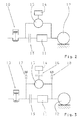
- Fig. 1 shows a known from practice powertrain scheme for a powertrain with a hybrid drive, which includes an internal combustion engine 1 and an electric motor 2.
- a transmission 3 converts the traction power supply of the hybrid drive and provides the same at an output 4 ready.
- Fig. 1 is connected between the engine 1 and the electric motor 2, a clutch 5.
- a gear-external starting element 6 is connected.
- a gear-internal starting element may be present.
- structure of a powertrain with a hybrid drive is also referred to as a parallel hybrid powertrain.
- the starting element 6 is exposed to high loads. This can lead to premature wear of the starting element. Furthermore, when a transmission is used, when the gear change is smooth, it is possible to automatically perform the traction interruption, and the gear change can not be performed while maintaining the traction at the output. There is therefore a need for a drive train with which these disadvantages can be avoided.
- the present invention is based on the problem of creating a novel drive train.
- This problem is solved by a drive train according to claim 1.
- the internal combustion engine is coupled to a transmission input of the automatic transmission, wherein the electric motor is coupled to a planetary gear, which provides a second power path parallel to a first power path provided by the automatic transmission.
- Fig. 2 shows a first embodiment of a drive train of a motor vehicle according to the invention, wherein according to Fig. 2 the powertrain has an internal combustion engine 10, a transmission 11 and an output 12.
- the internal combustion engine 10 is coupled with the interposition of a starting element 13 to the transmission input of the transmission 11, wherein it is an automatic transmission in the transmission 11.
- shifting and thus gear changes are automatically performed, in particular with traction interruption in the transmission 11.
- the transmission output of the transmission 11 is coupled to the output 12.
- the drive train has the Fig. 2 via an electric motor 14 coupled to a planetary gear 15, wherein the planetary gear 15 provides a power path that is parallel to the power path provided by the automatic transmission 11.
- the power path of the planetary gear 15 extends parallel to the automatic transmission 11 and the starting element 13th
- the electric motor 14 acts on a sun gear of the planetary gear 15.
- the internal combustion engine 10 engages a ring gear of the planetary gear 15 and the output 12 to a web of the planetary gear 15 at.
- the internal combustion engine 10 is coupled to the web of the planetary gear 15 and the output 12 is coupled to the ring gear of the planetary gear 15.
- Fig. 2 shown powertrain starting and / or shunting and / or crawling of the drive train to provide a driver-dependent output torque at the output 12 characterized in that the electric motor 14 as much as possible supported by the engine 10 torque on the planetary gear 15 and the planetary gear 15th at the output 12, whereas the starting element 13 transmits as little as possible of the torque provided by the internal combustion engine 10 and provides via the automatic transmission 11 at the output 12 so as to provide in sum the driver-request-dependent output torque at the output 12.
- a desired driver torque for the output 12 is thus determined, wherein as much as possible of this desired output torque, which is provided by the internal combustion engine 10, is provided via the power path of the planetary gear 15 on the output 12, and as little as possible this desired output torque, which is provided by the internal combustion engine 10, is provided via the power path of the automatic transmission 11 on the output 12.
- the torque which can be supported by the electric motor 14 on the planetary gear 15 and thus the torque which can be provided via the power path of the planetary gear 15 at the output 12 depends on the dimensioning of the electric motor 14 and the dimensioning of an electrical energy store of the drive train.
- the starting element 13 can also be completely opened or stay, then a schißißbuilds start, maneuvering or crawling possible is.
- a circuit or a gear change in the automatic transmission 11 can be done either with an open starting element 13 or closed starting element 13.
- a torque provided by the engine 10 is supported so as to enable a circuit without interruption of traction, by the power path of the transmission 12 even when a circuit in the automatic transmission 11 on the output 12 an output torque is provided.
- the internal combustion engine 10 reduces the torque provided by the same while supporting the moment on the planetary gear 14 so far that the starting element 13 can open without torque.
- the automatic transmission 11 then performs a gear change from an actual gear into a target gear by utilizing an internal gear synchronization, wherein then the starting element 13 closes and the engine 10 builds load and therefore increases the moment provided by the same.
- An internal transmission synchronization is also referred to as passive synchronization, which is done via internal gear synchronizers.
- a gear external synchronization is also referred to as active synchronization and takes place in that the internal combustion engine 10 and / or the electric motor 14 adjusts the torque applied to the transmission input of the automatic transmission 11 after the interpretation of the actual gear and before inserting the target gear for speed change ,
- drive train can be a so-called boost with closed start-up element 13 and when inserted in the automatic transmission 11 gear done by the electric motor 14 is operated by a motor. If, with the starting element 13 closed and the gear engaged in the automatic gearbox 11, the electric motor 14 is operated as a generator, so-called recuperation takes place.
- the starting element 13 of the Fig. 2 also omitted, in which case the power path of the planetary gear 15 in turn runs parallel to the power path of the automatic transmission 11. Also, in the event that no starting element 13 is present, so that the internal combustion engine 10 is coupled directly to the transmission input of the automatic transmission 11, the above functions can start or shunting or crawling, switching, starting the internal combustion engine, stopping the internal combustion engine, Boosting and recuperation are guaranteed.
- a shift and thus gear change in the automatic transmission 11 in a drive train without starting element 13 is analogous to that in reference to Fig. 2 described switching with closed starting element 13th
- Fig. 3 shows a further advantageous embodiment of the drive train according to the invention, wherein according to Fig. 3 between the electric motor 14 and the planetary gear 15, a clutch 16 is connected.
- a clutch 16 With the help of the separating clutch 16, it is possible to decouple the electric motor 14 from the planetary gear 15 to z. B. to avoid zero load losses.
- the electric motor 14 In the absence of clutch 16, the electric motor 14 must always rotate and depending on the stationary gear ratio of the planetary gear 15 and connection to the planetary gear 15 reach significantly higher speeds than the engine 10.
- a brake 17 acts on the second power path between the internal combustion engine 10 and the planetary gear 15, so the brake 17 acts on a crankshaft of the internal combustion engine 10.
- this brake 17 is a purely electric driving and recuperation when the internal combustion engine 10 is possible.
- the starting element 13 is then opened and the automatic transmission 11 is in neutral position.
- a brake 18 can act on the second power path between the planetary gear 15 and the output 12, wherein an active starting and an active stopping of the internal combustion engine 10 by the electric motor 14 at standstill is possible by operating the brake 18.
Landscapes
- Engineering & Computer Science (AREA)
- Mechanical Engineering (AREA)
- Chemical & Material Sciences (AREA)
- Combustion & Propulsion (AREA)
- Transportation (AREA)
- Automation & Control Theory (AREA)
- General Engineering & Computer Science (AREA)
- Arrangement Of Transmissions (AREA)
Abstract
Description
- Die Erfindung betrifft einen zumindest ein Getriebe und einen Hybridantrieb umfassenden Antriebsstrang eines Kraftfahrzeugs nach dem Oberbegriff des Anspruchs 1.
- Die Hauptkomponenten eines Antriebsstrangs eines Kraftfahrzeugs sind ein Antriebsaggregat und ein Getriebe. Ein Getriebe wandelt Drehmomente und Drehzahlen und setzt so das Zugkraftangebot des Antriebsaggregats um. Die hier vorliegende Erfindung betrifft einen Antriebsstrang, der zumindest als Getriebe ein automatisches Schaltgetriebe und als Antriebsaggregat einen Hybridantrieb mit einem Verbrennungsmotor und einem Elektromotor umfasst.
- Unter einem automatischen Schaltgetriebe soll insbesondere ein Getriebe verstanden werden, bei dem Gangwechsel automatisch mit Zugkraftunterbrechung durchgeführt werden. Bei einem automatischen Schaltgetriebe kann es sich aber auch um ein Getriebe handeln, bei dem Gangwechsel automatisch ohne Zugkraftunterbrechung durchgeführt werden.
-
Fig. 1 zeigt ein aus der Praxis bekanntes Antriebsstrangschema für einen Antriebsstrang mit einem Hybridantrieb, der einen Verbrennungsmotor 1 und einen Elektromotor 2 umfasst. Ein Getriebe 3 setzt das Zugkraftangebot des Hybridantriebs um und stellt dasselbe an einem Abtrieb 4 bereit. InFig. 1 ist zwischen den Verbrennungsmotor 1 und den Elektromotor 2 eine Kupplung 5 geschaltet. Weiterhin ist gemäßFig. 1 zwischen den Elektromotor 2 und das Getriebe 3 ein getriebeexternes Anfahrelement 6 geschaltet. Anstelle eines getriebeexternen Anfahrelements 6 kann auch ein getriebeinternes Anfahrelement vorhanden sein. Die inFig. 1 dargestellte Struktur eines Antriebsstrangs mit einem Hybridantrieb wird auch als Parallelhybrid-Antriebsstrang bezeichnet. - Bei dem in
Fig. 1 gezeigten, aus der Praxis bekannten Parallelhybrid-Antriebsstrang ist das Anfahrelement 6 hohen Belastungen ausgesetzt. Dies kann zu einem vorzeitigen Verschleiß des Anfahrelements führen. Weiterhin können dann, wenn ein Getriebe verwendet wird, bei weichem Gangwechsel automatisch mit Zugkraftunterbrechung durchgeführt werden, Gangwechsel nicht unter Erhalt der Zugkraft am Abtrieb ausgeführt werden. Es besteht daher Bedarf an einem Antriebsstrang, mit weichem diese Nachteile vermieden werden können. - Hiervon ausgehend liegt der vorliegenden Erfindung das Problem zu Grunde, einen neuartigen Antriebsstrang zu schaffen. Dieses Problem wird durch einen Antriebsstrang gemäß Anspruch 1 gelöst. Erfindungsgemäß ist der Verbrennungsmotor an einen Getriebeeingang des automatischen Schaltgetriebes gekoppelt, wobei der Elektromotor an ein Planetengetriebe gekoppelt ist, weiches parallel zu einem vom automatischen Schaltgetriebe bereitgestellten ersten Leistungspfad einen zweiten Leistungspfad bereitstellt.
- Bei dem erfindungsgemäßen Konzept für einen Antriebsstrang mit einem Hybridantrieb werden zwei Leistungspfade bereitgestellt, nämlich ein Leistungspfad über das automatische Schaltgetriebe und ein anderer Leistungspfad über das Planetengetriebe, wobei der Elektromotor des Hybridantriebs an das Planetengetriebe, nämlich an ein Sonnenrad des Planetengetriebes, gekoppelt ist. Hierdurch ist es möglich, beim Anfahren ein gegebenenfalls vorhandenes Anfahrelement zu entlasten. Gegebenenfalls kann vollständig auf ein Anfahrelement verzichtet werden. Weiterhin können selbst dann, wenn ein automatisches Schaltgetriebe verwendet wird, bei welchem Gangwechsel mit Zugkraftunterbrechung durchgeführt werden, Gangwechsel unter Aufrechterhaltung eines Moments und demnach unter Erhaltung der Zugkraft am Abtrieb ausgeführt werden. Dann, wenn der Elektromotor des Hybridantriebs und/oder ein Energiespeicher desselben ausfällt, kann der Antriebsstrang konventionell ausschließlich über den Verbrennungsmotor betrieben werden.
- Bevorzugte Weiterbildungen der Erfindung ergeben sich aus den Unteransprüchen und der nachfolgenden Beschreibung. Ausführungsbeispiele der Erfindung werden, ohne hierauf beschränkt zu sein, an Hand der Zeichnung näher erläutert. Dabei zeigt:
- Fig. 1
- ein aus der Praxis bekanntes Antriebsstrangschema eines Kraftfahrzeugs;
- Fig. 2
- ein erstes erfindungsgemäßes Antriebsstrangschema eines Kraftfahrzeugs; und
- Fig. 3
- ein zweites erfindungsgemäßes Antriebsstrangschema eines Kraftfahrzeugs.
-
Fig. 2 zeigt ein erstes Ausführungsbeispiel eines erfindungsgemäßen Antriebsstrangs eines Kraftfahrzeugs, wobei gemäßFig. 2 der Antriebsstrang einen Verbrennungsmotor 10, ein Getriebe 11 und einen Abtrieb 12 aufweist. InFig. 2 ist der Verbrennungsmotor 10 unter Zwischenschaltung eines Anfahrelements 13 an den Getriebeeingang des Getriebes 11 gekoppelt, wobei es sich beim Getriebe 11 um ein automatisches Schaltgetriebe handelt. Bei einem automatischen Schaltgetriebe werden Schaltungen und damit Gangwechsel automatisch durchgeführt, und zwar insbesondere mit Zugkraftunterbrechung im Getriebe 11. Der Getriebeausgang des Getriebes 11 ist an den Abtrieb 12 gekoppelt. - Ferner verfügt der Antriebsstrang der
Fig. 2 über einen Elektromotor 14, der an ein Planetengetriebe 15 gekoppelt ist, wobei das Planetengetriebe 15 einen Leistungspfad bereitstellt, der parallel zu dem vom automatischen Schaltgetriebe 11 bereitgestellten Leistungspfad verläuft. Dabei erstreckt sich der Leistungspfad des Planetengetriebes 15 parallel zum automatischen Schaltgetriebe 11 sowie zum Anfahrelement 13. - Der Elektromotor 14 greift an einem Sonnenrad des Planetengetriebes 15 an. Nach einer ersten Variante greift der Verbrennungsmotor 10 an einem Hohlrad des Planetengetriebes 15 und der Abtrieb 12 an einem Steg des Planetengetriebes 15 an. Nach einer zweiten Alternative ist der Verbrennungsmotor 10 an den Steg des Planetengetriebes 15 und der Abtrieb 12 an das Hohlrad des Planetengetriebes 15 gekoppelt.
- Bei dem in
Fig. 2 dargestellten Antriebsstrang erfolgt ein Anfahren und/oder ein Rangieren und/oder ein Kriechen des Antriebsstrangs unter Bereitstellung eines fahrerwunschabhängigen Abtriebsmoments am Abtrieb 12 dadurch, dass der Elektromotor 14 am Planetengetriebe 15 so viel wie möglich des vom Verbrennungsmotor 10 bereitgestellten Moments abstützt und über das Planetengetriebe 15 am Abtrieb 12 bereitstellt, wohingegen das Anfahrelement 13 so wenig wie möglich des vom Verbrennungsmotor 10 bereitgestellten Moments überträgt und über das automatische Schaltgetriebe 11 am Abtrieb 12 bereitstellt, um so in Summe das fahrerwunschabhängige Abtriebsmoment am Abtrieb 12 bereitzustellen. - Zum Anfahren und/oder Rangieren und/oder Kriechen wird demnach ein Fahrerwunschmoment für den Abtrieb 12 ermittelt, wobei so viel wie möglich dieses gewünschten Abtriebsmoments, welches vom Verbrennungsmotor 10 bereitgestellt wird, über den Leistungspfad des Planetengetriebes 15 am Abtrieb 12 bereitgestellt wird, und wobei so wenig wie möglich dieses gewünschten Abtriebsmoment, welches vom Verbrennungsmotor 10 bereitgestellt wird, über den Leistungspfad des automatischen Schaltgetriebes 11 am Abtrieb 12 bereitgestellt wird. Das vom Elektromotor 14 am Planetengetriebe 15 abstützbare Moment und damit das über den Leistungspfad des Planetengetriebes 15 am Abtrieb 12 bereitstellbare Moment ist dabei von der Dimensionierung des Elektromotors 14 sowie der Dimensionierung eines elektrischen Energiespeichers des Antriebsstrangs abhängig.
- Für den Fall, dass das fahrerwunschabhängige Abtriebsmoment beim Anfahren, Rangieren oder Kriechen vollständig über den Leistungspfad des Planetengetriebes 15 am Abtrieb 12 bereitgestellt werden kann, kann das Anfahrelement 13 auch ganz geöffnet werden bzw. bleiben, wobei dann ein verschieißfreies Anfahren, Rangieren oder Kriechen möglich ist.
- Soll bei dem in
Fig. 2 gezeigten Antriebsstrang eine Schaltung bzw. ein Gangwechsel im automatischen Schaltgetriebe 11 erfolgen, so kann dies entweder mit geöffnetem Anfahrelement 13 oder geschlossenem Anfahrelement 13 erfolgen. In jedem Fall wird zur Ausführung einer Schaltung im automatischen Schaltgetriebe 11 mit Hilfe des Elektromotors 14 am Planetengetriebe 15 ein vom Verbrennungsmotor 10 bereitgestelltes Moment abgestützt, um so einen Schaltung ohne Zugkraftunterbrechung zu ermöglichen, indem über den Leistungspfad des Getriebes 12 auch bei Ausführung einer Schaltung im automatischen Schaltgetriebe 11 am Abtrieb 12 ein Abtriebsmoment bereitgestellt wird. - Soll bei dem in
Fig. 2 gezeigten Antriebsstrang eine Schaltung im automatischen Schaltgetriebe 11 unter zumindest teilweisem Öffnen des Anfahrelements 13 erfolgen, so reduziert der Verbrennungsmotor 10 das von demselben bereitgestellte Moment bei gleichzeitiger Abstützung des Moments am Planetengetriebe 14 so weit, dass das Anfahrelement 13 momentfrei öffnen kann. Das automatische Schaltgetriebe 11 führt dann unter Ausnutzung einer getriebeinternen Synchronisation einen Gangwechsel von einem Ist-Gang in einen Ziel-Gang aus, wobei anschließend das Anfahrelement 13 schließt und der Verbrennungsmotor 10 Last aufbaut und demnach das von demselben bereitgestellte Moment erhöht. Eine getriebeinterne Synchronisation wird auch als passive Synchronisation bezeichnet, die über getriebeinterne Synchronisiereinrichtungen erfolgt. - Wie bereits erwähnt, können bei dem in
Fig. 2 gezeigten Antriebsstrang Gangwechsel im automatischen Schaltgetriebe 11 auch bei geschlossenem Anfahrelement 13 durchgeführt werden, wobei hierzu der Verbrennungsmotor 10 das von demselben bereitgestellte Moment bei gleichzeitiger Abstützung des Moments am Planetengetriebe 15 so weit reduziert, dass der Getriebeeingang des automatischen Schaltgetriebes 11 momentfrei ist bzw. wird. Nach dem Auslegen des Ist-Gangs erfolgt dann eine getriebeexterne Synchronisation und das Einlegen des Ziel-Gangs im automatischen Schaltgetriebe 11 zur Ausführung des Gangwechsel, wobei anschließend der Verbrennungsmotor 10 das von demselben bereitgestellte Moment erhöht und wiederum eine Last aufbaut. Eine getriebeexterne Synchronisation wird auch als aktive Synchronisation bezeichnet und erfolgt dadurch, dass der Verbrennungsmotor 10 und/oder der Elektromotor 14 das am Getriebeeingang des automatischen Schaltgetriebes 11 anliegende Moment nach dem Auslegen des Ist-Gangs und vor dem Einlegen des Ziel-Gangs zur Drehzahländerung anpasst. - Soll bei dem in
Fig. 2 gezeigten Antriebsstrang ein aktives Stoppen des Verbrennungsmotors 10 oder ein aktives Starten des Verbrennungsmotors 10 erfolgen, so stützt z. B. eine Fahrzeugbremse des Antriebsstrangs das vom Verbrennungsmotor 10 bereitgestellte Moment ab, wobei gleichzeitig das automatische Schaltgetriebe 11 eine Neutralposition einnimmt und/oder das Anfahrelement 13 geöffnet ist. Alternativ ist es zum aktiven Starten des Verbrennungsmotors 10 oder zum aktiven Stoppen desselben möglich, dass das automatische Schaltgetriebe 11 blockiert und dass Anfahrelement 13 geöffnet ist. - Bei dem in
Fig. 2 gezeigten Antriebsstrang kann ein sogenanntes Boosten bei geschlossenem Anfahrelement 13 und bei im automatischen Schaltgetriebe 11 eingelegtem Gang dadurch erfolgen, dass der Elektromotor 14 motorisch betrieben wird. Wird bei geschlossenem Anfahrelement 13 und bei im automatischen Schaltgetriebe 11 eingelegtem Gang der Elektromotor 14 generatorisch betrieben, so erfolgt ein sogenanntes Rekuperieren. - Nach einer Weiterbildung der hier vorliegenden Erfindung kann das Anfahrelement 13 der
Fig. 2 auch entfallen, wobei dann der Leistungspfad des Planetengetriebes 15 wiederum parallel zum Leistungspfad des automatischen Schaltgetriebes 11 verläuft. Auch für den Fall, dass kein Anfahrelement 13 vorhanden ist, dass also der Verbrennungsmotor 10 unmittelbar an den Getriebeeingang des automatischen Schaltgetriebes 11 gekoppelt ist, können die obigen Funktionen Anfahren bzw. Rangieren bzw. Kriechen, Schalten, Starten des Verbrennungsmotors, Stoppen des Verbrennungsmotors, Boosten und Rekuperieren gewährleistet werden. - Dann, wenn der Verbrennungsmotor 10 unmittelbar ohne dazwischengeschaltetes Anfahrelement 13 am Getriebeeingang des automatischen Schaltgetriebes 11 angreift, erfolgt ein Anfahren und/oder Rangieren und/oder Kriechen des Antriebsstrangs unter Bereitstellung eines fahrerwunschabhängigen Abtriebsmoments am Abtrieb 12 ausschließlich über den Elektromotor 14 sowie das Planetengetriebe 15, wobei hierzu dann das automatische Schaltgetriebe 11 eine Neutralposition einnimmt und der Elektromotor 14 sowie ein den Elektromotor 14 zugeordneter elektrischer Energiespeicher in Bezug auf das maximal mögliche fahrerwunschabhängige Abtriebmoment dimensioniert sind.
- Ein Schalten und damit Gangwechsel im automatischen Schaltgetriebe 11 bei einem Antriebsstrang ohne Anfahrelement 13 erfolgt analog zu dem in Bezugnahme auf
Fig. 2 beschriebenen Schalten bei geschlossenem Anfahrelement 13. - Das aktive Starten des Verbrennungsmotors 10 sowie das aktive Stoppen desselben erfolgt ebenfalls wie im Zusammenhang mit
Fig. 2 beschrieben, wobei das automatische Schaltgetriebe 11 eine Neutralposition einnimmt und das vom Verbrennungsmotor 10 bereitgestellte Moment von einer Fahrzeugbremse abgestützt wird. - Das Boosten und Rekuperieren bei einem Antriebsstrang ohne Anfahrelement 13 erfolgt wie oben beschrieben analog zu einem Antriebsstrang mit Anfahrelement 13.
-
Fig. 3 zeigt eine weitere vorteilhafte Ausgestaltung des erfindungsgemäßen Antriebsstrangs, wobei gemäßFig. 3 zwischen den Elektromotor 14 und das Planetengetriebe 15 eine Kupplung 16 geschaltet ist. Mit Hilfe der Trennkupplung 16 besteht die Möglichkeit, den Elektromotor 14 vom Planetengetriebe 15 abzukoppeln, um z. B. Nulllastverluste zu vermeiden. Bei nicht vorhandener Kupplung 16 muss der Elektromotor 14 stets mitdrehen und kann je nach Standgetriebeübersetzung des Planetengetriebes 15 und Anbindung an das Planetengetriebe 15 deutlich höhere Drehzahlen als der Verbrennungsmotor 10 erreichen. - Nach einer weiteren vorteilhaften Weiterbildung der Erfindung greift am zweiten Leistungspfad zwischen dem Verbrennungsmotor 10 und dem Planetengetriebe 15 eine Bremse 17 an, die Bremse 17 greift also an einer Kurbelwelle des Verbrennungsmotors 10 an. Durch Betätigung dieser Bremse 17 ist ein rein elektrisches Fahren sowie ein Rekuperieren bei stillstehendem Verbrennungsmotor 10 möglich. Hierzu ist dann das Anfahrelement 13 geöffnet und das automatische Schaltgetriebe 11 befindet sich in Neutralposition.
- Ebenso kann am zweiten Leistungspfad zwischen dem Planetengetriebe 15 und dem Abtrieb 12 eine Bremse 18 angreifen, wobei durch Betätigung der Bremse 18 ein aktives Starten und ein aktives Stoppen des Verbrennungsmotors 10 durch den Elektromotor 14 im Stillstand möglich ist.
-
- 1
- Verbrennungsmotor
- 2
- Elektromotor
- 3
- Getriebe
- 4
- Abtrieb
- 5
- Kupplung
- 6
- Anfahrelement
- 10
- Verbrennungsmotor
- 11
- Getriebe
- 12
- Abtrieb
- 13
- Anfahrelement
- 14
- Elektromotor
- 15
- Planetengetriebe
- 16
- Kupplung
- 17
- Bremse
- 18
- Bremse
Claims (18)
- Antriebsstrang eines Kraftfahrzeugs, mit einem einen Verbrennungsmotor und einen Elektromotor umfassenden Hybridantrieb und mit einem automatischen Schaltgetriebe, dessen Getriebeausgang an einen Abtrieb gekoppelt ist, dadurch gekennzeichnet, dass der Verbrennungsmotor (10) an einen Getriebeeingang des automatischen Schaltgetriebes (11) gekoppelt ist, und dass der Elektromotor (14) an ein Planetengetriebe (15) gekoppelt ist, welches parallel zu einem vom automatischen Schaltgetriebe (11) bereitgestellten ersten Leistungspfad einen zweiten Leistungspfad bereitstellt.
- Antriebsstrang nach Anspruch 1, dadurch gekennzeichnet, dass der Elektromotor (14) an ein Sonnenrad des Planetengetriebes (15) gekoppelt ist, dass der Verbrennungsmotor (10) an ein Hohlrad des Planetengetriebes (15) gekoppelt ist, und dass der Abtrieb (12) an einen Steg des Planetengetriebes (15) gekoppelt ist.
- Antriebsstrang nach Anspruch 1, dadurch gekennzeichnet, dass der Elektromotor (14) an ein Sonnenrad des Planetengetriebes (15) gekoppelt ist, dass der Verbrennungsmotor (10) an einen Steg des Planetengetriebes (15) gekoppelt ist, und dass der Abtrieb (12) an ein Hohlrad des Planetengetriebes (15) gekoppelt ist.
- Antriebsstrang nach einem der Ansprüche 1 bis 3, dadurch gekennzeichnet, dass zwischen den Verbrennungsmotor (10) und das automatische Schaltgetriebe (11) ein Anfahrelement (13) derart geschaltet ist, dass der zweite Leistungspfad des Planetengetriebes (15) sich parallel zum automatischen Schaltgetriebe (11) und zum Anfahrelement (13) erstreckt.
- Antriebsstrang nach einem der Ansprüche 1 bis 4, dadurch gekennzeichnet, dass zwischen den Elektromotor (14) und das Planetengetriebe (16) eine Kupplung (16) geschaltet ist.
- Antriebsstrang nach einem der Ansprüche 1 bis 5, dadurch gekennzeichnet, dass am zweiten Leistungspfad zwischen Verbrennungsmotor (10) und Planetengetriebe (15) eine Bremse (17) angreift.
- Antriebsstrang nach einem der Ansprüche 1 bis 6, dadurch gekennzeichnet, dass am zweiten Leistungspfad zwischen Planetengetriebe (15) und Abtrieb (12) eine Bremse (18) angreift.
- Antriebsstrang nach einem der Ansprüche 1 bis 7, dadurch gekennzeichnet, dass dann, wenn der Verbrennungsmotor (10) mittelbar mit dazwischen geschaltetem Anfahrelement (13) am Getriebeeingang des automatischen Schaltgetriebes (11) angreift, ein Anfahren und/oder Rangieren und/oder Kriechen des Antriebsstrangs unter Bereitstellung eines fahrerwunschabhängigen Abtriebmoments am Abtrieb dadurch erfolgt, dass der Elektromotor (14) am Planetengetriebe (15) so viel wie möglich des vom Verbrennungsmotor (10) bereitgestellten Moments abstützt und über das Planetengetriebe (15) am Abtrieb (12) bereitstellt, und dass das Anfahrelement (13) so wenig wie möglich des vom Verbrennungsmotor (10) bereitgestellten Moments überträgt und über das automatische Schaltgetriebe (11) am Abtrieb (12) bereitstellt, um so in Summe das fahrerwunschabhängige Abtriebmoment am Abtrieb (12) bereitzustellen.
- Antriebsstrang nach Anspruch 8, dadurch gekennzeichnet, dass das vom Elektromotor (14) am Planetengetriebe (15) abgestützte Moment von der Dimensionierung des Elektromotors und der Dimensionierung eines elektrischen Energiespeichers abhängt.
- Antriebsstrang nach einem der Ansprüche 1 bis 7, dadurch gekennzeichnet, dass dann, wenn der Verbrennungsmotor (10) unmittelbar ohne dazwischen geschaltetes Anfahrelement am Getriebeeingang des automatischen Schaltgetriebes (11) angreift, ein Anfahren und/oder Rangieren und/oder Kriechen des Antriebsstrangs unter Bereitstellung eines fahrerwunschabhängigen Abtriebmoments am Abtrieb ausschließlich über den Elektromotor (14) und das Planetengetriebe (15) erfolgt, wobei hierzu das automatische Schaltgetriebe (11) eine Neutralposition einnimmt.
- Antriebsstrang nach Anspruch 1 0, dadurch gekennzeichnet, dass der Elektromotor (14) und ein elektrischer Energiespeicher in Bezug auf das maximal mögliche fahrerwunschabhängige Abtriebmoment dimensioniert sind.
- Antriebsstrang nach einem der Ansprüche 1 bis 11, dadurch gekennzeichnet, dass bei Ausführung einer Schaltung im automatischen Schaltgetriebe (11) der Elektromotor (14) am Planetengetriebe (15) ein vom Verbrennungsmotor (10) bereitgestelltes Moment abstützt, um so eine Schaltung ohne Zugkraftunterbrechung zu ermöglichen.
- Antriebsstrang nach Anspruch 12, dadurch gekennzeichnet, dass hierzu dann, wenn der Verbrennungsmotor (10) mittelbar mit dazwischen geschaltetem Anfahrelement (13) am Getriebeeingang des automatischen Schaltgetriebes (11) angreift, der Verbrennungsmotor (10) das von demselben bereitgestellte Moment bei gleichzeitiger Abstützung des Moments am Planetengetriebe (15) soweit reduziert, dass das Anfahrelement (13) momentfrei öffnet, wobei das automatische Schaltgetriebe (11) unter Ausnutzung einer getriebeinternen Synchronisation einen Gangwechsel von einem Ist-Gang in einen Ziel-Gang ausführt, und wobei anschließend das Anfahrelement (13) schließt und der Verbrennungsmotor (10) das von demselben bereitgestellte Moment erhöht.
- Antriebsstrang nach Anspruch 12, dadurch gekennzeichnet, dass hierzu dann, wenn der Verbrennungsmotor (10) unmittelbar ohne dazwischen geschaltetes Anfahrelement oder mittelbar mit dazwischen geschaltetem Anfahrelement (13) am automatischen Schaltgetriebe (11) angreift, das gegebenenfalls vorhandene Anfahrelement geschlossen bleibt und der Verbrennungsmotor (10) das von demselben bereitgestellte Moment bei gleichzeitiger Abstützung des Moments am Planetengetriebe (15) soweit reduziert, dass der Getriebeeingang des automatischen Schaltgetriebes (11) momentfrei ist, wobei das automatische Schaltgetriebe (11) unter Ausnutzung einer getriebeexternen Synchronisation einen Gangwechsel von einem Ist-Gang in einen Ziel-Gang ausführt, und wobei anschließend der Verbrennungsmotor (10) das von demselben bereitgestellte Moment erhöht.
- Antriebsstrang nach Anspruch 14, dadurch gekennzeichnet, dass zur getriebeexternen Synchronisation der Verbrennungsmotor (10) und/oder der Elektromotormotor (14) das am Getriebeeingang anliegende Moment nach dem Auslegen des Ist-Gangs und vor dem Einlegen des Ziel-Gangs anpasst.
- Antriebsstrang nach einem der Ansprüche 1 bis 15, dadurch gekennzeichnet, dass zum aktiven Stoppen oder aktiven Starten des Verbrennungsmotors eine Fahrzeugbremse das vom Verbrennungsmotor (10) bereitgestellte Moment abstützt und gleichzeitig das automatische Schaltgetriebe (11) eine Neutralposition einnimmt und/oder das gegebenenfalls vorhandene Anfahrelement (13) geöffnet ist.
- Antriebsstrang nach einem der Ansprüche 1 bis 15, dadurch gekennzeichnet, dass zum aktiven Stoppen oder aktiven Starten des Verbrennungsmotors das automatische Schaltgetriebe (11) blockiert und das Anfahrelement (13) geöffnet ist.
- Verfahren zum Betreiben eines Antriebsstrangs mit Merkmalen nach einem oder mehreren der Ansprüche 1 bis 17.
Applications Claiming Priority (1)
| Application Number | Priority Date | Filing Date | Title |
|---|---|---|---|
| DE102008043341A DE102008043341A1 (de) | 2008-10-31 | 2008-10-31 | Antriebsstrang |
Publications (2)
| Publication Number | Publication Date |
|---|---|
| EP2182250A2 true EP2182250A2 (de) | 2010-05-05 |
| EP2182250A3 EP2182250A3 (de) | 2014-09-10 |
Family
ID=41581101
Family Applications (1)
| Application Number | Title | Priority Date | Filing Date |
|---|---|---|---|
| EP09169890.2A Withdrawn EP2182250A3 (de) | 2008-10-31 | 2009-09-10 | Antriebsstrang |
Country Status (3)
| Country | Link |
|---|---|
| US (1) | US20100108414A1 (de) |
| EP (1) | EP2182250A3 (de) |
| DE (1) | DE102008043341A1 (de) |
Cited By (3)
| Publication number | Priority date | Publication date | Assignee | Title |
|---|---|---|---|---|
| WO2012074407A1 (en) * | 2010-12-03 | 2012-06-07 | Dti Group B.V. | Transmission module for a hybrid drive as well as drive provided with the transmission module |
| WO2013020759A1 (de) * | 2011-08-09 | 2013-02-14 | Zf Friedrichshafen Ag | Getriebevorrichtung mit mehreren schaltelementen |
| WO2020098862A1 (de) * | 2018-11-15 | 2020-05-22 | Schaeffler Technologies AG & Co. KG | Hybrid-antriebsstrang mit zweiter elektromaschine |
Families Citing this family (5)
| Publication number | Priority date | Publication date | Assignee | Title |
|---|---|---|---|---|
| DE102010023080A1 (de) * | 2010-06-08 | 2012-01-19 | Gm Global Technology Operations Llc (N.D.Ges.D. Staates Delaware) | Mehrgangstirnradgetriebe mit einer Planetengetriebestufe |
| DE102011080069A1 (de) | 2011-07-29 | 2013-01-31 | Zf Friedrichshafen Ag | Automatisiertes Gruppengetriebe eines Kraftfahrzeugs und Verfahren zum Betreiben desselben |
| DE102011080068A1 (de) | 2011-07-29 | 2013-01-31 | Zf Friedrichshafen Ag | Automatisiertes Gruppengetriebe eines Kraftfahrzeugs und Verfahren zum Betreiben desselben |
| DE102014109169B4 (de) | 2014-07-01 | 2024-03-28 | Dr. Ing. H.C. F. Porsche Aktiengesellschaft | Automatisiertes Schaltgetriebe, Antriebsstrang und -verfahren |
| DE102015015123A1 (de) | 2015-11-21 | 2017-05-24 | Audi Ag | Hybridfahrzeug |
Family Cites Families (9)
| Publication number | Priority date | Publication date | Assignee | Title |
|---|---|---|---|---|
| JP3579888B2 (ja) * | 2000-11-24 | 2004-10-20 | 本田技研工業株式会社 | 動力伝達装置 |
| DE10133919A1 (de) * | 2001-07-12 | 2003-01-23 | Bayerische Motoren Werke Ag | Elektromechanisches Getriebe |
| DE10152477A1 (de) * | 2001-10-24 | 2003-05-08 | Zahnradfabrik Friedrichshafen | Schaltgetriebe |
| DE60232914D1 (de) * | 2001-12-06 | 2009-08-20 | Druten Roell Marie Van | Verfahren zum betreiben eines Fahrzeugs und Antriebseinheit |
| DE602004017941D1 (de) * | 2003-08-06 | 2009-01-08 | Nissan Motor | Getriebe für ein Hybridfahrzeug |
| EP1661749A1 (de) * | 2004-11-25 | 2006-05-31 | LuK Lamellen und Kupplungsbau Beteiligungs KG | System zum Sicherstellen der Anlassbarkeit einer in einem Antriebsstrang eines Fahrzeugs enthaltenen Brennkraftmaschine |
| JP4192911B2 (ja) * | 2005-03-29 | 2008-12-10 | トヨタ自動車株式会社 | 車両用駆動装置の制御装置 |
| DE102007003726A1 (de) * | 2007-01-25 | 2008-07-31 | Zf Friedrichshafen Ag | Verfahren zum Betreiben eines Fahrzeugantriebsstranges |
| US7699735B2 (en) * | 2007-02-26 | 2010-04-20 | Gm Global Technology Operations, Inc. | Electrically-variable transmission having two forward low range electrically-variable modes and a reverse electrically-variable mode |
-
2008
- 2008-10-31 DE DE102008043341A patent/DE102008043341A1/de not_active Withdrawn
-
2009
- 2009-09-10 EP EP09169890.2A patent/EP2182250A3/de not_active Withdrawn
- 2009-10-15 US US12/579,531 patent/US20100108414A1/en not_active Abandoned
Cited By (5)
| Publication number | Priority date | Publication date | Assignee | Title |
|---|---|---|---|---|
| WO2012074407A1 (en) * | 2010-12-03 | 2012-06-07 | Dti Group B.V. | Transmission module for a hybrid drive as well as drive provided with the transmission module |
| US8801558B2 (en) | 2010-12-03 | 2014-08-12 | Dti Group B.V. | Transmission module for a hybrid drive |
| WO2013020759A1 (de) * | 2011-08-09 | 2013-02-14 | Zf Friedrichshafen Ag | Getriebevorrichtung mit mehreren schaltelementen |
| US9308808B2 (en) | 2011-08-09 | 2016-04-12 | Zf Friedrichshafen Ag | Transmission device having a plurality of shift elements |
| WO2020098862A1 (de) * | 2018-11-15 | 2020-05-22 | Schaeffler Technologies AG & Co. KG | Hybrid-antriebsstrang mit zweiter elektromaschine |
Also Published As
| Publication number | Publication date |
|---|---|
| DE102008043341A1 (de) | 2010-05-06 |
| US20100108414A1 (en) | 2010-05-06 |
| EP2182250A3 (de) | 2014-09-10 |
Similar Documents
| Publication | Publication Date | Title |
|---|---|---|
| DE102010061824B4 (de) | Antriebsstrang und Verfahren zum Betreiben desselben | |
| EP2655111B1 (de) | Vorrichtung für einen antriebsstrang eines hybridfahrzeugs, antriebsstrang und verfahren zum betreiben derselben | |
| DE102010044618B4 (de) | Verfahren zum Ansteuern eines Hybrid-Antriebsstranges | |
| EP2765338B1 (de) | Verfahren zum Betreiben eines hybridisierten Doppelkupplungsgetriebe-Antriebsstranges | |
| DE102012018416B4 (de) | Verfahren zum Ansteuern eines Hybridantriebsstranges | |
| DE102011085201A1 (de) | Vorrichtung für einen Antriebsstrang eines Hybridfahrzeugs, Antriebsstrang und Verfahren zum Betreiben derselben | |
| EP2182250A2 (de) | Antriebsstrang | |
| WO2009021912A1 (de) | Verfahren zum starten des verbrennungsmotors während einer lastschaltung bei parallelen hybridfahrzeugen | |
| DE102011085199A1 (de) | Vorrichtung für einen Antriebsstrang eines Hybridfahrzeugs, Antriebsstrang und Verfahren zum Betreiben derselben | |
| EP2186703B1 (de) | Verfahren zum Betreiben eines Antriebsstrang | |
| DE102008053505A1 (de) | Verfahren zur Steuerung eines Hybridantriebsstrangs eines Kraftfahrzeuges | |
| WO2019025404A1 (de) | Getriebe für eine hybridantriebsanordnung, hybridantriebsanordnung, fahrzeug, verfahren zum betrieb der hybridantriebsanordnung, computerprogramm und speichermedium | |
| WO2009021914A1 (de) | Verfahren zur durchführung einer schaltung im hybridbetrieb bei einem parallelen hybridfahrzeug | |
| WO2019025420A1 (de) | Getriebe für eine hybridantriebsanordnung, hybridantriebsanordnung, fahrzeug, verfahren zum betrieb der hybridantriebsanordnung, computerprogramm und speichermedium | |
| DE102006054405B4 (de) | Elektrodynamisches Anfahrelement und Verfahren zum Regeln eines elektrodynamischen Anfahrelements | |
| WO2019025414A1 (de) | Getriebe für eine hybridantriebsanordnung, hybridantriebsanordnung, fahrzeug, verfahren zum betrieb der hybridantriebsanordnung, computerprogramm und speichermedium | |
| EP3661789A1 (de) | Getriebe für eine hybridantriebsanordnung, hybridantriebsanordnung, fahrzeug, verfahren zum betrieb der hybridantriebsanordnung, computerprogramm und speichermedium | |
| DE102010031029A1 (de) | Antriebsanordnung und Verfahren zum Durchführen eines Anfahrvorganges | |
| WO2020249311A1 (de) | Getriebe für eine hybridantriebsanordnung, hybridantriebsanordning, fahrzeug, und verfahren zum betreiben der hybridantriebsanordnung | |
| EP3661788A1 (de) | Getriebe für eine hybridantriebsanordnung, hybridantriebsanordnung, fahrzeug, verfahren zum betrieb der hybridantriebsanordnung, computerprogramm und speichermedium | |
| EP3661786A1 (de) | Getriebe für eine hybridantriebsanordnung, hybridantriebsanordnung, fahrzeug, verfahren zum betrieb der hybridantriebsanordnung, computerprogramm und speichermedium | |
| DE102011085198A1 (de) | Vorrichtung für einen Antriebsstrang eines Hybridfahrzeugs, Antriebsstrang und Verfahren zum Betreiben derselben | |
| EP3661785A1 (de) | Getriebe für eine hybridantriebsanordnung, hybridantriebsanordnung, fahrzeug, verfahren zum betrieb der hybridantriebsanordnung, computerprogramm und speichermedium | |
| EP3661784A1 (de) | Getriebe für eine hybridantriebsanordnung, hybridantriebsanordnung, fahrzeug, verfahren zum betrieb der hybridantriebsanordnung, computerprogramm und speichermedium |
Legal Events
| Date | Code | Title | Description |
|---|---|---|---|
| PUAI | Public reference made under article 153(3) epc to a published international application that has entered the european phase |
Free format text: ORIGINAL CODE: 0009012 |
|
| AK | Designated contracting states |
Kind code of ref document: A2 Designated state(s): AT BE BG CH CY CZ DE DK EE ES FI FR GB GR HR HU IE IS IT LI LT LU LV MC MK MT NL NO PL PT RO SE SI SK SM TR |
|
| PUAL | Search report despatched |
Free format text: ORIGINAL CODE: 0009013 |
|
| AK | Designated contracting states |
Kind code of ref document: A3 Designated state(s): AT BE BG CH CY CZ DE DK EE ES FI FR GB GR HR HU IE IS IT LI LT LU LV MC MK MT NL NO PL PT RO SE SI SK SM TR |
|
| RIC1 | Information provided on ipc code assigned before grant |
Ipc: B60W 20/00 20060101ALI20140805BHEP Ipc: F16H 3/72 20060101ALI20140805BHEP Ipc: B60K 6/36 20071001ALI20140805BHEP Ipc: B60W 10/10 20120101ALI20140805BHEP Ipc: F16H 61/04 20060101ALI20140805BHEP Ipc: B60W 10/02 20060101ALI20140805BHEP Ipc: F16H 37/08 20060101ALI20140805BHEP Ipc: B60W 10/06 20060101ALI20140805BHEP Ipc: F16H 3/00 20060101ALI20140805BHEP Ipc: B60K 6/365 20071001ALI20140805BHEP Ipc: F02N 11/10 20060101ALI20140805BHEP Ipc: B60W 30/18 20120101ALI20140805BHEP Ipc: B60W 10/08 20060101ALI20140805BHEP Ipc: B60K 6/48 20071001ALI20140805BHEP Ipc: B60K 6/547 20071001ALI20140805BHEP Ipc: F16H 37/04 20060101AFI20140805BHEP |
|
| STAA | Information on the status of an ep patent application or granted ep patent |
Free format text: STATUS: THE APPLICATION IS DEEMED TO BE WITHDRAWN |
|
| 18D | Application deemed to be withdrawn |
Effective date: 20150311 |