EP2182307B1 - Compresseur hermétique - Google Patents
Compresseur hermétique Download PDFInfo
- Publication number
- EP2182307B1 EP2182307B1 EP09174122A EP09174122A EP2182307B1 EP 2182307 B1 EP2182307 B1 EP 2182307B1 EP 09174122 A EP09174122 A EP 09174122A EP 09174122 A EP09174122 A EP 09174122A EP 2182307 B1 EP2182307 B1 EP 2182307B1
- Authority
- EP
- European Patent Office
- Prior art keywords
- oil
- compression chambers
- compressor
- pair
- collecting pipe
- Prior art date
- Legal status (The legal status is an assumption and is not a legal conclusion. Google has not performed a legal analysis and makes no representation as to the accuracy of the status listed.)
- Not-in-force
Links
- 238000007906 compression Methods 0.000 claims description 92
- 230000006835 compression Effects 0.000 claims description 91
- 239000003507 refrigerant Substances 0.000 claims description 59
- 239000003921 oil Substances 0.000 description 257
- 238000005057 refrigeration Methods 0.000 description 19
- 238000000034 method Methods 0.000 description 9
- 239000012530 fluid Substances 0.000 description 6
- 238000004891 communication Methods 0.000 description 4
- 238000001816 cooling Methods 0.000 description 4
- 230000015556 catabolic process Effects 0.000 description 3
- 238000006731 degradation reaction Methods 0.000 description 3
- 239000007788 liquid Substances 0.000 description 2
- 238000005461 lubrication Methods 0.000 description 2
- 230000007423 decrease Effects 0.000 description 1
- 230000003247 decreasing effect Effects 0.000 description 1
- 230000000694 effects Effects 0.000 description 1
- 230000002708 enhancing effect Effects 0.000 description 1
- 239000000295 fuel oil Substances 0.000 description 1
- 238000005086 pumping Methods 0.000 description 1
- 238000007789 sealing Methods 0.000 description 1
- 238000000926 separation method Methods 0.000 description 1
Images


Classifications
-
- F—MECHANICAL ENGINEERING; LIGHTING; HEATING; WEAPONS; BLASTING
- F25—REFRIGERATION OR COOLING; COMBINED HEATING AND REFRIGERATION SYSTEMS; HEAT PUMP SYSTEMS; MANUFACTURE OR STORAGE OF ICE; LIQUEFACTION SOLIDIFICATION OF GASES
- F25B—REFRIGERATION MACHINES, PLANTS OR SYSTEMS; COMBINED HEATING AND REFRIGERATION SYSTEMS; HEAT PUMP SYSTEMS
- F25B1/00—Compression machines, plants or systems with non-reversible cycle
- F25B1/04—Compression machines, plants or systems with non-reversible cycle with compressor of rotary type
-
- F—MECHANICAL ENGINEERING; LIGHTING; HEATING; WEAPONS; BLASTING
- F04—POSITIVE - DISPLACEMENT MACHINES FOR LIQUIDS; PUMPS FOR LIQUIDS OR ELASTIC FLUIDS
- F04C—ROTARY-PISTON, OR OSCILLATING-PISTON, POSITIVE-DISPLACEMENT MACHINES FOR LIQUIDS; ROTARY-PISTON, OR OSCILLATING-PISTON, POSITIVE-DISPLACEMENT PUMPS
- F04C18/00—Rotary-piston pumps specially adapted for elastic fluids
- F04C18/02—Rotary-piston pumps specially adapted for elastic fluids of arcuate-engagement type, i.e. with circular translatory movement of co-operating members, each member having the same number of teeth or tooth-equivalents
- F04C18/0207—Rotary-piston pumps specially adapted for elastic fluids of arcuate-engagement type, i.e. with circular translatory movement of co-operating members, each member having the same number of teeth or tooth-equivalents both members having co-operating elements in spiral form
- F04C18/0215—Rotary-piston pumps specially adapted for elastic fluids of arcuate-engagement type, i.e. with circular translatory movement of co-operating members, each member having the same number of teeth or tooth-equivalents both members having co-operating elements in spiral form where only one member is moving
-
- F—MECHANICAL ENGINEERING; LIGHTING; HEATING; WEAPONS; BLASTING
- F04—POSITIVE - DISPLACEMENT MACHINES FOR LIQUIDS; PUMPS FOR LIQUIDS OR ELASTIC FLUIDS
- F04C—ROTARY-PISTON, OR OSCILLATING-PISTON, POSITIVE-DISPLACEMENT MACHINES FOR LIQUIDS; ROTARY-PISTON, OR OSCILLATING-PISTON, POSITIVE-DISPLACEMENT PUMPS
- F04C23/00—Combinations of two or more pumps, each being of rotary-piston or oscillating-piston type, specially adapted for elastic fluids; Pumping installations specially adapted for elastic fluids; Multi-stage pumps specially adapted for elastic fluids
- F04C23/008—Hermetic pumps
-
- F—MECHANICAL ENGINEERING; LIGHTING; HEATING; WEAPONS; BLASTING
- F04—POSITIVE - DISPLACEMENT MACHINES FOR LIQUIDS; PUMPS FOR LIQUIDS OR ELASTIC FLUIDS
- F04C—ROTARY-PISTON, OR OSCILLATING-PISTON, POSITIVE-DISPLACEMENT MACHINES FOR LIQUIDS; ROTARY-PISTON, OR OSCILLATING-PISTON, POSITIVE-DISPLACEMENT PUMPS
- F04C29/00—Component parts, details or accessories of pumps or pumping installations, not provided for in groups F04C18/00 - F04C28/00
- F04C29/02—Lubrication; Lubricant separation
- F04C29/026—Lubricant separation
-
- F—MECHANICAL ENGINEERING; LIGHTING; HEATING; WEAPONS; BLASTING
- F04—POSITIVE - DISPLACEMENT MACHINES FOR LIQUIDS; PUMPS FOR LIQUIDS OR ELASTIC FLUIDS
- F04C—ROTARY-PISTON, OR OSCILLATING-PISTON, POSITIVE-DISPLACEMENT MACHINES FOR LIQUIDS; ROTARY-PISTON, OR OSCILLATING-PISTON, POSITIVE-DISPLACEMENT PUMPS
- F04C29/00—Component parts, details or accessories of pumps or pumping installations, not provided for in groups F04C18/00 - F04C28/00
- F04C29/02—Lubrication; Lubricant separation
- F04C29/028—Means for improving or restricting lubricant flow
-
- F—MECHANICAL ENGINEERING; LIGHTING; HEATING; WEAPONS; BLASTING
- F25—REFRIGERATION OR COOLING; COMBINED HEATING AND REFRIGERATION SYSTEMS; HEAT PUMP SYSTEMS; MANUFACTURE OR STORAGE OF ICE; LIQUEFACTION SOLIDIFICATION OF GASES
- F25B—REFRIGERATION MACHINES, PLANTS OR SYSTEMS; COMBINED HEATING AND REFRIGERATION SYSTEMS; HEAT PUMP SYSTEMS
- F25B31/00—Compressor arrangements
- F25B31/002—Lubrication
- F25B31/004—Lubrication oil recirculating arrangements
-
- F—MECHANICAL ENGINEERING; LIGHTING; HEATING; WEAPONS; BLASTING
- F25—REFRIGERATION OR COOLING; COMBINED HEATING AND REFRIGERATION SYSTEMS; HEAT PUMP SYSTEMS; MANUFACTURE OR STORAGE OF ICE; LIQUEFACTION SOLIDIFICATION OF GASES
- F25B—REFRIGERATION MACHINES, PLANTS OR SYSTEMS; COMBINED HEATING AND REFRIGERATION SYSTEMS; HEAT PUMP SYSTEMS
- F25B43/00—Arrangements for separating or purifying gases or liquids; Arrangements for vaporising the residuum of liquid refrigerant, e.g. by heat
- F25B43/02—Arrangements for separating or purifying gases or liquids; Arrangements for vaporising the residuum of liquid refrigerant, e.g. by heat for separating lubricants from the refrigerant
-
- F—MECHANICAL ENGINEERING; LIGHTING; HEATING; WEAPONS; BLASTING
- F25—REFRIGERATION OR COOLING; COMBINED HEATING AND REFRIGERATION SYSTEMS; HEAT PUMP SYSTEMS; MANUFACTURE OR STORAGE OF ICE; LIQUEFACTION SOLIDIFICATION OF GASES
- F25B—REFRIGERATION MACHINES, PLANTS OR SYSTEMS; COMBINED HEATING AND REFRIGERATION SYSTEMS; HEAT PUMP SYSTEMS
- F25B2400/00—General features or devices for refrigeration machines, plants or systems, combined heating and refrigeration systems or heat-pump systems, i.e. not limited to a particular subgroup of F25B
- F25B2400/02—Centrifugal separation of gas, liquid or oil
-
- F—MECHANICAL ENGINEERING; LIGHTING; HEATING; WEAPONS; BLASTING
- F25—REFRIGERATION OR COOLING; COMBINED HEATING AND REFRIGERATION SYSTEMS; HEAT PUMP SYSTEMS; MANUFACTURE OR STORAGE OF ICE; LIQUEFACTION SOLIDIFICATION OF GASES
- F25B—REFRIGERATION MACHINES, PLANTS OR SYSTEMS; COMBINED HEATING AND REFRIGERATION SYSTEMS; HEAT PUMP SYSTEMS
- F25B2500/00—Problems to be solved
- F25B2500/16—Lubrication
Definitions
- a hermetic compressor is provided, and in particular, a hermetic compressor having an oil collecting apparatus that collects oil discharged together with a refrigerant
- a refrigeration cycle essentially includes a compressor, a condenser, an expansion device and an evaporator, which form a closed loop, and which perform a cooling operation by changing a phase of a working fluid (i.e. refrigerant) circulating in the closed loop.
- a working fluid i.e. refrigerant
- a compressor is a mechanical device that compresses a fluid using mechanical energy.
- a compressor may include a driving motor that generates a driving force, and a compressing unit that compresses fluid using the driving force generated by the driving motor. Oil may be provided to the compressor to cool the driving motor, to lubricate or seal the compressing unit, and the like.
- WO 91/06767 discloses a compressor according to the preamble of claim 1.
- the invention provides a compressor having the features of claim 1.
- FIG. 1 illustrates a refrigeration cycle including a hermetic compressor in accordance with the invention
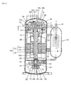
- FIG. 2 is a longitudinal cross-sectional view of the hermetic compressor and an oil collecting apparatus shown in FIG. 1 ;
- FIG. 3 is a view taken along the line I - I of FIG. 2 ;
- FIG. 4 is a disassembled view of an oil supply device shown in FIG. 2 ;
- FIG. 5 is a view taken along the line II - II of FIG. 2 ;
- FIG. 6 is a view of an upper surface of a pump cover shown in FIG. 2 ;
- FIG. 7 is a cross-sectional view of compression chambers of a hermetic compressor in accordance with the invention.
- FIG. 8 is a longitudinal cross-sectional view of a hermetic compressor and an oil collecting apparatus in accordance with the invention.
- FIG. 9 is a schematic view of a refrigeration cycle
- FIG. 10 illustrates a pipe connected state with the inside of a compressor shown in FIG. 9 ;
- FIG. 11 illustrates a pipe connected state with the inside of a compressor in a refrigerating cycle.
- An oil collecting apparatus that separates oil from compressed fluid and collects the separated oil into an inner space of the compressor has recently been developed. Recently, as variable compression capacity has become desirable and the size of refrigeration loads during a compression operation has increased, refrigeration cycles having a plurality of compressors are being used so that cooling performance may be adjusted and compression capacity may be varied by operating all or some of the plurality of compressors.
- Appropriately distributing separated and collected oil to each compressor to compensate for a difference in oil levels among the plurality of compressors caused by a difference in an amount of oil discharged between operating and non-operating compressors and between operating compressors is required.
- a distribution approach in which an outlet of an oil collecting apparatus provided with each compressor is connected to a common suction line, which is in turn connected to a suction pipe of each compressor may be considered. This collects all the oil/refrigerant in a central area. However, the oil is at a relatively high temperature compared to the refrigerant, which increases a specific volume of the refrigerant, resulting in a degradation of compression efficiency.
- the hermetic compressor 100 shown in FIGs. 1-3 is included in a refrigeration cycle together with a condenser 20, an expansion device 30, and an evaporator 40.
- a suction pipe 113 coupled to a casing 110 may be connected to the evaporator 40, and a discharge pipe 114 may be connected to the condenser 20.
- the hermetic compressor 100 may also include a driving device 120, a compressing device 130, an oil separator 50 installed between a discharge side of the hermetic compressor 100 and an inlet side of the condenser 20, for separating oil mixed with a refrigerant discharged via the discharge pipe 114, and an oil collecting pipe 180 that supplies oil separated in the oil separator 50 to the compressing device 130.
- the casing 110 may form a hermetic inner space.
- the suction pipe 113 introduces a low pressure gaseous refrigerant, that has passed through the evaporator 40, into the compressor 100, and the discharge pipe 114 receives a compressed high pressure gaseous refrigerant for discharge from the compressor 100.
- the inner space of the casing 110 may be provided with a main frame 111 supporting one end of the driving device 120 and the compressing device 130 driven by the driving device 120 to compress a refrigerant, and a sub frame 112 supporting another end of the driving device 120.
- An oil supply hole 115 through which oil is injected into the inner space of the casing 110 may be formed at a lower portion of the casing 110.
- the oil supply hole 115 may be used as an oil equalizing hole for communicating with the plurality of compressors so as to equalize an oil level of each compressor.
- the driving device 120 may include a driving motor 121 installed in the inner space of the casing 110 for generating a driving force, and a rotational shaft 123 coupled to the driving motor 121.
- the driving motor 121 may include a stator 121a fixed to an inner circumferential surface of the casing 110, and a rotor 121b rotatably disposed inside the stator 121a.
- the rotational shaft 123 may be coupled to the center of the rotor 122b, and may be supported by the main and sub frames 111 and 112 so as to transfer a rotational force of the rotor 121b to the compressing device 130.
- An oil passage 123a may penetrate through the rotational shaft 123 in the longitudinal shaft direction so as to allow oil supplied to the compressing device 130 to flow up therethrough.
- the compressing device 130 may include a fixed scroll 131 and a orbiting scroll 132 that both operate in cooperation with the rotational shaft 123.
- the fixed scroll 131 may be coupled to the main frame 111, and may include an outlet 131c through which a compressed refrigerant is discharged, and a check valve 134 that blocks a backflow of gas discharged via the outlet 131c.
- the orbiting scroll 132 may be supported by the main frame 111, engaged with the fixed scroll 131, and may orbit in cooperation with the rotational shaft 123.
- An Oldham ring 133 that provides for the orbiting motion of the orbiting scroll 132 may be disposed between the orbiting scroll 132 and the main frame 111.
- the fixed scroll 131 and the orbiting scroll 132 may include a fixed wrap 131a and an orbiting wrap 132a, respectively, which are radially formed and engaged with each other to consecutively form a pair of compression chambers P.
- the compression chambers P may be formed by the fixed wrap 131a of the fixed scroll 131 and the orbiting wrap 132a of the orbiting scroll 132, which orbits with respect to the fixed scroll 131.
- Internal volumes of the pair of compression chambers P may be varied by the rotation of the orbiting scroll 132, so as to compress a refrigerant held therein.
- the compression chambers P may move toward the central portion of the fixed scroll 131 in cooperation with the rotation of the orbiting scroll 132.
- a compressed refrigerant may be discharged via the outlet 131c of the fixed scroll 131.
- the suction pipe 113 may be directly connected to an inlet 131b of the fixed scroll 131, and the outlet 131c of the fixed scroll 131 may communicate with the inner space of the casing 110. Accordingly, refrigerant contained within the inner space of the casing 110 may have substantially the same pressure as a discharge pressure, as in a 'high pressure type hermetic compressor'.
- a suction side of the compressing device 130 may communicate with the inner space of the casing 110 and the discharge pipe 114 may be directly connected to the discharge side of the compressing device 130, as in a low pressure type hermetic compressor'.
- FIG. 2 A high pressure type hermetic compressor is shown in FIG. 2 , merely for ease of discussion. However, the principles set forth herein may also be applicable to the low pressure type hermetic compressor.
- the oil separator 50 is a device that separates oil from refrigerant that has been discharged from the casing 110.
- the oil separator 50 may be connected to the discharge pipe 114 of the compressor 100.
- An oil-separated refrigerant may be supplied to the condenser 20 via an exhaust pipe 55, and the separated oil flows toward the compressing device 130 via the oil collecting pipe 180.
- the oil separator 50 may be cylindrically formed with a hermetic inner space, and may be disposed in parallel at one side of the casing 110.
- the oil separator 50 may be connected to the oil collecting pipe 180 and supported at the casing 110 or by a separate supporting member 52, such as a clamp.
- a method using a mesh screen installed in the inner space of the oil separator 50 may be used to allow separation between refrigerant and oil, or a method in which the discharge pipe 114 may be off-set with respect to an axial center of the oil separator 50 so as to generate a cyclonic flow and cause relatively heavy oil to be separated from the refrigerant.
- Other methods may also be appropriate.
- a first end of the oil collecting pipe 180 may be coupled to the lower portion of the oil separator 50 in which the separated oil is stored, and a second end may be coupled to the compressing device 130, so as to allow the separated oil to be supplied to the compression chambers P of the compressing device 130.
- the oil collecting pipe 180 may also include a decompressing device 181 such as, for example, a capillary tube. Accordingly, oil or refrigerant from the compression chambers P may be prevented from flowing back into the inner space of the oil separator 50.
- the oil collecting pipe 180 may penetrate through the fixed scroll 131 so as to provide for communication between the compression chambers P and the outlet of the oil separator 50.
- the compression chambers P are formed as a pair (i.e., P1 and P2) at positions symmetrical to each other with respect to the center of the fixed scroll 131. Internal pressures of the pair of compression chambers P1 and P2 are substantially the same.
- the oil collecting pipe 180 may communicate simultaneously with the pair of compression chambers P1 and P2.
- the compression chambers P move toward the central portion of the fixed scroll 131 in cooperation with the orbiting motion of the orbiting scroll 132, thus to compress a refrigerant held therein.
- the internal pressures of the pair of compression chambers P may be equalized by making the compression chambers P1 and P2 move the same distance in cooperation with the orbiting motion of the orbiting scroll 132.
- the oil collecting pipe 180 communicates with the pair of compression chambers P1 and P3 at the beginning of the compression operation. That is, the oil collecting pipe 180 may be configured such that oil is supplied to the compression chambers P1 and P2 just after the compression chambers P1 and P2 are created by the fixed wrap 131a and the orbiting wrap 132a. Accordingly, oil may be smoothly and consistently supplied to the compression chambers P1 and P2 in a relatively low pressure state. Also, since at this point in operation the volumes of the compression chambers P1 and P2 have been established, a problem of an increase in a specific volume of refrigerant due to oil mixed therein can be prevented.
- an end of the oil collecting pipe 180 may be respectively connected to the pair of compression chambers P1 and P2, and oil may simultaneously be supplied into each of the compression chambers P1 and P2 via the oil collecting pipe 180.
- the oil collecting pipe 180 may diverge at a certain point to reach each of the compression chambers P1 and P2.
- a pair of oil supply channels 180a and 180b may be formed in the fixed scroll 131 to provide for communication between the compression chambers P1 and P2 and the oil collecting pipe 180.
- the pair of oil supply channels 180a and 180b may have the same length.
- This may lie at the center of a circular trace along which a certain point of the orbiting wrap 132 moves in cooperation with the orbiting motion of the orbiting scroll 132, as shown in FIG. 3 . Accordingly, as the orbiting scroll 132 orbits, oil supplied through the ends of the oil supply channels 180a and 180b, or the end of the oil collecting pipe 180, may be alternately supplied to the pair of compression chambers P1 and P2.
- a hermetic compressor 100 in accordance with this embodiment may also include an oil supply device 140 that supplies oil stored in the casing 110 to the compressing device 130 and the driving device 120, as shown in FIGs. 4-6 .
- the oil supply device 140 may include an oil pump 150 coupled to the rotational shaft 123, including a capacity variable portion 150a to perform a pumping operation, a pump housing 141 installed inside the casing 110 to accommodate the oil pump 150, and a pump cover 142 coupled to the pump housing 141 to supply oil to the oil pump 150.
- the pump housing 141 may include a pump accommodating portion 141b that receives the oil pump 150, and a pin receiving portion 141a having a pin 123b, extending from the rotational shaft 123, inserted therethrough.
- the pump housing 141 may be coupled to a lower portion of the sub frame 112, or integrally may be formed with the sub frame 112.
- the oil pump 150 may be configured as a volumetric pump such as, for example, a trochoid gear pump, which pumps oil with varying capacity, or other pump type as appropriate.
- the oil pump 150 includes an inner gear 151 rotatably accommodated in the pump accommodating portion 141b and coupled to the rotational shaft 123 to eccentrically rotate, and an outer gear 152 rotatably disposed at the pump accommodating portion 141b so as to form the capacity variable portion 150a through engagement with the inner gear 151.
- the oil pump 150 may be operated by the rotational shaft 123 to pump oil contained in the inner space of the casing 110 or oil separated from refrigerant that has been discharged out of the compressing device 130.
- the pumped oil flows upwardly along the oil passage 123a, so as to lubricate the compressing device 130 and simultaneously cool the driving motor 121.
- the pump cover 142 may include an oil suction hole 142b through which oil may be drawn up from the bottom of the casing 110.
- the oil suction hole 142b may be formed in a shaft direction so as to communicate with an oil suction pipe 148 through which oil contained in the casing 110 is drawn up.
- an inlet of the oil suction pipe 148 may be formed long enough to be submerged the oil contained in the casing 110.
- the pump cover 142 may also include a communicating groove 153 formed in a central portion of an upper surface of the pump cover 142 such that the oil passage 123a of the rotational shaft 123 may extend therethrough.
- a suction guide groove 155 may be formed around one side of the communicating groove 153 so as to communicate with the oil suction hole 142b.
- a discharge guide groove 156 may be formed at a position spaced apart from the suction guide groove 155 in a circumferential direction to discharge oil pumped by the oil pump 150.
- the suction and discharge guide grooves 155 and 156 may have an arcuate shape, or other shape as appropriate.
- a discharge slot 157 may be formed at an inner wall of the discharge guide groove 156, in communication with the communicating groove 153.
- the capacity variable portion 150a may be configured by a suction capacity part V1 and a discharge capacity part V2.
- a capacity of the suction capacity part V1 may be gradually increased from a start point to an end point in the circumferential direction of the suction guide groove 155, along a rotating direction of the inner gear 151, and the discharge capacity part V2 may be connected to the suction capacity part V1, and its capacity may be decreased from a start point of the discharge guide groove 156 to an end point thereof, along the rotating direction of the inner gear 151.
- the inner gear 151 of the oil pump 150 is coupled to the rotational shaft 123, causing the inner gear 151 to eccentrically rotate, and accordingly the suction capacity part V1 and the discharge capacity part V2 are formed between the inner gear 151 and the outer gear 152.
- the suction capacity part V1 is in communication with the oil suction hole 142b.
- the oil contained in the bottom of the casing 110 is introduced in the suction guide groove 155 via the oil suction pipe 148 and the oil suction hole 142b. Accordingly, the oil introduced into the suction guide groove 155 flows from the suction capacity part V1 to the discharge capacity part V2.
- the oil in the discharge capacity part V2 is then introduced into the discharge guide groove 156, and then into the communicating groove 153 via the discharge slot 157 formed at the inner circumferential wall surface of the discharge guide groove 156.
- the oil is then drawn from the communicating groove 153 into the oil passage 123a of the rotational shaft 123.
- the oil drawn into the oil passage 123a is pushed up through the oil passage 123a by a centrifugal force of the rotational shaft 123. During this process, part of the oil is supplied to each bearing surface, and the remainder of the oil is scattered at the upper end of the oil passage 123a, where it is introduced in the compressing device 130. These steps may be repeatedly performed.
- oil is introduced during a compression process which is performed after a refrigerant is drawn into a compressing device of the hermetic compressor, which may prevent loss of compression efficiency due to an increase in a specific volume of a refrigerant with oil supplied to a suction side of the hermetic compressor.
- a method of collecting oil that has been separated in an oil separator and supplying it to compression chambers, other than supplying such oil to a suction side of a hermetic compressor, may also be applied.
- the oil separated in the oil separator is directly introduced into the compression chambers of the compressing device via the oil collecting pipe.
- a simple configuration may be implemented compared to the above method, whereby reliability may be enhanced and fabricating cost may be reduced.
- the oil separated in the oil separator is directly introduced into the compression chambers of the compressing device via the oil collecting pipe, lubrication of compressing device and reliability of cooling operation may be improved, resulting in improved compressor performance.
- FIG. 7 is a cross-sectional view of compression chambers of a hermetic compressor in accordance with another embodiment as broadly described herein.
- the embodiment of the hermetic compressor 200 shown in FIG. 7 may have a similar configuration to the hermetic compressor 100 shown in FIGs. 1-6 . However, the structure of the compression chambers P and the structure of an oil collecting pipe 280 that supplies oil to the compression chambers P is different.
- the compression chambers P may be formed as a pair P1 and P2, at positions symmetrical to each other with respect to the center of a fixed scroll 231, and the compression chambers P1 and P2 may have different internal pressures.
- This type of hermetic compressor may be referred to as an 'asymmetrical hermetic compressor' in contrast with the aforesaid 'symmetrical hermetic compressor'.
- a refrigerant may start to be compressed at a position close to a suction portion 231 b of a compression space formed by a fixed wrap 231a of the fixed scroll 231, which is advantageous in enhancing compression performance.
- an end of the oil collecting pipe 280 may be formed at a position which alternately communicates with the pair of compression chambers P1 and P2.
- the end of the oil collecting pipe 280 may be disposed at the center of a circular trace along which a certain point of an orbiting wrap 232a moves in cooperation with the orbiting motion of an orbiting scroll 232.
- FIG. 8 Another embodiment of a hermetic compressor as broadly described herein will be discussed in more detail with reference to FIG. 8 .
- FIG. 8 is a longitudinal cross-sectional view of a hermetic compressor and an oil collecting apparatus in accordance with another embodiment as broadly described herein.
- the hermetic compressor 300 shown in FIG. 8 may include an oil separator 250 installed within a casing 310 of the hermetic compressor 300.
- Refrigerant compressed in the compressing device 130 may be discharged into the casing 310. While the refrigerant circulates inside the casing 310, oil may be partially separated from the refrigerant and flow down to a lower portion of the casing 310. The remaining non-separated oil and the compressed refrigerant may be introduced into the oil separator 250 via an inlet 252 of the oil separator 250.
- oil separated in the oil separator 250 may be collected at the bottom of a case 251 of the oil separator 250, and then supplied to the compression chambers P via an oil collecting pipe 380 that extends between the lower portion of the case 251 and the compression chambers P.
- FIG. 9 is a schematic view of a refrigeration cycle and FIG. 10 illustrates a pipe connected state with the inside of one of the compressors shown in FIG. 9 .
- a refrigeration cycle 10 may include a condenser 20 that condenses a refrigerant therein into a liquid refrigerant at intermediate temperature and high pressure, an expansion device 30 that decompresses the refrigerant discharged from the condenser 20 to a liquid refrigerant at low temperature and low pressure, and an evaporator 40 that evaporates the refrigerant discharged from the expansion device 30 as a gaseous refrigerant at high temperature and low pressure using heat adsorbed from the exterior.
- the refrigeration cycle 10 may include a plurality of compressors 100a, 100b and 100c for compressing the refrigerant discharged from the evaporator 40 into a gaseous refrigerant at high temperature and high pressure.
- the plurality of compressors 100a, 100b and 100c may each include oil separators 50a, 50b and 50c, respectively, for separating oil from a refrigerant discharged therefrom.
- the oil separators 50a, 50b and 50c may be respectively connected to refrigerant pipes 55a, 55b and 55c through which the refrigerant is discharged, and may also be respectively connected to oil converging pipes 101a, 101b and 101c through which separated oil is collected.
- the refrigerant pipes 55a, 55b and 55c may be connected to the condenser 20, and the oil converging pipes 101a, 101b and 101c may converge into one to be connected to the connection pipe 109.
- the connection pipe 109 may then connected to oil supply pipes 103a, 103b and 103c through which oil collected via the oil converging pipes 101a, 101b and 101c is supplied into each of the compressors 100a, 100b and 100c.
- the oil supply pipes 103a, 103b and 103c may be provided with control valves 105a, 105b and 105c, respectively, for controlling oil supply based on an operation state of the compressors 100a, 100b and 100c respectively connected thereto.
- the control valves 105a, 105b and 105c may be configured as a valve such as, for example, a solenoid, which may control oil introduction into non-operating compressors and prevent oil discharge therefrom. Other types of valves may also be appropriate.
- the plurality of compressors 100a, 100b and 100c are all operated. Oil discharged from each of the compressors 100a, 100b and 100c flows sequentially via the oil converging pipes 101a, 101b and 101c, the connection pipe 109 and the oil supply pipes 103a, 103b and 103c, and is supplied back into each of the compressors 100a, 100b and 100c.
- the control valves 105a, 105b and 105c disposed at the oil supply pipes 103a, 103b and 103c are all open at this point.
- An amount of oil supplied to each of the compressors 100a, 100b and 100c is supplied in proportion to their rotation velocities. Hence, more oil is supplied to a compressor in which a large amount of refrigerant is drawn, which facilitates an appropriate oil distribution among the compressors.
- decompressing units 107a, 107b and 107c may be provided respectively at the oil converging pipes 101a, 101b and 101c so as to lower pressure and prevent the backflow of oil discharged from the oil separators 50a, 50b and 50c.
- the oil supply pipes 103a, 103b and 103c may communicate with the compression chambers P formed within the plurality of compressors 100a, 100b and 100c.
- the compressor 100a may include a compressor casing 110, a driving motor 121, a compressing device 130, an oil separator 50a disposed at a pipe connecting a discharge side of the compressor 100a to an inlet of the condenser 20 for separating oil from refrigerant discharged via the discharge pipe 114, and an oil converging pipe 101a, a connection pipe 109 and an oil supply pipe 103a all for supplying oil separated in the oil separator 50a to the compressing device 130.
- the oil separator 50a is a device that separates oil from a refrigerant discharged out of the casing 110.
- the oil separator 50a is connected to the discharge pipe 114 of the compressor 100a.
- the oil-separated refrigerant is supplied into the condenser 20 via the refrigerant pipe 55a, and the separated oil is supplied into the compression chambers P of the compressing device 130 sequentially via the oil converging pipe 101a, the connection pipe 109 and the oil supply pipe 103a.
- One end of the oil converging pipe 101a is connected to the lower portion of the oil separator 50a in which the separated oil is stored, and another end is converged with the oil converging pipes 101b and 101c for collecting the separated oil from the other compressors 100b and 100c.
- connection pipe 109 One end of the connection pipe 109 is connected to the oil converging pipes 101a, 101b, 101c, and the other end of the connection pipe 109 is connected to the oil supply pipe 103a connected to each of the compression chambers P.
- the control valve 105a is disposed at the oil supply pipe 103a so as to control whether flows of oil through oil supply pipe 103a.
- the control valve 105a is open upon the operation of the compressor 100a, while being closed upon the non-operation thereof.
- the decompressing unit 107a such as, for example, a capillary tube may be provided at the oil converging pipe 101a. Accordingly, refrigerant discharged out of the oil separator 50a may be prevented from flowing backward.
- the compression chambers P may be implemented in various structures as described above, and the oil supply pipe 103a may simultaneously communicate with the pair of compression chambers P.
- oil separated in each of the oil separators provided at a plurality of compressors is collected into oil converging pipes and then directly supplied to each compressor.
- more oil may be supplied into a compressor with a larger refrigerant flow, so as to improve reliability among the plurality of compressors.
- oil may be directly supplied to the compression chambers of each compressor via oil supply pipes so as to supply oil to suction lines of a plurality of compressors, thereby preventing degradation of compression performance.
- FIG. 11 illustrates a pipe connected state with the inside of one compressor in a refrigerating cycle in accordance with another embodiment as broadly described herein.
- a compressor 400a may include an oil separator 450a installed within the casing 110 of the compressor 400a.
- this embodiment has substantially the same or similar configuration to the embodiment described above, excluding that oil separators 250a, 250b and 250c are installed within a plurality of compressors 400a, 400b and 400c, respectively.
- a refrigerant compressed in the compressing device 130 is discharged into the casing 110 so as to circulate inside the casing 110.
- part of the oil is separated from the refrigerant and flows down to a lower portion of the casing 110.
- the remaining non-separated oil and the compressed refrigerant are introduced into the oil separator 450a via an inlet 452 of the oil separator 450a located within the casing 110.
- oil separated in the oil separator 450a is collected in the bottom of the case 451 of the oil separator 450a.
- the lower portion of the case 451 is connected to the oil converging pipe 401a for collecting oil, and the oil converging pipe 401a is connected to oil supply pipes 403a, 403b and 403c via the connection pipe 409. Accordingly, such collected oil in the lower portion of the case 451 flows via the oil converging pipe 401a and is supplied to the compression chambers P through the oil supply pipes 403a, 403b and 403c via the connection pipe 409.
- a hermetic compressor is provided that is capable of improving a performance of a compressor as well as minimizing an increase in a fabricating cost due to a simple configuration of an oil collecting apparatus.
- a refrigeration cycle having the hermetic compressor in plurality which employs an oil distributing method among the plurality of compressors, capable of minimizing an increase in a fabricating cost and preventing a degradation of compression efficiency of the compressors.
- a hermetic compressor as embodied and broadly described herein may include a casing having a hermetic inner space and having suction pipe and discharge pipe connected thereto; a driving motor installed within the inner space of the casing and configured to generate a driving force; a compressing unit installed within the inner space of the casing and operated by the driving motor to form compression chambers for compressing a refrigerant; an oil separator configured to separate oil from a refrigerant discharged from the compressing unit; and an oil collecting pipe through which the oil separator is communicated with the compression chambers such that oil separated in the oil separator is supplied into the compression chambers.
- the compression chambers may be formed by a fixed wrap of a fixed scroll fixed to the inner space of the casing and an orbiting wrap of an orbiting scroll which orbits with respect to the fixed scroll in cooperation with the driving motor, and the oil collecting pipe penetrates through the fixed scroll to be communicated with the compression chambers.
- the oil collecting pipe may be communicated with the compression chambers at the beginning of the compression of a refrigerant.
- the hermetic compressor may also include a decompressing unit disposed at the oil collecting pipe on a path through which oil flows from an outlet of the oil separator into the compression chambers.
- the compression chambers in which oil is supplied may be formed as a pair at symmetrical positions to each other with respect to the center of the fixed scroll, and have the same internal pressure, each compression chamber being simultaneously communicated with the oil collecting pipe.
- the pair of compression chambers may be communicated with the oil collecting pipe via a pair of oil supply channels formed at the fixed scroll.
- the lengths of the oil supply channels for connecting the oil collecting pipe to each compression chamber may be the same.
- An end of each oil supply channel communicated with the compression chambers may be located at the center of a circular trace along which a certain point of the end of the orbiting wrap moves in cooperation with the orbiting motion of the orbiting scroll.
- the compression chambers in which oil is supplied may be formed as a pair to be symmetrical to each other with respect to the center of the fixed scroll, and each compression chamber is configured to have a different internal pressure, each compression chamber being alternately communicated with the oil collecting pipe.
- each oil supply channel communicated with the compression chambers may be located at the center of a circular trace along which a certain point of the end of the orbiting wrap moves in cooperation with the orbiting motion of the orbiting scroll.
- a refrigeration cycle as embodied and broadly described herein may include a plurality of hermetic compressors; a plurality of oil separators configured to separate oil from a refrigerant discharged from the plurality of compressors; oil converging pipes configured to collect oil separated by the plurality of oil separators into one portion; oil supply pipes configured to supply oil collected via the oil converging pipes into each compressor; and control valves disposed at the oil supply pipes, respectively, to control whether to supply oil.
- Each of the plurality of compressors may include a casing having a hermetic inner space and having suction pipe and discharge pipe connected thereto, a driving motor installed within the inner space of the casing and configured to generate a driving force, and a compressing unit installed within the inner space of the casing and operated by the driving motor to form compression chambers for compressing a refrigerant, wherein the oil supply pipes are communicated with the compression chambers.
- the control valves may control such that an oil introduction into the compression chambers of a non-operating compressor and an oil discharge therefrom are prevented.
- a decompressing unit may be provided at each oil converging pipe.
- any reference in this specification to "one embodiment,” “an embodiment,” “example embodiment,” “certain embodiment,” “alternative embodiment,” etc. means that a particular feature, structure, or characteristic described in connection with the embodiment is included in at least one embodiment as broadly described herein.
- the appearances of such phrases in various places in the specification are not necessarily all referring to the same embodiment.
Landscapes
- Engineering & Computer Science (AREA)
- Mechanical Engineering (AREA)
- General Engineering & Computer Science (AREA)
- Physics & Mathematics (AREA)
- Thermal Sciences (AREA)
- Chemical & Material Sciences (AREA)
- Analytical Chemistry (AREA)
- Power Engineering (AREA)
- Applications Or Details Of Rotary Compressors (AREA)
- Rotary Pumps (AREA)
- Compressor (AREA)
Claims (5)
- Compresseur, comprenant :un carter (110) qui définit un espace intérieur hermétique ;un tuyau d'aspiration (113) et un tuyau d'évacuation (114) qui sont chacun couplés au carter (110) ;un moteur d'entraînement (121) fourni dans l'espace intérieur ;un dispositif de compression (130) fourni dans l'espace intérieur, dans lequel le dispositif de compression (130) reçoit une force d'entraînement du moteur d'entraînement (121) et fonctionne pour former des chambres de compression (P1, P2) qui compressent un réfrigérant en réponse à celle-ci ;un séparateur d'huile (50) qui sépare l'huile du réfrigérant évacué du dispositif de compression (130) ; etun conduit de collecte d'huile (180) qui s'étend entre le séparateur d'huile (50) et le dispositif de compression (130), dans lequel le conduit de collecte d'huile (180) reçoit de l'huile du séparateur d'huile (50) et dirige l'huile reçue vers les chambres de compression (P1, P2) formées dans le dispositif de compression (130),dans lequel le dispositif de compression (130) comprend une spirale fixe (131) et une spirale orbitale (132) qui sont chacune fournies dans l'espace intérieur, dans lequel un enroulement fixe (131a) de la spirale fixe (131) et un enroulement orbital (132a) de la spirale orbitale (132) coopèrent afin de former les chambres de compression pendant que la spirale orbitale tourne en orbite autour de la spirale fixe en réponse à la force d'entraînement générée par le moteur d'entraînement (121),caractérisé en ce que le conduit de collecte d'huile (180) pénètre à travers la spirale fixe (131) afin de communiquer avec les chambres de compression (P1, P2), etdans lequel le conduit de collecte d'huile (180) est configuré de sorte que de l'huile est fournie aux chambres de compression (P) juste après la création des chambres de compression (P1, P2) dans le dispositif de compression (130).
- Compresseur selon la revendication 1, comprenant en outre un dispositif de décompression (181) pourvu du conduit de collecte d'huile (180), dans lequel le dispositif de décompression (181) est fourni à une portion du conduit de collecte d'huile (180) entre une sortie du séparateur d'huile (50) et une entrée dans les chambres de compression (P1, P2).
- Compresseur selon la revendication 1, dans lequel le conduit de collecte d'huile (180) comprend une paire de canaux d'alimentation d'huile (180a, 180b) qui pénètrent chacun dans la spirale fixe (131) afin de fournir simultanément de l'huile aux chambres de compression (P1, P2).
- Compresseur selon la revendication 3, dans lequel les chambres de compression (P1, P2) comprennent une paire de chambres de compression qui sont formées à des positions symétriques par rapport à un centre de la spirale fixe (131), dans lequel une pression interne de la paire de chambres de compression est sensiblement identique, et dans lequel la paire de canaux d'alimentation d'huile (180a, 180b) s'étendent respectivement jusqu'à la paire de chambres de compression afin de fournir simultanément de l'huile à celles-ci.
- Compresseur selon la revendication 1, dans lequel les chambres de compression (P1, P2) comprennent une paire de chambres de compression qui sont formées à des positions symétriques par rapport à un centre de la spirale fixe (131), dans lequel une pression interne d'une première de la paire de chambres de compression est différente de celle d'une deuxième de la paire de chambres de compression, et dans lequel une extrémité du conduit de collecte d'huile (180) communique alternativement avec la paire de chambres de compression afin de fournir alternativement de l'huile à celles-ci.
Applications Claiming Priority (2)
| Application Number | Priority Date | Filing Date | Title |
|---|---|---|---|
| KR20080106129A KR101480467B1 (ko) | 2008-10-28 | 2008-10-28 | 밀폐형 압축기 |
| KR1020080106128A KR101545580B1 (ko) | 2008-10-28 | 2008-10-28 | 냉동 사이클 |
Publications (3)
| Publication Number | Publication Date |
|---|---|
| EP2182307A2 EP2182307A2 (fr) | 2010-05-05 |
| EP2182307A3 EP2182307A3 (fr) | 2010-06-09 |
| EP2182307B1 true EP2182307B1 (fr) | 2012-09-12 |
Family
ID=41614976
Family Applications (1)
| Application Number | Title | Priority Date | Filing Date |
|---|---|---|---|
| EP09174122A Not-in-force EP2182307B1 (fr) | 2008-10-28 | 2009-10-27 | Compresseur hermétique |
Country Status (3)
| Country | Link |
|---|---|
| US (1) | US8037712B2 (fr) |
| EP (1) | EP2182307B1 (fr) |
| CN (1) | CN101725528A (fr) |
Families Citing this family (11)
| Publication number | Priority date | Publication date | Assignee | Title |
|---|---|---|---|---|
| TR201905507T4 (tr) * | 2010-10-13 | 2019-05-21 | Toshiba Carrier Corp | Hermetik olarak kapatılmış döner kompresör ve soğutma döngüsü cihazı. |
| JP5255157B2 (ja) * | 2011-03-18 | 2013-08-07 | パナソニック株式会社 | 圧縮機 |
| US9284955B2 (en) | 2011-03-18 | 2016-03-15 | Panasonic Intellectual Property Management Co., Ltd. | Compressor |
| CN103534487B (zh) * | 2011-05-16 | 2016-08-17 | 松下电器产业株式会社 | 压缩机 |
| JP5360258B2 (ja) * | 2012-04-04 | 2013-12-04 | パナソニック株式会社 | 圧縮機 |
| US10047987B2 (en) | 2013-02-05 | 2018-08-14 | Emerson Climate Technologies, Inc. | Compressor cooling system |
| JPWO2015140880A1 (ja) * | 2014-03-17 | 2017-04-06 | 三菱電機株式会社 | 圧縮機及び冷凍サイクル装置 |
| JP2018100641A (ja) * | 2016-12-21 | 2018-06-28 | 三菱重工サーマルシステムズ株式会社 | 圧縮機ユニット及びこれを備えた室外機 |
| CN109185104B (zh) * | 2018-09-19 | 2024-06-21 | 珠海凌达压缩机有限公司 | 压缩机 |
| DE102021101627B4 (de) | 2021-01-26 | 2023-05-04 | Sanden International (Europe) GmbH | Spiralverdichter mit direkter Ölrückführung von einem Ölabscheider in einen Kompressionsabschnitt |
| KR20230083389A (ko) * | 2021-12-02 | 2023-06-12 | 엘지전자 주식회사 | 스크롤 압축기 |
Family Cites Families (15)
| Publication number | Priority date | Publication date | Assignee | Title |
|---|---|---|---|---|
| US4180986A (en) * | 1978-04-25 | 1980-01-01 | Dunham-Bush, Inc. | Refrigeration system on/off cycle |
| JPS55107093A (en) | 1979-02-13 | 1980-08-16 | Hitachi Ltd | Enclosed type scroll compressor |
| US4335582A (en) * | 1981-02-20 | 1982-06-22 | Dunham-Bush, Inc. | Unloading control system for helical screw compressor refrigeration system |
| JPH0617676B2 (ja) * | 1985-02-15 | 1994-03-09 | 株式会社日立製作所 | ヘリウム用スクロ−ル圧縮機 |
| US4829786A (en) | 1988-08-15 | 1989-05-16 | American Standard Inc. | Flooded evaporator with enhanced oil return means |
| JPH02287067A (ja) | 1989-04-27 | 1990-11-27 | Daikin Ind Ltd | 並列運転される複数圧縮機用油分離器 |
| JP2538078B2 (ja) | 1989-11-02 | 1996-09-25 | 松下電器産業株式会社 | スクロ―ル圧縮機 |
| JPH07146018A (ja) | 1993-11-22 | 1995-06-06 | Hitachi Ltd | マルチタイプスクリュウ冷凍機 |
| ES2211908T3 (es) * | 1994-06-29 | 2004-07-16 | Daikin Industries, Ltd. | Refrigerador. |
| US6017205A (en) * | 1996-08-02 | 2000-01-25 | Copeland Corporation | Scroll compressor |
| JPH11303776A (ja) | 1998-04-21 | 1999-11-02 | Hitachi Ltd | スクロール圧縮機およびそれを用いた冷凍サイクル |
| US6125642A (en) | 1999-07-13 | 2000-10-03 | Sporlan Valve Company | Oil level control system |
| US20070214827A1 (en) | 2006-03-20 | 2007-09-20 | Chadalavada Venkatasubramaniam | Oil-free refrigerant circulation technology for air-conditioning and refrigeration system |
| KR20070106875A (ko) | 2006-05-01 | 2007-11-06 | 삼성전자주식회사 | 내부진입형 배출관을 갖춘 밀폐용기 및 이를 이용한오일분리기, 기액분리기, 공조장치 |
| KR100878819B1 (ko) | 2007-03-02 | 2009-01-14 | 엘지전자 주식회사 | 공기조화기 및 그 제어방법 |
-
2009
- 2009-10-15 US US12/579,629 patent/US8037712B2/en not_active Expired - Fee Related
- 2009-10-27 EP EP09174122A patent/EP2182307B1/fr not_active Not-in-force
- 2009-10-28 CN CN200910208117A patent/CN101725528A/zh active Pending
Also Published As
| Publication number | Publication date |
|---|---|
| CN101725528A (zh) | 2010-06-09 |
| EP2182307A2 (fr) | 2010-05-05 |
| US8037712B2 (en) | 2011-10-18 |
| EP2182307A3 (fr) | 2010-06-09 |
| US20100101270A1 (en) | 2010-04-29 |
Similar Documents
| Publication | Publication Date | Title |
|---|---|---|
| EP2182307B1 (fr) | Compresseur hermétique | |
| US7473083B2 (en) | Oil separating device for compressor | |
| US8992191B2 (en) | Scroll compressor with differential pressure hole | |
| EP2020578B1 (fr) | Compresseur hermétique et dispositif de cycle de réfrigération en disposant | |
| EP2115302B1 (fr) | Compresseur et dispositif de blocage d'huile pour celui-ci | |
| US11248608B2 (en) | Compressor having centrifugation and differential pressure structure for oil supplying | |
| EP2187059B1 (fr) | Compresseur hermétique et dispositif de cycle de réfrigération en disposant | |
| EP2243958A2 (fr) | Compresseur et appareil de réfrigération en disposant | |
| CN110118180B (zh) | 涡旋压缩机 | |
| EP2187060B1 (fr) | Compresseur hermétique et dispositif de cycle de réfrigération en disposant | |
| EP2020577B1 (fr) | Compresseur | |
| KR101964962B1 (ko) | 냉매 역류 방지 구조가 구비된 압축기 | |
| KR20090013041A (ko) | 밀폐형 압축기 및 이를 적용한 냉동사이클 장치 | |
| KR101480467B1 (ko) | 밀폐형 압축기 | |
| KR101275185B1 (ko) | 압축기 | |
| US20230175510A1 (en) | Scroll compressor | |
| JP2008008263A (ja) | 電動圧縮機 | |
| KR20200109621A (ko) | 스크롤 압축기 | |
| KR101545580B1 (ko) | 냉동 사이클 | |
| KR101474462B1 (ko) | 밀폐형 압축기 | |
| KR101474461B1 (ko) | 밀폐형 압축기 | |
| KR20020061798A (ko) | 냉동사이클용 회전압축기 |
Legal Events
| Date | Code | Title | Description |
|---|---|---|---|
| PUAI | Public reference made under article 153(3) epc to a published international application that has entered the european phase |
Free format text: ORIGINAL CODE: 0009012 |
|
| 17P | Request for examination filed |
Effective date: 20091124 |
|
| AK | Designated contracting states |
Kind code of ref document: A2 Designated state(s): AT BE BG CH CY CZ DE DK EE ES FI FR GB GR HR HU IE IS IT LI LT LU LV MC MK MT NL NO PL PT RO SE SI SK SM TR |
|
| AX | Request for extension of the european patent |
Extension state: AL BA RS |
|
| PUAL | Search report despatched |
Free format text: ORIGINAL CODE: 0009013 |
|
| AK | Designated contracting states |
Kind code of ref document: A3 Designated state(s): AT BE BG CH CY CZ DE DK EE ES FI FR GB GR HR HU IE IS IT LI LT LU LV MC MK MT NL NO PL PT RO SE SI SK SM TR |
|
| AX | Request for extension of the european patent |
Extension state: AL BA RS |
|
| 17Q | First examination report despatched |
Effective date: 20110207 |
|
| REG | Reference to a national code |
Ref country code: DE Ref legal event code: R079 Ref document number: 602009009664 Country of ref document: DE Free format text: PREVIOUS MAIN CLASS: F25B0031000000 Ipc: F25B0001040000 |
|
| GRAP | Despatch of communication of intention to grant a patent |
Free format text: ORIGINAL CODE: EPIDOSNIGR1 |
|
| GRAC | Information related to communication of intention to grant a patent modified |
Free format text: ORIGINAL CODE: EPIDOSCIGR1 |
|
| RIC1 | Information provided on ipc code assigned before grant |
Ipc: F25B 43/02 20060101ALI20120208BHEP Ipc: F25B 1/04 20060101AFI20120208BHEP |
|
| RTI1 | Title (correction) |
Free format text: HERMETIC COMPRESSOR |
|
| RIN1 | Information on inventor provided before grant (corrected) |
Inventor name: LEE, BYEONG-CHUL Inventor name: PARK, HYO-KEUN Inventor name: KIM, CHEOL-HWAN Inventor name: CHO, NAM-KYU Inventor name: CHOI, SE-HEON Inventor name: AHN, SUNG-YONG |
|
| GRAS | Grant fee paid |
Free format text: ORIGINAL CODE: EPIDOSNIGR3 |
|
| GRAA | (expected) grant |
Free format text: ORIGINAL CODE: 0009210 |
|
| AK | Designated contracting states |
Kind code of ref document: B1 Designated state(s): AT BE BG CH CY CZ DE DK EE ES FI FR GB GR HR HU IE IS IT LI LT LU LV MC MK MT NL NO PL PT RO SE SI SK SM TR |
|
| RAP1 | Party data changed (applicant data changed or rights of an application transferred) |
Owner name: LG ELECTRONICS INC. |
|
| REG | Reference to a national code |
Ref country code: GB Ref legal event code: FG4D |
|
| REG | Reference to a national code |
Ref country code: CH Ref legal event code: EP |
|
| REG | Reference to a national code |
Ref country code: AT Ref legal event code: REF Ref document number: 575283 Country of ref document: AT Kind code of ref document: T Effective date: 20120915 |
|
| REG | Reference to a national code |
Ref country code: IE Ref legal event code: FG4D |
|
| REG | Reference to a national code |
Ref country code: DE Ref legal event code: R096 Ref document number: 602009009664 Country of ref document: DE Effective date: 20121108 |
|
| PG25 | Lapsed in a contracting state [announced via postgrant information from national office to epo] |
Ref country code: HR Free format text: LAPSE BECAUSE OF FAILURE TO SUBMIT A TRANSLATION OF THE DESCRIPTION OR TO PAY THE FEE WITHIN THE PRESCRIBED TIME-LIMIT Effective date: 20120912 Ref country code: LT Free format text: LAPSE BECAUSE OF FAILURE TO SUBMIT A TRANSLATION OF THE DESCRIPTION OR TO PAY THE FEE WITHIN THE PRESCRIBED TIME-LIMIT Effective date: 20120912 Ref country code: NO Free format text: LAPSE BECAUSE OF FAILURE TO SUBMIT A TRANSLATION OF THE DESCRIPTION OR TO PAY THE FEE WITHIN THE PRESCRIBED TIME-LIMIT Effective date: 20121212 Ref country code: FI Free format text: LAPSE BECAUSE OF FAILURE TO SUBMIT A TRANSLATION OF THE DESCRIPTION OR TO PAY THE FEE WITHIN THE PRESCRIBED TIME-LIMIT Effective date: 20120912 |
|
| REG | Reference to a national code |
Ref country code: NL Ref legal event code: VDEP Effective date: 20120912 |
|
| REG | Reference to a national code |
Ref country code: AT Ref legal event code: MK05 Ref document number: 575283 Country of ref document: AT Kind code of ref document: T Effective date: 20120912 |
|
| REG | Reference to a national code |
Ref country code: LT Ref legal event code: MG4D Effective date: 20120912 |
|
| PG25 | Lapsed in a contracting state [announced via postgrant information from national office to epo] |
Ref country code: LV Free format text: LAPSE BECAUSE OF FAILURE TO SUBMIT A TRANSLATION OF THE DESCRIPTION OR TO PAY THE FEE WITHIN THE PRESCRIBED TIME-LIMIT Effective date: 20120912 Ref country code: GR Free format text: LAPSE BECAUSE OF FAILURE TO SUBMIT A TRANSLATION OF THE DESCRIPTION OR TO PAY THE FEE WITHIN THE PRESCRIBED TIME-LIMIT Effective date: 20121213 Ref country code: SE Free format text: LAPSE BECAUSE OF FAILURE TO SUBMIT A TRANSLATION OF THE DESCRIPTION OR TO PAY THE FEE WITHIN THE PRESCRIBED TIME-LIMIT Effective date: 20120912 Ref country code: SI Free format text: LAPSE BECAUSE OF FAILURE TO SUBMIT A TRANSLATION OF THE DESCRIPTION OR TO PAY THE FEE WITHIN THE PRESCRIBED TIME-LIMIT Effective date: 20120912 |
|
| PG25 | Lapsed in a contracting state [announced via postgrant information from national office to epo] |
Ref country code: NL Free format text: LAPSE BECAUSE OF FAILURE TO SUBMIT A TRANSLATION OF THE DESCRIPTION OR TO PAY THE FEE WITHIN THE PRESCRIBED TIME-LIMIT Effective date: 20120912 Ref country code: EE Free format text: LAPSE BECAUSE OF FAILURE TO SUBMIT A TRANSLATION OF THE DESCRIPTION OR TO PAY THE FEE WITHIN THE PRESCRIBED TIME-LIMIT Effective date: 20120912 Ref country code: RO Free format text: LAPSE BECAUSE OF FAILURE TO SUBMIT A TRANSLATION OF THE DESCRIPTION OR TO PAY THE FEE WITHIN THE PRESCRIBED TIME-LIMIT Effective date: 20120912 Ref country code: CZ Free format text: LAPSE BECAUSE OF FAILURE TO SUBMIT A TRANSLATION OF THE DESCRIPTION OR TO PAY THE FEE WITHIN THE PRESCRIBED TIME-LIMIT Effective date: 20120912 Ref country code: ES Free format text: LAPSE BECAUSE OF FAILURE TO SUBMIT A TRANSLATION OF THE DESCRIPTION OR TO PAY THE FEE WITHIN THE PRESCRIBED TIME-LIMIT Effective date: 20121223 Ref country code: IS Free format text: LAPSE BECAUSE OF FAILURE TO SUBMIT A TRANSLATION OF THE DESCRIPTION OR TO PAY THE FEE WITHIN THE PRESCRIBED TIME-LIMIT Effective date: 20130112 Ref country code: BE Free format text: LAPSE BECAUSE OF FAILURE TO SUBMIT A TRANSLATION OF THE DESCRIPTION OR TO PAY THE FEE WITHIN THE PRESCRIBED TIME-LIMIT Effective date: 20120912 |
|
| PG25 | Lapsed in a contracting state [announced via postgrant information from national office to epo] |
Ref country code: PL Free format text: LAPSE BECAUSE OF FAILURE TO SUBMIT A TRANSLATION OF THE DESCRIPTION OR TO PAY THE FEE WITHIN THE PRESCRIBED TIME-LIMIT Effective date: 20120912 Ref country code: PT Free format text: LAPSE BECAUSE OF FAILURE TO SUBMIT A TRANSLATION OF THE DESCRIPTION OR TO PAY THE FEE WITHIN THE PRESCRIBED TIME-LIMIT Effective date: 20130114 Ref country code: MC Free format text: LAPSE BECAUSE OF NON-PAYMENT OF DUE FEES Effective date: 20121031 Ref country code: SK Free format text: LAPSE BECAUSE OF FAILURE TO SUBMIT A TRANSLATION OF THE DESCRIPTION OR TO PAY THE FEE WITHIN THE PRESCRIBED TIME-LIMIT Effective date: 20120912 |
|
| PG25 | Lapsed in a contracting state [announced via postgrant information from national office to epo] |
Ref country code: AT Free format text: LAPSE BECAUSE OF FAILURE TO SUBMIT A TRANSLATION OF THE DESCRIPTION OR TO PAY THE FEE WITHIN THE PRESCRIBED TIME-LIMIT Effective date: 20120912 |
|
| PLBE | No opposition filed within time limit |
Free format text: ORIGINAL CODE: 0009261 |
|
| STAA | Information on the status of an ep patent application or granted ep patent |
Free format text: STATUS: NO OPPOSITION FILED WITHIN TIME LIMIT |
|
| PG25 | Lapsed in a contracting state [announced via postgrant information from national office to epo] |
Ref country code: BG Free format text: LAPSE BECAUSE OF FAILURE TO SUBMIT A TRANSLATION OF THE DESCRIPTION OR TO PAY THE FEE WITHIN THE PRESCRIBED TIME-LIMIT Effective date: 20121212 Ref country code: DK Free format text: LAPSE BECAUSE OF FAILURE TO SUBMIT A TRANSLATION OF THE DESCRIPTION OR TO PAY THE FEE WITHIN THE PRESCRIBED TIME-LIMIT Effective date: 20120912 Ref country code: DE Free format text: LAPSE BECAUSE OF NON-PAYMENT OF DUE FEES Effective date: 20130501 |
|
| REG | Reference to a national code |
Ref country code: IE Ref legal event code: MM4A |
|
| REG | Reference to a national code |
Ref country code: DE Ref legal event code: R119 Ref document number: 602009009664 Country of ref document: DE Effective date: 20130501 |
|
| 26N | No opposition filed |
Effective date: 20130613 |
|
| PG25 | Lapsed in a contracting state [announced via postgrant information from national office to epo] |
Ref country code: IE Free format text: LAPSE BECAUSE OF NON-PAYMENT OF DUE FEES Effective date: 20121027 |
|
| PG25 | Lapsed in a contracting state [announced via postgrant information from national office to epo] |
Ref country code: CY Free format text: LAPSE BECAUSE OF FAILURE TO SUBMIT A TRANSLATION OF THE DESCRIPTION OR TO PAY THE FEE WITHIN THE PRESCRIBED TIME-LIMIT Effective date: 20120912 Ref country code: MT Free format text: LAPSE BECAUSE OF FAILURE TO SUBMIT A TRANSLATION OF THE DESCRIPTION OR TO PAY THE FEE WITHIN THE PRESCRIBED TIME-LIMIT Effective date: 20120912 |
|
| PG25 | Lapsed in a contracting state [announced via postgrant information from national office to epo] |
Ref country code: TR Free format text: LAPSE BECAUSE OF FAILURE TO SUBMIT A TRANSLATION OF THE DESCRIPTION OR TO PAY THE FEE WITHIN THE PRESCRIBED TIME-LIMIT Effective date: 20120912 |
|
| PG25 | Lapsed in a contracting state [announced via postgrant information from national office to epo] |
Ref country code: LU Free format text: LAPSE BECAUSE OF NON-PAYMENT OF DUE FEES Effective date: 20121027 Ref country code: SM Free format text: LAPSE BECAUSE OF FAILURE TO SUBMIT A TRANSLATION OF THE DESCRIPTION OR TO PAY THE FEE WITHIN THE PRESCRIBED TIME-LIMIT Effective date: 20120912 |
|
| REG | Reference to a national code |
Ref country code: CH Ref legal event code: PL |
|
| GBPC | Gb: european patent ceased through non-payment of renewal fee |
Effective date: 20131027 |
|
| PG25 | Lapsed in a contracting state [announced via postgrant information from national office to epo] |
Ref country code: HU Free format text: LAPSE BECAUSE OF FAILURE TO SUBMIT A TRANSLATION OF THE DESCRIPTION OR TO PAY THE FEE WITHIN THE PRESCRIBED TIME-LIMIT Effective date: 20091027 Ref country code: GB Free format text: LAPSE BECAUSE OF NON-PAYMENT OF DUE FEES Effective date: 20131027 Ref country code: CH Free format text: LAPSE BECAUSE OF NON-PAYMENT OF DUE FEES Effective date: 20131031 Ref country code: LI Free format text: LAPSE BECAUSE OF NON-PAYMENT OF DUE FEES Effective date: 20131031 |
|
| PG25 | Lapsed in a contracting state [announced via postgrant information from national office to epo] |
Ref country code: MK Free format text: LAPSE BECAUSE OF FAILURE TO SUBMIT A TRANSLATION OF THE DESCRIPTION OR TO PAY THE FEE WITHIN THE PRESCRIBED TIME-LIMIT Effective date: 20120912 |
|
| REG | Reference to a national code |
Ref country code: FR Ref legal event code: PLFP Year of fee payment: 8 |
|
| REG | Reference to a national code |
Ref country code: FR Ref legal event code: PLFP Year of fee payment: 9 |
|
| REG | Reference to a national code |
Ref country code: FR Ref legal event code: PLFP Year of fee payment: 10 |
|
| PGFP | Annual fee paid to national office [announced via postgrant information from national office to epo] |
Ref country code: FR Payment date: 20180910 Year of fee payment: 10 |
|
| PGFP | Annual fee paid to national office [announced via postgrant information from national office to epo] |
Ref country code: IT Payment date: 20191015 Year of fee payment: 11 |
|
| PG25 | Lapsed in a contracting state [announced via postgrant information from national office to epo] |
Ref country code: FR Free format text: LAPSE BECAUSE OF NON-PAYMENT OF DUE FEES Effective date: 20191031 |
|
| PG25 | Lapsed in a contracting state [announced via postgrant information from national office to epo] |
Ref country code: IT Free format text: LAPSE BECAUSE OF NON-PAYMENT OF DUE FEES Effective date: 20201027 |