EP2182417A2 - Kronrad zum Aufschrauben und Orientierungsverfahren eines solchen Kronrads auf einem Armbanduhrengehäuse - Google Patents
Kronrad zum Aufschrauben und Orientierungsverfahren eines solchen Kronrads auf einem Armbanduhrengehäuse Download PDFInfo
- Publication number
- EP2182417A2 EP2182417A2 EP09174003A EP09174003A EP2182417A2 EP 2182417 A2 EP2182417 A2 EP 2182417A2 EP 09174003 A EP09174003 A EP 09174003A EP 09174003 A EP09174003 A EP 09174003A EP 2182417 A2 EP2182417 A2 EP 2182417A2
- Authority
- EP
- European Patent Office
- Prior art keywords
- tube
- crown
- head
- indexing means
- locking member
- Prior art date
- Legal status (The legal status is an assumption and is not a legal conclusion. Google has not performed a legal analysis and makes no representation as to the accuracy of the status listed.)
- Withdrawn
Links
- 238000000034 method Methods 0.000 title claims abstract description 10
- 230000000903 blocking effect Effects 0.000 claims abstract description 6
- 238000006073 displacement reaction Methods 0.000 claims abstract description 4
- 238000003780 insertion Methods 0.000 claims description 13
- 230000037431 insertion Effects 0.000 claims description 13
- 230000000284 resting effect Effects 0.000 claims description 2
- 244000138939 Ricinodendron heudelotii Species 0.000 abstract 1
- 238000012550 audit Methods 0.000 description 3
- 238000010079 rubber tapping Methods 0.000 description 3
- 238000007789 sealing Methods 0.000 description 2
- 238000004804 winding Methods 0.000 description 2
- 238000004026 adhesive bonding Methods 0.000 description 1
- 238000010276 construction Methods 0.000 description 1
- 230000003100 immobilizing effect Effects 0.000 description 1
- 238000009434 installation Methods 0.000 description 1
- 238000004519 manufacturing process Methods 0.000 description 1
- 230000007935 neutral effect Effects 0.000 description 1
- 238000003466 welding Methods 0.000 description 1
Images

Classifications
-
- G—PHYSICS
- G04—HOROLOGY
- G04B—MECHANICALLY-DRIVEN CLOCKS OR WATCHES; MECHANICAL PARTS OF CLOCKS OR WATCHES IN GENERAL; TIME PIECES USING THE POSITION OF THE SUN, MOON OR STARS
- G04B37/00—Cases
- G04B37/08—Hermetic sealing of openings, joints, passages or slits
- G04B37/10—Hermetic sealing of openings, joints, passages or slits of winding stems
- G04B37/103—Hermetic sealing of openings, joints, passages or slits of winding stems by screwing the crown onto the case
Definitions
- the present invention relates to the field of watchmaking. More particularly, it relates to a screw-type watch crown, such as a winding crown. The invention also relates to a method of orienting such a crown on a watch case, for orienting the crown in a specific position.
- Document is known WO 01/40881 a screwed crown comprising a first part formed of a head having a front face on which is affixed a logo or a mark which, in the screwed position of this ring, has a specific angular orientation relative to the box.
- This first part is connected to the movement in a conventional manner.
- the head is provided on the side opposite the front face, an annular groove which receives an internally threaded ring.
- This ring is positioned relative to the head using a template so as to index the tapping relative to the logo which has, therefore, a determined angular position and known with respect to the entry of the tapping.
- the crown further includes a second portion connected to the watch case.
- This second part comprises an intermediate tube and a nut for immobilizing the tube on the box in a specific angular position.
- the tube comprises two externally threaded sections which cooperate respectively with the nut and the indexed tapping of the ring gear.
- the tube is freely mounted in a smooth through hole in the box. This tube is then wedged using a template to arrange the thread entry in an angular position such that, when the ring is screwed abutting on the tube, the logo is in a defined angular position relative to the box. Once this calibration operation is completed, the tube is immobilized by the nut.
- such a device has an additional disadvantage. Indeed, the positioning of the tube is performed according to the particular crown with which it is mounted, the relative positions of the two threaded portions being determined and very difficult to change. However, if the crown is inadvertently damaged during assembly or if, in use, it is damaged and a change of crown has to be made, it is then necessary to remove the tightness of the tube to be able to reposition it in relation to the box. The watchmaker who makes this repair must again seal and test, these operations being particularly tedious.
- Such a crown whose head comprises a front face with a non-circular geometry logo, has no element ensuring that it is brought in a specific orientation relative to the box when in the screwed position.
- the present invention aims to provide a screw-threaded crown, said internal thread, which can be oriented and reoriented easily in a manner defined with respect to the box. Disclosure of the invention
- said first and second indexing means are arranged to orient the second tube relative to the third tube in a desired position to ensure the correct orientation of the logo and then to lock in rotation relative to each other.
- said second tube may comprise on its outer periphery, on the side of the box, a ring gear constituting the first indexing means, and said third tube may comprise a toothing. internal arranged to cooperate with said ring gear, and constituting the second indexing means.
- said second tube may comprise on its outer periphery, above the ring gear, a flange, and said locking member may be formed of a nut provided with a bearing intended to abut on said rim of said second tube.
- said third tube may comprise, above the internal toothing, an internal shoulder on which the said flange of the second tube rests.
- the locking member may have an internal thread cooperating with an external thread provided on the second part of the third tube.
- the scope of the locking member may have an opening whose diameter is slightly greater than that of the second tube, so as to let the latter while resting on its edge.
- the head of the crown may comprise at its base a recess arranged to receive at least partially the locking member and the second part of the third tube.
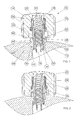
- the crown according to the invention comprises a head 14 having a side face 15 whose outer wall is provided with grooves and a front face 16 with a pattern or logo.
- This mark or logo has a non-circular geometry. It is therefore preferable that the crown, in the screwed-in position, has a determined angular orientation with respect to the box 12.
- the ring 10 is kinematically connected to a movement control rod, in particular a winding stem, via a part 18 called piston.
- a movement control rod in particular a winding stem
- the head 14 is connected to this piston 18 by connecting means comprising a first tube 20 secured to the head 14 and in which slides the piston 18, and a spring member 22 which ensures the repositioning of the rod. control in its neutral position.
- the ring 10 is screwed by means of an internal thread as described in the patent CH 454 753 .
- the first tube 20 has on its outer circumference a thread 24 (cf. Fig. 2 ) and there is provided a second tube 26, in which the first tube 20 is introduced, and comprising, on the side of the first tube 20, an internal thread 28 (cf. Fig. 2 ) arranged to cooperate with the thread 24 of the first tube 20 to allow screwing of the head 14 on the tube 26.
- the threads 24 and 28 are sized and made so that, during the screwing of the head 14 on the second tube 26 , the first tube 20 comes into mechanical abutment in said second tube 26, thus defining the final orientation of the ring relative to said second tube 26.
- the second tube 26 comprises first indexing means whose operation will be described later.
- These indexing means consist of a ring gear 30 provided on the outer periphery of the second tube 26, on the side of the box 12.
- the second tube 26 comprises on its outer periphery, above the ring gear 30, a circular flange 32, whose operation will be described later.
- the expression "above” means that the element concerned is closer to the head 14 than the other element to which it is compared.
- sealing means 34 are positioned between the head 14 and the second tube 26.
- a third tube 36 arranged to receive the second tube 26, itself receiving the first tube 20 and the piston 18.
- the third tube 36 is formed of two parts 38 and 40.
- the first part 38 is screwed into a tapped hole 42 provided in the middle of the box 12.
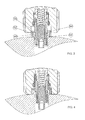
- the tube 36 could also be driven into the box 12, the hole 42 then being smooth, as shown in FIG. figure 5 .
- the third tube 36 is permanently positioned, perfectly sealed, by usual techniques, including welding or gluing. Sealing means 60 may also be placed between the end of the tube 26 and the first part 38 of the tube 36, or between the flange 32 of the tube 26 and the second part 40 of the tube 36, or between the teeth and ring gear and the tube 36.
- the second part 40 of this tube 36 protrudes from the box and has an outer shoulder 44 intended to come to rest on the build.
- the second part 40 has an external thread 46 (cf. Fig. 3 ) whose operation will be described later.
- the figure 5 represents another embodiment of the ring according to the invention according to which the third tube 36 is integrated entirely in the box 12.
- the third tube 36 comprises second indexing means cooperating with the first indexing means of the second tube 26.
- These second indexing means consist of an internal toothing 48 provided on the inner periphery of the second part 40 of the tube 36, and arranged to cooperate with the ring gear 30 of the second tube 26.
- the number of teeth of the ring gear 30 and the internal toothing 48 can vary and depend on the number of positions in which it is desired to orient the tube 26 relative to the tube 36.
- the ring gear and the teeth used in the present invention can be replaced by any equivalent means, such as gouges, grooves, or grooves, the number of these elements depending on the number of positions in which it is desired to be able to orient the tubes 26 and 36 one compared to each other.
- the third tube 36 comprises, at the top of its second portion 40, above the internal toothing 48, an internal shoulder 50 dimensioned so that the flange 32 of the second tube 26 rests on said inner shoulder 50 when the second tube 26 is placed in the third tube 36.
- a locking member 52 (cf. Fig. 3 ) arranged to block the displacement in translation of the second tube 26, in the direction of the control rod, with respect to the third tube 36.
- the locking member 52 is formed of a nut provided with a bearing surface 54 intended to abut on the flange 32 of the second tube 26.
- the bearing surface 54 has an opening whose diameter is slightly greater than that of the second tube 26, so as to introduce the nut around the second tube 26 and the scope 54 rests on the flange 32 of the tube 26.
- the nut has an internal thread 56 arranged to cooperate with the external thread 46 of the second portion 40 of the third tube 36.
- the head 14 has at its base a recess 58 arranged to receive at least partially the locking member 52 and the second portion 40 of the third tube 36.
- the box 12 which comprises a housing 62 of shape and dimensions suitable for receiving the parts 38 and 40 of the third tube 36.
Landscapes
- Physics & Mathematics (AREA)
- General Physics & Mathematics (AREA)
- Transmission Devices (AREA)
- Mutual Connection Of Rods And Tubes (AREA)
Applications Claiming Priority (1)
| Application Number | Priority Date | Filing Date | Title |
|---|---|---|---|
| CH01708/08A CH699877A1 (fr) | 2008-10-31 | 2008-10-31 | Couronne a visser et procédé d'orientation d'une telle couronne sur une boîte de montre. |
Publications (2)
| Publication Number | Publication Date |
|---|---|
| EP2182417A2 true EP2182417A2 (de) | 2010-05-05 |
| EP2182417A3 EP2182417A3 (de) | 2010-09-01 |
Family
ID=40481871
Family Applications (1)
| Application Number | Title | Priority Date | Filing Date |
|---|---|---|---|
| EP09174003A Withdrawn EP2182417A3 (de) | 2008-10-31 | 2009-10-26 | Kronrad zum Aufschrauben und Orientierungsverfahren eines solchen Kronrads auf einem Armbanduhrengehäuse |
Country Status (2)
| Country | Link |
|---|---|
| EP (1) | EP2182417A3 (de) |
| CH (1) | CH699877A1 (de) |
Cited By (9)
| Publication number | Priority date | Publication date | Assignee | Title |
|---|---|---|---|---|
| EP2385432A2 (de) | 2010-05-04 | 2011-11-09 | Rolex Sa | Uhrgehäuse |
| WO2012168243A1 (fr) * | 2011-06-08 | 2012-12-13 | Omega Sa | Dispositif pour l'orientation d'un element visse d'une piece d'horlogerie |
| CN103105768A (zh) * | 2011-11-09 | 2013-05-15 | 劳力士有限公司 | 具有方位记忆表冠的表壳 |
| ITMI20121860A1 (it) * | 2012-10-31 | 2014-05-01 | Montres Sea God Sa | Corona di orologio avente funzionalita' migliorata. |
| WO2014067743A1 (fr) | 2012-11-02 | 2014-05-08 | Omega Sa | Dispositif pour l'orientation d'un element visse d'une piece d'horlogerie |
| EP3279745A1 (de) * | 2016-08-02 | 2018-02-07 | Meco S.A. | Ausrichtbare geschraubte krone |
| EP3495896A1 (de) | 2017-12-11 | 2019-06-12 | Barigna SA | Armbanduhr, die mit einem steuerorgan des innenmechanismus ausgestattet ist |
| CN112631109A (zh) * | 2019-10-09 | 2021-04-09 | 梅科股份公司 | 可调节的拧紧表冠 |
| WO2022018608A1 (fr) | 2020-07-21 | 2022-01-27 | Manufacture Contemporaine Du Temps (Mct) Sa | Pièce horlogerie comportant un organe de commande rotatif |
Citations (2)
| Publication number | Priority date | Publication date | Assignee | Title |
|---|---|---|---|---|
| CH454753A (de) | 1965-09-09 | 1968-06-28 | Meyer & Co Ag | Aus nicht dichtendem Material bestehende Einschraubaufzugkrone für Uhren |
| WO2001040881A1 (fr) | 1999-12-02 | 2001-06-07 | Ks 22 S.A. | Procede de montage d'une couronne vissee sur une boîte de montre et boîte de montre munie d'une telle couronne |
Family Cites Families (2)
| Publication number | Priority date | Publication date | Assignee | Title |
|---|---|---|---|---|
| CH705649B1 (fr) * | 2000-02-08 | 2013-04-30 | Boninchi Sa | Dispositif permettant le réglage de l'orientation d'une couronne à vis d'une montre par rapport à la carrure de la montre. |
| DE602005006249D1 (de) * | 2005-05-24 | 2008-06-05 | Pibor Iso S A | Einschraubkrone und Montageverfahren dieser Krone auf ein Uhrgehäuse |
-
2008
- 2008-10-31 CH CH01708/08A patent/CH699877A1/fr not_active Application Discontinuation
-
2009
- 2009-10-26 EP EP09174003A patent/EP2182417A3/de not_active Withdrawn
Patent Citations (2)
| Publication number | Priority date | Publication date | Assignee | Title |
|---|---|---|---|---|
| CH454753A (de) | 1965-09-09 | 1968-06-28 | Meyer & Co Ag | Aus nicht dichtendem Material bestehende Einschraubaufzugkrone für Uhren |
| WO2001040881A1 (fr) | 1999-12-02 | 2001-06-07 | Ks 22 S.A. | Procede de montage d'une couronne vissee sur une boîte de montre et boîte de montre munie d'une telle couronne |
Cited By (26)
| Publication number | Priority date | Publication date | Assignee | Title |
|---|---|---|---|---|
| US8882342B2 (en) | 2010-05-04 | 2014-11-11 | Rolex S.A. | Watch case |
| WO2011137544A2 (fr) | 2010-05-04 | 2011-11-10 | Rolex S.A. | Boite de montre |
| EP2385432A2 (de) | 2010-05-04 | 2011-11-09 | Rolex Sa | Uhrgehäuse |
| WO2012168243A1 (fr) * | 2011-06-08 | 2012-12-13 | Omega Sa | Dispositif pour l'orientation d'un element visse d'une piece d'horlogerie |
| CN103597412B (zh) * | 2011-06-08 | 2016-02-03 | 奥米加股份有限公司 | 用于定向钟表的旋入式元件的装置 |
| US9110444B2 (en) | 2011-06-08 | 2015-08-18 | Omega Sa | Device for orientating a screwdown element for a timepiece |
| CN103597412A (zh) * | 2011-06-08 | 2014-02-19 | 奥米加股份有限公司 | 用于定向钟表的旋入式元件的装置 |
| CN103105768B (zh) * | 2011-11-09 | 2015-11-25 | 劳力士有限公司 | 具有方位记忆表冠的表壳 |
| US8740451B2 (en) | 2011-11-09 | 2014-06-03 | Rolex S.A. | Watch case including an orientation memory crown |
| JP2013101122A (ja) * | 2011-11-09 | 2013-05-23 | Rolex Sa | 向きを記憶する竜頭を備えた時計ケース |
| EP2592500A1 (de) | 2011-11-09 | 2013-05-15 | Rolex S.A. | Armbanduhrengehäuse, das ein Kronrad mit Ausrichtungsgedächtnis umfasst |
| CN103105768A (zh) * | 2011-11-09 | 2013-05-15 | 劳力士有限公司 | 具有方位记忆表冠的表壳 |
| ITMI20121860A1 (it) * | 2012-10-31 | 2014-05-01 | Montres Sea God Sa | Corona di orologio avente funzionalita' migliorata. |
| WO2014067743A1 (fr) | 2012-11-02 | 2014-05-08 | Omega Sa | Dispositif pour l'orientation d'un element visse d'une piece d'horlogerie |
| US9317014B2 (en) | 2012-11-02 | 2016-04-19 | Omega Sa | Device for the orientation of a screw-in element of a timepiece |
| US20180039229A1 (en) * | 2016-08-02 | 2018-02-08 | Meco S.A. | Screw-down orientable crown |
| EP3279745A1 (de) * | 2016-08-02 | 2018-02-07 | Meco S.A. | Ausrichtbare geschraubte krone |
| CN107678268A (zh) * | 2016-08-02 | 2018-02-09 | Meco有限公司 | 可定向的旋入式表冠 |
| KR20180015080A (ko) * | 2016-08-02 | 2018-02-12 | 매코 쏘시에떼 아노님 | 스크류-다운 배향가능 크라운 |
| US10228656B2 (en) | 2016-08-02 | 2019-03-12 | Meco S.A. | Screw-down orientable crown |
| CN107678268B (zh) * | 2016-08-02 | 2020-04-10 | Meco有限公司 | 可定向的旋入式表冠 |
| EP3495896A1 (de) | 2017-12-11 | 2019-06-12 | Barigna SA | Armbanduhr, die mit einem steuerorgan des innenmechanismus ausgestattet ist |
| CN112631109A (zh) * | 2019-10-09 | 2021-04-09 | 梅科股份公司 | 可调节的拧紧表冠 |
| EP3805872A1 (de) * | 2019-10-09 | 2021-04-14 | Meco S.A. | Ausrichtbare geschraubte krone |
| CN112631109B (zh) * | 2019-10-09 | 2022-08-02 | 梅科股份公司 | 可调节的拧紧表冠 |
| WO2022018608A1 (fr) | 2020-07-21 | 2022-01-27 | Manufacture Contemporaine Du Temps (Mct) Sa | Pièce horlogerie comportant un organe de commande rotatif |
Also Published As
| Publication number | Publication date |
|---|---|
| CH699877A1 (fr) | 2010-05-14 |
| EP2182417A3 (de) | 2010-09-01 |
Similar Documents
| Publication | Publication Date | Title |
|---|---|---|
| EP2182417A2 (de) | Kronrad zum Aufschrauben und Orientierungsverfahren eines solchen Kronrads auf einem Armbanduhrengehäuse | |
| EP2592500B1 (de) | Armbanduhrengehäuse, das ein Kronrad mit Ausrichtungsgedächtnis umfasst | |
| EP2718770B1 (de) | Vorrichtung zur ausrichtung der geschraubten aufzugskrone einer uhr | |
| EP2567292B1 (de) | Uhrgehäuse | |
| EP3451071B1 (de) | Vorrichtung mit drucktaste für uhr | |
| EP2533111B1 (de) | Vorrichtung und Verfahren zum Befestigen eines Armbanduhrelements mit regulierbarer Winkelausrichtung | |
| EP2746873B1 (de) | Modularer Zusammenbau eines Druckknopfs | |
| EP2107432B1 (de) | Steuervorrichtung mit Drücker für Uhr | |
| EP3279745B1 (de) | Ausrichtbare geschraubte krone | |
| EP2065767A1 (de) | Steuervorrichtung mit Druckschalter | |
| CH707293A2 (fr) | Couronne démontable. | |
| WO2020011512A1 (fr) | Montre pourvue d'une lunette tournante avec systeme de verrouillage de la lunette muni d'une soupape a helium integree | |
| EP2915445B1 (de) | Vorrichtung und Verfahren zum drehbaren Zusammenbau von mindestens zwei Teilen, und Einheit aus den zwei zusammengebauten Teilen | |
| EP3825778A1 (de) | Steuerkranz für uhr | |
| EP1853977B1 (de) | Blockierbarer drücker | |
| EP1727005B1 (de) | Einschraubkrone und Montageverfahren dieser Krone auf ein Uhrgehäuse | |
| CH697707A2 (fr) | Couronne a baïonnette pour remontoir de montre. | |
| EP3339966B1 (de) | Drucktaste für eine uhr | |
| EP3650951A1 (de) | Uhr, die eine verriegelungsvorrichtung eines ventils oder einer krone umfasst | |
| EP2182416A1 (de) | Einrichtung zur Positionierung und Halterung eines Bodens und Verfahren zur Positionierung und Halterung dieses Bodens auf einem Mittelteil | |
| CH716825A2 (fr) | Couronne de commande pour pièce d'horlogerie. | |
| EP3321749A1 (de) | Dichtungsfuge für uhrwerk | |
| CH718095A2 (fr) | Montre comprenant un boîtier étanche logé dans une carrure extérieure. | |
| CH705219B1 (fr) | Ensemble couronne de remontoir de montre et tube fileté, et boîtier associé. | |
| CH719814B1 (fr) | Couronne à verrouillage orienté et boite de montre comportant une telle couronne |
Legal Events
| Date | Code | Title | Description |
|---|---|---|---|
| PUAI | Public reference made under article 153(3) epc to a published international application that has entered the european phase |
Free format text: ORIGINAL CODE: 0009012 |
|
| AK | Designated contracting states |
Kind code of ref document: A2 Designated state(s): AT BE BG CH CY CZ DE DK EE ES FI FR GB GR HR HU IE IS IT LI LT LU LV MC MK MT NL NO PL PT RO SE SI SK SM TR |
|
| PUAL | Search report despatched |
Free format text: ORIGINAL CODE: 0009013 |
|
| AK | Designated contracting states |
Kind code of ref document: A3 Designated state(s): AT BE BG CH CY CZ DE DK EE ES FI FR GB GR HR HU IE IS IT LI LT LU LV MC MK MT NL NO PL PT RO SE SI SK SM TR |
|
| 17P | Request for examination filed |
Effective date: 20101001 |
|
| GRAP | Despatch of communication of intention to grant a patent |
Free format text: ORIGINAL CODE: EPIDOSNIGR1 |
|
| STAA | Information on the status of an ep patent application or granted ep patent |
Free format text: STATUS: THE APPLICATION IS DEEMED TO BE WITHDRAWN |
|
| 18D | Application deemed to be withdrawn |
Effective date: 20120605 |