EP2592500B1 - Armbanduhrengehäuse, das ein Kronrad mit Ausrichtungsgedächtnis umfasst - Google Patents
Armbanduhrengehäuse, das ein Kronrad mit Ausrichtungsgedächtnis umfasst Download PDFInfo
- Publication number
- EP2592500B1 EP2592500B1 EP12191568.0A EP12191568A EP2592500B1 EP 2592500 B1 EP2592500 B1 EP 2592500B1 EP 12191568 A EP12191568 A EP 12191568A EP 2592500 B1 EP2592500 B1 EP 2592500B1
- Authority
- EP
- European Patent Office
- Prior art keywords
- tube
- watch case
- bearing surface
- constituted
- screwed
- Prior art date
- Legal status (The legal status is an assumption and is not a legal conclusion. Google has not performed a legal analysis and makes no representation as to the accuracy of the status listed.)
- Active
Links
Images


Classifications
-
- G—PHYSICS
- G04—HOROLOGY
- G04B—MECHANICALLY-DRIVEN CLOCKS OR WATCHES; MECHANICAL PARTS OF CLOCKS OR WATCHES IN GENERAL; TIME PIECES USING THE POSITION OF THE SUN, MOON OR STARS
- G04B3/00—Normal winding of clockworks by hand or mechanically; Winding up several mainsprings or driving weights simultaneously
- G04B3/04—Rigidly-mounted keys, knobs or crowns
-
- G—PHYSICS
- G04—HOROLOGY
- G04B—MECHANICALLY-DRIVEN CLOCKS OR WATCHES; MECHANICAL PARTS OF CLOCKS OR WATCHES IN GENERAL; TIME PIECES USING THE POSITION OF THE SUN, MOON OR STARS
- G04B37/00—Cases
- G04B37/08—Hermetic sealing of openings, joints, passages or slits
- G04B37/10—Hermetic sealing of openings, joints, passages or slits of winding stems
- G04B37/103—Hermetic sealing of openings, joints, passages or slits of winding stems by screwing the crown onto the case
-
- Y—GENERAL TAGGING OF NEW TECHNOLOGICAL DEVELOPMENTS; GENERAL TAGGING OF CROSS-SECTIONAL TECHNOLOGIES SPANNING OVER SEVERAL SECTIONS OF THE IPC; TECHNICAL SUBJECTS COVERED BY FORMER USPC CROSS-REFERENCE ART COLLECTIONS [XRACs] AND DIGESTS
- Y10—TECHNICAL SUBJECTS COVERED BY FORMER USPC
- Y10T—TECHNICAL SUBJECTS COVERED BY FORMER US CLASSIFICATION
- Y10T29/00—Metal working
- Y10T29/49—Method of mechanical manufacture
- Y10T29/49579—Watch or clock making
Definitions
- the invention relates to a watch case having a ring having a front face provided with a distinctive sign, this ring having the particularity of always returning to its original orientation after unscrewing and then screwing.
- the invention also relates to a method of mounting such a watch case.
- the invention also relates to a timepiece, in particular a watch, in particular a wristwatch, comprising such a box.
- the invention also relates to a box obtained by implementing the mounting method.
- the outer face of the outer part of the crown has a distinctive sign, to be able to guarantee that the distinctive sign is in a given angular orientation relative to the longitudinal axis of the tube. of the watch case to which the crown is screwed. Otherwise, the angular position of the distinctive sign is random.
- the first tube is connected to the ring and is screwed to the second tube, the third tube is arranged to receive the second tube, the second tube and the third tube comprise indexing means.
- the third tube has an internal toothing provided on the inner periphery and arranged to cooperate with a ring gear of the second tube.
- the second tube and the third tube are held locked in translation by a ring and form a subassembly having an adjustable thread on which the crown associated with the first tube is screwed.
- the angular orientation is fixed once and for all and is directly related to the number of teeth present on the second tube and the third tube, and the number of indexing positions is necessarily limited because of the small diameters of these tubes.
- this solution requires three tubes and is difficult to set up.
- the crown and the tubes may be detached from the watch case if too much torque is applied to the crown.
- This international application relates to a watch case comprising a control ring consisting of two parts, namely, an inner portion and an outer portion, the latter to be maintained in the inner portion by a clamping ring.
- the main purpose of the invention is to provide a watch case that is at least as satisfactory as that described in the aforementioned international application, while having an even smaller number of components.
- a mounting method is defined by claim 13.
- a timepiece is defined by claim 14.
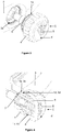
- a first embodiment of the invention is shown in the Figures 1 to 6 .
- the watch case according to the invention comprises a middle part 3 on which is mounted in a through-hole pierced in the middle band, a first tube 1.
- the rotation of the latter is prevented by its toothing which is clearly visible on the figure 2 , located on a part of its periphery and whose teeth which are distributed circumferentially and each extend axially, are engaged axially between the teeth of a toothing 3a which is clearly visible on the figure 3 and which is made by broaching in the hole of the middle part 3, the outer side thereof.
- the axial blocking of the first tube 1 relative to the middle part 3 is achieved by virtue of an internal shoulder forming a first bearing surface 1c on which a second bearing surface 2c is pressed, formed by an external shoulder complementary to a second tube. 2. It is screwed fully into the middle part 3 so as to press both the inner axial end of the first tube 1 against an annular seal 7 and an abutment surface 1d ( figure 4 ) against a stop surface 3d provided in the hole of the middle part 3.
- the axial locking of the first tube 1 relative to the middle part 3 is thus ensured by the cooperation, in particular the cooperation by obstacle, of a stop surface 1d and a stop surface 3d, in particular provided on the caseband 3.
- the axial blocking of the first tube in the other direction is ensured by the cooperation, in particular the cooperation by obstacle or contact, the first bearing surface 1c with the second support surface 2c.
- the screwing of the second tube 2 is preferably carried out using a special tool which is shaped to engage with a visible second toothing on the figure 5 and provided at the outer axial end of the second tube 2.
- the first tube further comprises, over a portion of its periphery, a thread 1b cooperating with a tapping 4b formed in an annular recess provided in the cape 4 of a control ring C.
- a distinctive sign S such as a mark or a logo.
- control ring C inside the control ring C comprises, in the center of the aforementioned annular recess, a barrel 5 which is connected to the movement of the watch by known means and which is housed and guided axially, sliding inside. the second tube 2 (cf. figure 1 ).
- control crown C will keep its orientation, in that later, after each of unscrewing and screwing, the sign S will be correctly oriented.
- a toothing 2e is provided on the inner or outer end of the second tube 2, only a qualified watchmaker equipped with a suitable tool can unscrew the second tube 2.
- annular seal 10 is disposed in an annular groove formed at the outer periphery of the first tube 1 on which is formed the thread 1b.
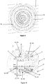
- the toothing 3a ' performed here by machining, comprises a number of teeth (three in this case) lower than that of the toothing 3a visible in particular on the figure 3 .
- a toothing 3a has been executed on a ring 6 which has been secured by driving (or any other means appropriate) in the hole of the middle part 3, the latter then having a recess of a diameter greater than that of the first embodiment of the invention.
- abutment surface 3d has also been formed in the ring 6.
- the axial locking of the first tube 1 relative to the middle part 3 is therefore ensured by the cooperation, in particular the cooperation by obstacle, of a stop surface 1d and a stop surface 3d ', in particular provided on the ring 6.
- the axial locking of the first tube in the other direction is provided by the cooperation, including cooperation by obstacle or contact, the first bearing surface 1c with the second support surface 2c.
- the second tube 2 can be fixed differently, for example by driving.
- the geometry of the tube 2 is shaped to allow its disassembly of the middle part, for example with the addition of a groove.
- the first and second indexing means (1a, 3a, 3a ', 3a ") shown in the aforementioned embodiments are not embodied by the bias of teeth which are distributed circumferentially and each extend axially on their respective member. It is also quite conceivable to achieve the same effects through circumferentially distributed and circumferentially extending edge teeth on their respective members.
- annular seals in the exemplary embodiments is optimized to ensure the sealing of the watch case.
- Those skilled in the art will be able to adapt the arrangement and / or the number of these joints according to the requirements and the design choices.
- An embodiment of a timepiece according to the invention may advantageously comprise a watch case according to one of the embodiments and variants described above.
- distinctive sign means any visible element of the crown to distinguish an orientation of the ring about its axis of rotation. The knurling or splines of the crown may be excluded from such an element.
- distinctive sign means any visible element of the crown having the consequence that the crown is not a form of revolution.
- a distinctive sign may include a marking of the crown, even if this marking is made without substantial contribution or removal of material to the crown.
Landscapes
- Physics & Mathematics (AREA)
- General Physics & Mathematics (AREA)
- Electric Clocks (AREA)
- Adornments (AREA)
- Mutual Connection Of Rods And Tubes (AREA)
- Electromechanical Clocks (AREA)
Claims (14)
- Uhrengehäuse, umfassend:- einen Gehäusering (3),- ein erstes Rohr (1) ausgestattet mit ersten Indexierungsmitteln (1a),- ein Steuerkronrad (C) umfassend:- einen Mantel (4), welcher auf der Stirnseite (4') ein Kennzeichen (S) trägt und- eine Hülse (5), welche dazu vorgesehen ist, mit dem Uhrwerk verbunden zu werden,- ein zweites Rohr (2), welches dazu vorgesehen ist, am Gehäusering (3) befestigt zu werden und die Hülse (5) aufzunehmen,- wobei das Steuerkronrad (C) und das erste Rohr (1) jeweils Schraubmittel (1b, 4b) umfassend, die die Verschraubung des einen auf dem anderen ermöglichen;dadurch gekennzeichnet, dass:- zweite, fest mit dem Gehäusering (3) verbundene Indexierungsmittel (3a, 3a', 3a") vorgesehen sind, um mit den ersten Indexierungsmitteln (1a) des ersten Rohrs (1) zusammenzuwirken und- das erste Rohr (1) und das zweite Rohr (2) derart geformt sind, dass die Befestigung des zweiten Rohrs (2) am Gehäusering (3) die axiale Feststellung des ersten Rohrs (1) im Verhältnis zum Gehäusering (3) sicherstellt, wobei eine Anlagefläche (1d) des ersten Rohrs (1) mit einer Sperrfläche (3d; 3d') des Gehäuserings (3) oder mit einer Sperrfläche (3d') eines am Gehäusering befestigten oder mit ihm verbundenen Rings (6) in Anlage kommt.
- Uhrengehäuse gemäß Anspruch 1, bei welchem das erste Rohr (1) eine erste Lageroberfläche (1c) umfasst, die in Anlage mit einer Anlagefläche (2c) kommt, welche auf dem zweiten Rohr (2) vorgesehen ist.
- Uhrengehäuse gemäß Anspruch 2, bei welchem die erste Anlagefläche (1c) durch eine Innenschulter gebildet ist und die zweite Anlagefläche (2c) durch eine Außenschulter (2c) gebildet ist.
- Uhrengehäuse gemäß Anspruch 2 oder Anspruch 3, bei welchem das zweite Rohr (2) dazu vorgesehen ist, in den Gehäusering (3) eingepresst zu werden, wobei die zweite Anlagefläche (2c) zur Anlage gegen die erste Anlagefläche (1c) kommt.
- Uhrengehäuse gemäß Anspruch 2 oder Anspruch 3, bei welchem das zweite Rohr (2) dazu vorgesehen ist, in den Gehäusering (3) eingeschraubt zu werden, wobei die zweite Anlagefläche (2c) zur Anlage gegen die erste Anlagefläche (1c) kommt.
- Uhrengehäuse gemäß Anspruch 5, bei welchem das zweite Rohr (2) Mittel (2e) umfasst, die es ihm erlauben mit einem geeigneten Werkzeug ein- oder ausgeschraubt zu werden.
- Uhrengehäuse gemäß Anspruch 6, bei welchem die Mittel (2e) als Zahnung ausgebildet sind, die an einem Ende auf der Seite der Steuerkrone (4) vorgesehen ist.
- Uhrengehäuse gemäß einem der Ansprüche 1 bis 7, bei welchem die ersten und die zweiten Indexierungsmittel (1a, 3a, 3a', 3a") durch Zahnungen gebildet sind, die so geformt sind, dass sie axial ineinander greifen.
- Uhrengehäuse gemäß einem der Ansprüche 1 bis 8, bei welchem die zweiten Indexierungsmittel (3a, 3a') am Gehäusering (3) vorgesehen sind.
- Uhrengehäuse gemäß einem der Ansprüche 1 bis 7, bei welchem die zweiten Indexierungsmittel (3a") auf einem Ring (6) angeordnet sind, der fest mit dem Gehäusering (3) verbunden ist.
- Uhrengehäuse gemäß einem der Ansprüche 1 bis 10, bei welchem die genannte Anlagefläche (1d) des ersten Rohrs (1) dazu vorgesehen ist, in Anlage mit der genannten Sperrfläche (3d, 3d') zu kommen, welche in dem Gehäusering (3) vorgesehen ist.
- Uhrengehäuse gemäß einem der Ansprüche 1 bis 11, bei welchem die Schraubmittel (1b) des ersten Rohrs (1) als ein Gewinde ausgebildet sind und die Schraubmittel (4b) des Steuerkronrads (C) als Innengewinde ausgebildet sind, welches in eine ringförmige Ausnehmung geformt ist, die in dem Steuerkronrad (C) vorgesehen ist.
- Montageverfahren für ein Uhrengehäuse gemäß einem der Ansprüche 1 bis 12, umfassend die folgenden Schritte:- man schraubt den Mantel (4) des Steuerkronrads (C) auf dem ersten Rohr (1) fest,- man richtet nach einer vorgegebenen Weise das Kennzeichen (S) der Stirnseite (4') des Mantels (4) im Verhältnis zum Gehäusering (3) aus,- man führt das freie Ende des ersten Rohrs (1) in den Gehäusering (3) ein, indem man die ersten Indexierungsmittel des ersten Teils (1), insbesondere eine Zahnung (1a) axial in die zweiten Indexierungsmittel, die fest mit dem Gehäusering (3) verbunden sind, insbesondere in eine Zahnung (3a, 3a', 3a") gleiten lässt,- man schraubt den Mantel (4) vom ersten Rohr (1) ab und belässt letzteres im Gehäusering (3),- man führt das zweite Rohr (2) in das erste Rohr (1) ein,- man schraubt das zweite Rohr (2) so weit, bis es durch die Anlage der Anlagefläche (1d) des ersten Rohrs an die Sperrfläche (3d, 3d') des Gehäuserings (3) oder an die Sperrfläche (3d') eines Rings (6), der am Gehäusering (3) befestigt oder mit ihm verbunden ist, blockiert ist; und- man schraubt den Mantel (4) auf dem ersten Rohr (1) fest.
- Uhr, insbesondere Armbanduhr, umfassend ein Uhrengehäuse gemäß einem der Ansprüche 1 bis 12.
Priority Applications (1)
| Application Number | Priority Date | Filing Date | Title |
|---|---|---|---|
| EP12191568.0A EP2592500B1 (de) | 2011-11-09 | 2012-11-07 | Armbanduhrengehäuse, das ein Kronrad mit Ausrichtungsgedächtnis umfasst |
Applications Claiming Priority (2)
| Application Number | Priority Date | Filing Date | Title |
|---|---|---|---|
| EP11405355 | 2011-11-09 | ||
| EP12191568.0A EP2592500B1 (de) | 2011-11-09 | 2012-11-07 | Armbanduhrengehäuse, das ein Kronrad mit Ausrichtungsgedächtnis umfasst |
Publications (2)
| Publication Number | Publication Date |
|---|---|
| EP2592500A1 EP2592500A1 (de) | 2013-05-15 |
| EP2592500B1 true EP2592500B1 (de) | 2019-01-16 |
Family
ID=47088763
Family Applications (1)
| Application Number | Title | Priority Date | Filing Date |
|---|---|---|---|
| EP12191568.0A Active EP2592500B1 (de) | 2011-11-09 | 2012-11-07 | Armbanduhrengehäuse, das ein Kronrad mit Ausrichtungsgedächtnis umfasst |
Country Status (4)
| Country | Link |
|---|---|
| US (1) | US8740451B2 (de) |
| EP (1) | EP2592500B1 (de) |
| JP (1) | JP6214145B2 (de) |
| CN (1) | CN103105768B (de) |
Families Citing this family (19)
| Publication number | Priority date | Publication date | Assignee | Title |
|---|---|---|---|---|
| JP3047333B2 (ja) | 1990-02-28 | 2000-05-29 | 東芝ライテック株式会社 | 遠隔制御用スイッチ装置および遠隔監視制御システム |
| JP5725065B2 (ja) * | 2013-03-21 | 2015-05-27 | カシオ計算機株式会社 | スイッチ装置および時計 |
| USD756805S1 (en) * | 2013-10-17 | 2016-05-24 | La Montre Hermes S.A. | Watch case |
| USD733582S1 (en) * | 2013-12-20 | 2015-07-07 | Rolex Watch U.S.A., Inc. | Watch case |
| CN104698811B (zh) * | 2015-03-24 | 2017-04-26 | 惠州Tcl移动通信有限公司 | 表壳组件及手表 |
| EP3279745B1 (de) * | 2016-08-02 | 2023-06-14 | Meco S.A. | Ausrichtbare geschraubte krone |
| EP3287855B1 (de) * | 2016-08-26 | 2019-05-01 | Meco S.A. | Einstellkrone für uhr |
| US10324538B2 (en) | 2016-08-30 | 2019-06-18 | Garmin Switzerland Gmbh | Dynamic watch user interface |
| FR3062728B1 (fr) * | 2017-02-03 | 2019-03-22 | Cheval Freres | Tube fixe indexe pour boitier de montre et ensemble le comportant |
| AU201811024S (en) * | 2017-10-17 | 2018-03-15 | Omega Sa Omega Ag Omega Ltd | Watch crown |
| JP6919645B2 (ja) * | 2018-12-18 | 2021-08-18 | カシオ計算機株式会社 | スイッチ装置および時計 |
| CN109739908A (zh) * | 2018-12-28 | 2019-05-10 | 芜湖哈特机器人产业技术研究院有限公司 | 一种导管信息查询管理系统 |
| EP3805870B1 (de) * | 2019-10-09 | 2025-11-26 | Meco S.A. | Armbanduhrgehäuse mit ausrichtbarer geschraubter krone |
| EP3805873B1 (de) | 2019-10-09 | 2023-12-06 | Meco S.A. | Ausrichtbare geschraubte krone |
| EP3805869B1 (de) * | 2019-10-09 | 2025-12-24 | Meco S.A. | Geschraubte krone |
| EP3805872B1 (de) * | 2019-10-09 | 2025-11-26 | Meco S.A. | Ausrichtbare geschraubte krone |
| EP3805874B1 (de) | 2019-10-09 | 2023-12-27 | Meco S.A. | Ausrichtbare geschraubte krone |
| EP4024137B1 (de) * | 2020-12-31 | 2023-08-23 | Meco S.A. | Steuervorrichtung einer uhr |
| JP1764073S (ja) * | 2023-03-14 | 2024-02-21 | 腕時計の竜頭 |
Family Cites Families (10)
| Publication number | Priority date | Publication date | Assignee | Title |
|---|---|---|---|---|
| CH682968B5 (fr) * | 1992-02-12 | 1994-06-30 | Rolex Montres | Procédé de fabrication d'un joint et joint pour dispositif de commande étanche pour montre obtenu selon ce procédé. |
| CH705218B1 (fr) * | 1999-12-02 | 2013-01-15 | Ks 22 S A | Procédé de montage d'une couronne vissée sur une boîte de montre. |
| US20020067665A1 (en) * | 2000-12-01 | 2002-06-06 | Roger Ecoffet | Method for assembling a screwed crown on a watch case |
| EP1411401A1 (de) * | 2002-10-17 | 2004-04-21 | Ks 22 Sa | Geschraubte Krone für Uhren |
| JP4040996B2 (ja) * | 2003-03-10 | 2008-01-30 | セイコーインスツル株式会社 | 携帯時計 |
| WO2005038538A1 (fr) * | 2003-10-21 | 2005-04-28 | Richemont International Sa | Dispositif de commande a couronne-poussoir pour montre |
| WO2005040942A1 (fr) * | 2003-10-24 | 2005-05-06 | Richemont International Sa | Dispositif de commande à couronne débrayable pour montre |
| DE602007006799D1 (de) * | 2007-08-30 | 2010-07-08 | Eta Sa Mft Horlogere Suisse | Uhr, die mit einer Funktionsanzeige ausgestattet ist |
| CH699877A1 (fr) | 2008-10-31 | 2010-05-14 | Pibor Iso S A | Couronne a visser et procédé d'orientation d'une telle couronne sur une boîte de montre. |
| EP2385432A2 (de) | 2010-05-04 | 2011-11-09 | Rolex Sa | Uhrgehäuse |
-
2012
- 2012-11-07 EP EP12191568.0A patent/EP2592500B1/de active Active
- 2012-11-08 JP JP2012245882A patent/JP6214145B2/ja not_active Expired - Fee Related
- 2012-11-08 CN CN201210558441.4A patent/CN103105768B/zh not_active Expired - Fee Related
- 2012-11-08 US US13/672,301 patent/US8740451B2/en active Active
Non-Patent Citations (1)
| Title |
|---|
| None * |
Also Published As
| Publication number | Publication date |
|---|---|
| EP2592500A1 (de) | 2013-05-15 |
| CN103105768B (zh) | 2015-11-25 |
| JP2013101122A (ja) | 2013-05-23 |
| JP6214145B2 (ja) | 2017-10-18 |
| US20130114383A1 (en) | 2013-05-09 |
| CN103105768A (zh) | 2013-05-15 |
| US8740451B2 (en) | 2014-06-03 |
Similar Documents
| Publication | Publication Date | Title |
|---|---|---|
| EP2592500B1 (de) | Armbanduhrengehäuse, das ein Kronrad mit Ausrichtungsgedächtnis umfasst | |
| EP2718770B1 (de) | Vorrichtung zur ausrichtung der geschraubten aufzugskrone einer uhr | |
| EP2746873B1 (de) | Modularer Zusammenbau eines Druckknopfs | |
| EP1651899B1 (de) | Verriegelungsvorrichtung und damit versehenes leitungsanschlussstück | |
| EP2533111B1 (de) | Vorrichtung und Verfahren zum Befestigen eines Armbanduhrelements mit regulierbarer Winkelausrichtung | |
| EP2746870B1 (de) | Abnehmbares Kronrad | |
| EP2107432B1 (de) | Steuervorrichtung mit Drücker für Uhr | |
| EP2338776A1 (de) | Zweiradlenkkopf mit Bolzen und Zweirad mit einem solchen Lenkkopf | |
| EP2915445B1 (de) | Vorrichtung und Verfahren zum drehbaren Zusammenbau von mindestens zwei Teilen, und Einheit aus den zwei zusammengebauten Teilen | |
| EP1151357B1 (de) | Verfahren zum montieren einer geschraubten krone auf einem uhrengehäuse und mit einer solchen krone versehenes uhrengehäuse | |
| EP2182417A2 (de) | Kronrad zum Aufschrauben und Orientierungsverfahren eines solchen Kronrads auf einem Armbanduhrengehäuse | |
| EP0402198B1 (de) | Verriegelungsmutter | |
| EP1890203B1 (de) | Armbanduhrgehäuse, das einen Boden umfasst, und Verfahren zur Befestigung eines Bodens auf ein Armbanduhrgehäuse | |
| EP2643736B1 (de) | Uhr mit einem starren gehäuse und verfahren zum anbringen des gehäuses | |
| EP1727005B1 (de) | Einschraubkrone und Montageverfahren dieser Krone auf ein Uhrgehäuse | |
| CH700722B1 (fr) | Appareil horaire portable. | |
| EP3339966B1 (de) | Drucktaste für eine uhr | |
| FR3032638A1 (fr) | Mandrin porte-foret | |
| CH716825A2 (fr) | Couronne de commande pour pièce d'horlogerie. | |
| EP4123391B1 (de) | Uhrenkomponente zur befestigung auf einer welle und verfahren | |
| EP3492995A1 (de) | Kranzsystem für uhr | |
| CH719814A2 (fr) | Couronne à verrouillage orienté et boite de montre comportant une telle couronne. | |
| CH707191A2 (fr) | Assemblage modulaire d'un poussoir. | |
| EP4174583A1 (de) | Steuervorrichtung für eine uhr | |
| FR3033513A1 (fr) | Couteau a lame articulee pourvu d’une virole de blocage amelioree |
Legal Events
| Date | Code | Title | Description |
|---|---|---|---|
| PUAI | Public reference made under article 153(3) epc to a published international application that has entered the european phase |
Free format text: ORIGINAL CODE: 0009012 |
|
| AK | Designated contracting states |
Kind code of ref document: A1 Designated state(s): AL AT BE BG CH CY CZ DE DK EE ES FI FR GB GR HR HU IE IS IT LI LT LU LV MC MK MT NL NO PL PT RO RS SE SI SK SM TR |
|
| AX | Request for extension of the european patent |
Extension state: BA ME |
|
| 17P | Request for examination filed |
Effective date: 20131106 |
|
| RBV | Designated contracting states (corrected) |
Designated state(s): AL AT BE BG CH CY CZ DE DK EE ES FI FR GB GR HR HU IE IS IT LI LT LU LV MC MK MT NL NO PL PT RO RS SE SI SK SM TR |
|
| GRAP | Despatch of communication of intention to grant a patent |
Free format text: ORIGINAL CODE: EPIDOSNIGR1 |
|
| STAA | Information on the status of an ep patent application or granted ep patent |
Free format text: STATUS: GRANT OF PATENT IS INTENDED |
|
| INTG | Intention to grant announced |
Effective date: 20180727 |
|
| GRAS | Grant fee paid |
Free format text: ORIGINAL CODE: EPIDOSNIGR3 |
|
| GRAA | (expected) grant |
Free format text: ORIGINAL CODE: 0009210 |
|
| STAA | Information on the status of an ep patent application or granted ep patent |
Free format text: STATUS: THE PATENT HAS BEEN GRANTED |
|
| AK | Designated contracting states |
Kind code of ref document: B1 Designated state(s): AL AT BE BG CH CY CZ DE DK EE ES FI FR GB GR HR HU IE IS IT LI LT LU LV MC MK MT NL NO PL PT RO RS SE SI SK SM TR |
|
| REG | Reference to a national code |
Ref country code: GB Ref legal event code: FG4D Free format text: NOT ENGLISH |
|
| REG | Reference to a national code |
Ref country code: CH Ref legal event code: EP |
|
| REG | Reference to a national code |
Ref country code: IE Ref legal event code: FG4D Free format text: LANGUAGE OF EP DOCUMENT: FRENCH |
|
| REG | Reference to a national code |
Ref country code: DE Ref legal event code: R096 Ref document number: 602012055953 Country of ref document: DE |
|
| REG | Reference to a national code |
Ref country code: CH Ref legal event code: NV Representative=s name: MOINAS AND SAVOYE SARL, CH Ref country code: AT Ref legal event code: REF Ref document number: 1090168 Country of ref document: AT Kind code of ref document: T Effective date: 20190215 |
|
| REG | Reference to a national code |
Ref country code: NL Ref legal event code: MP Effective date: 20190116 |
|
| REG | Reference to a national code |
Ref country code: LT Ref legal event code: MG4D |
|
| PG25 | Lapsed in a contracting state [announced via postgrant information from national office to epo] |
Ref country code: NL Free format text: LAPSE BECAUSE OF FAILURE TO SUBMIT A TRANSLATION OF THE DESCRIPTION OR TO PAY THE FEE WITHIN THE PRESCRIBED TIME-LIMIT Effective date: 20190116 |
|
| REG | Reference to a national code |
Ref country code: AT Ref legal event code: MK05 Ref document number: 1090168 Country of ref document: AT Kind code of ref document: T Effective date: 20190116 |
|
| PG25 | Lapsed in a contracting state [announced via postgrant information from national office to epo] |
Ref country code: PT Free format text: LAPSE BECAUSE OF FAILURE TO SUBMIT A TRANSLATION OF THE DESCRIPTION OR TO PAY THE FEE WITHIN THE PRESCRIBED TIME-LIMIT Effective date: 20190516 Ref country code: ES Free format text: LAPSE BECAUSE OF FAILURE TO SUBMIT A TRANSLATION OF THE DESCRIPTION OR TO PAY THE FEE WITHIN THE PRESCRIBED TIME-LIMIT Effective date: 20190116 Ref country code: SE Free format text: LAPSE BECAUSE OF FAILURE TO SUBMIT A TRANSLATION OF THE DESCRIPTION OR TO PAY THE FEE WITHIN THE PRESCRIBED TIME-LIMIT Effective date: 20190116 Ref country code: NO Free format text: LAPSE BECAUSE OF FAILURE TO SUBMIT A TRANSLATION OF THE DESCRIPTION OR TO PAY THE FEE WITHIN THE PRESCRIBED TIME-LIMIT Effective date: 20190416 Ref country code: FI Free format text: LAPSE BECAUSE OF FAILURE TO SUBMIT A TRANSLATION OF THE DESCRIPTION OR TO PAY THE FEE WITHIN THE PRESCRIBED TIME-LIMIT Effective date: 20190116 Ref country code: LT Free format text: LAPSE BECAUSE OF FAILURE TO SUBMIT A TRANSLATION OF THE DESCRIPTION OR TO PAY THE FEE WITHIN THE PRESCRIBED TIME-LIMIT Effective date: 20190116 Ref country code: PL Free format text: LAPSE BECAUSE OF FAILURE TO SUBMIT A TRANSLATION OF THE DESCRIPTION OR TO PAY THE FEE WITHIN THE PRESCRIBED TIME-LIMIT Effective date: 20190116 |
|
| PG25 | Lapsed in a contracting state [announced via postgrant information from national office to epo] |
Ref country code: BG Free format text: LAPSE BECAUSE OF FAILURE TO SUBMIT A TRANSLATION OF THE DESCRIPTION OR TO PAY THE FEE WITHIN THE PRESCRIBED TIME-LIMIT Effective date: 20190416 Ref country code: IS Free format text: LAPSE BECAUSE OF FAILURE TO SUBMIT A TRANSLATION OF THE DESCRIPTION OR TO PAY THE FEE WITHIN THE PRESCRIBED TIME-LIMIT Effective date: 20190516 Ref country code: HR Free format text: LAPSE BECAUSE OF FAILURE TO SUBMIT A TRANSLATION OF THE DESCRIPTION OR TO PAY THE FEE WITHIN THE PRESCRIBED TIME-LIMIT Effective date: 20190116 Ref country code: GR Free format text: LAPSE BECAUSE OF FAILURE TO SUBMIT A TRANSLATION OF THE DESCRIPTION OR TO PAY THE FEE WITHIN THE PRESCRIBED TIME-LIMIT Effective date: 20190417 Ref country code: LV Free format text: LAPSE BECAUSE OF FAILURE TO SUBMIT A TRANSLATION OF THE DESCRIPTION OR TO PAY THE FEE WITHIN THE PRESCRIBED TIME-LIMIT Effective date: 20190116 Ref country code: RS Free format text: LAPSE BECAUSE OF FAILURE TO SUBMIT A TRANSLATION OF THE DESCRIPTION OR TO PAY THE FEE WITHIN THE PRESCRIBED TIME-LIMIT Effective date: 20190116 |
|
| REG | Reference to a national code |
Ref country code: DE Ref legal event code: R097 Ref document number: 602012055953 Country of ref document: DE |
|
| PG25 | Lapsed in a contracting state [announced via postgrant information from national office to epo] |
Ref country code: IT Free format text: LAPSE BECAUSE OF FAILURE TO SUBMIT A TRANSLATION OF THE DESCRIPTION OR TO PAY THE FEE WITHIN THE PRESCRIBED TIME-LIMIT Effective date: 20190116 Ref country code: RO Free format text: LAPSE BECAUSE OF FAILURE TO SUBMIT A TRANSLATION OF THE DESCRIPTION OR TO PAY THE FEE WITHIN THE PRESCRIBED TIME-LIMIT Effective date: 20190116 Ref country code: CZ Free format text: LAPSE BECAUSE OF FAILURE TO SUBMIT A TRANSLATION OF THE DESCRIPTION OR TO PAY THE FEE WITHIN THE PRESCRIBED TIME-LIMIT Effective date: 20190116 Ref country code: AT Free format text: LAPSE BECAUSE OF FAILURE TO SUBMIT A TRANSLATION OF THE DESCRIPTION OR TO PAY THE FEE WITHIN THE PRESCRIBED TIME-LIMIT Effective date: 20190116 Ref country code: DK Free format text: LAPSE BECAUSE OF FAILURE TO SUBMIT A TRANSLATION OF THE DESCRIPTION OR TO PAY THE FEE WITHIN THE PRESCRIBED TIME-LIMIT Effective date: 20190116 Ref country code: EE Free format text: LAPSE BECAUSE OF FAILURE TO SUBMIT A TRANSLATION OF THE DESCRIPTION OR TO PAY THE FEE WITHIN THE PRESCRIBED TIME-LIMIT Effective date: 20190116 Ref country code: AL Free format text: LAPSE BECAUSE OF FAILURE TO SUBMIT A TRANSLATION OF THE DESCRIPTION OR TO PAY THE FEE WITHIN THE PRESCRIBED TIME-LIMIT Effective date: 20190116 Ref country code: SK Free format text: LAPSE BECAUSE OF FAILURE TO SUBMIT A TRANSLATION OF THE DESCRIPTION OR TO PAY THE FEE WITHIN THE PRESCRIBED TIME-LIMIT Effective date: 20190116 |
|
| PLBE | No opposition filed within time limit |
Free format text: ORIGINAL CODE: 0009261 |
|
| STAA | Information on the status of an ep patent application or granted ep patent |
Free format text: STATUS: NO OPPOSITION FILED WITHIN TIME LIMIT |
|
| PG25 | Lapsed in a contracting state [announced via postgrant information from national office to epo] |
Ref country code: SM Free format text: LAPSE BECAUSE OF FAILURE TO SUBMIT A TRANSLATION OF THE DESCRIPTION OR TO PAY THE FEE WITHIN THE PRESCRIBED TIME-LIMIT Effective date: 20190116 |
|
| 26N | No opposition filed |
Effective date: 20191017 |
|
| PG25 | Lapsed in a contracting state [announced via postgrant information from national office to epo] |
Ref country code: SI Free format text: LAPSE BECAUSE OF FAILURE TO SUBMIT A TRANSLATION OF THE DESCRIPTION OR TO PAY THE FEE WITHIN THE PRESCRIBED TIME-LIMIT Effective date: 20190116 |
|
| PG25 | Lapsed in a contracting state [announced via postgrant information from national office to epo] |
Ref country code: TR Free format text: LAPSE BECAUSE OF FAILURE TO SUBMIT A TRANSLATION OF THE DESCRIPTION OR TO PAY THE FEE WITHIN THE PRESCRIBED TIME-LIMIT Effective date: 20190116 |
|
| PG25 | Lapsed in a contracting state [announced via postgrant information from national office to epo] |
Ref country code: LU Free format text: LAPSE BECAUSE OF NON-PAYMENT OF DUE FEES Effective date: 20191107 Ref country code: MC Free format text: LAPSE BECAUSE OF FAILURE TO SUBMIT A TRANSLATION OF THE DESCRIPTION OR TO PAY THE FEE WITHIN THE PRESCRIBED TIME-LIMIT Effective date: 20190116 |
|
| REG | Reference to a national code |
Ref country code: BE Ref legal event code: MM Effective date: 20191130 |
|
| PG25 | Lapsed in a contracting state [announced via postgrant information from national office to epo] |
Ref country code: IE Free format text: LAPSE BECAUSE OF NON-PAYMENT OF DUE FEES Effective date: 20191107 |
|
| PG25 | Lapsed in a contracting state [announced via postgrant information from national office to epo] |
Ref country code: BE Free format text: LAPSE BECAUSE OF NON-PAYMENT OF DUE FEES Effective date: 20191130 |
|
| PG25 | Lapsed in a contracting state [announced via postgrant information from national office to epo] |
Ref country code: CY Free format text: LAPSE BECAUSE OF FAILURE TO SUBMIT A TRANSLATION OF THE DESCRIPTION OR TO PAY THE FEE WITHIN THE PRESCRIBED TIME-LIMIT Effective date: 20190116 |
|
| PG25 | Lapsed in a contracting state [announced via postgrant information from national office to epo] |
Ref country code: HU Free format text: LAPSE BECAUSE OF FAILURE TO SUBMIT A TRANSLATION OF THE DESCRIPTION OR TO PAY THE FEE WITHIN THE PRESCRIBED TIME-LIMIT; INVALID AB INITIO Effective date: 20121107 Ref country code: MT Free format text: LAPSE BECAUSE OF FAILURE TO SUBMIT A TRANSLATION OF THE DESCRIPTION OR TO PAY THE FEE WITHIN THE PRESCRIBED TIME-LIMIT Effective date: 20190116 |
|
| PG25 | Lapsed in a contracting state [announced via postgrant information from national office to epo] |
Ref country code: MK Free format text: LAPSE BECAUSE OF FAILURE TO SUBMIT A TRANSLATION OF THE DESCRIPTION OR TO PAY THE FEE WITHIN THE PRESCRIBED TIME-LIMIT Effective date: 20190116 |
|
| PGFP | Annual fee paid to national office [announced via postgrant information from national office to epo] |
Ref country code: GB Payment date: 20221121 Year of fee payment: 11 Ref country code: FR Payment date: 20221122 Year of fee payment: 11 Ref country code: DE Payment date: 20220624 Year of fee payment: 11 |
|
| P01 | Opt-out of the competence of the unified patent court (upc) registered |
Effective date: 20230528 |
|
| REG | Reference to a national code |
Ref country code: DE Ref legal event code: R119 Ref document number: 602012055953 Country of ref document: DE |
|
| GBPC | Gb: european patent ceased through non-payment of renewal fee |
Effective date: 20231107 |
|
| PG25 | Lapsed in a contracting state [announced via postgrant information from national office to epo] |
Ref country code: DE Free format text: LAPSE BECAUSE OF NON-PAYMENT OF DUE FEES Effective date: 20240601 |
|
| PG25 | Lapsed in a contracting state [announced via postgrant information from national office to epo] |
Ref country code: GB Free format text: LAPSE BECAUSE OF NON-PAYMENT OF DUE FEES Effective date: 20231107 |
|
| PG25 | Lapsed in a contracting state [announced via postgrant information from national office to epo] |
Ref country code: FR Free format text: LAPSE BECAUSE OF NON-PAYMENT OF DUE FEES Effective date: 20231130 |
|
| PG25 | Lapsed in a contracting state [announced via postgrant information from national office to epo] |
Ref country code: GB Free format text: LAPSE BECAUSE OF NON-PAYMENT OF DUE FEES Effective date: 20231107 Ref country code: FR Free format text: LAPSE BECAUSE OF NON-PAYMENT OF DUE FEES Effective date: 20231130 Ref country code: DE Free format text: LAPSE BECAUSE OF NON-PAYMENT OF DUE FEES Effective date: 20240601 |
|
| REG | Reference to a national code |
Ref country code: CH Ref legal event code: U11 Free format text: ST27 STATUS EVENT CODE: U-0-0-U10-U11 (AS PROVIDED BY THE NATIONAL OFFICE) Effective date: 20251201 |
|
| PGFP | Annual fee paid to national office [announced via postgrant information from national office to epo] |
Ref country code: CH Payment date: 20251201 Year of fee payment: 14 |