EP2182529A2 - Aluminium-Lastwiderstand - Google Patents
Aluminium-Lastwiderstand Download PDFInfo
- Publication number
- EP2182529A2 EP2182529A2 EP09013450A EP09013450A EP2182529A2 EP 2182529 A2 EP2182529 A2 EP 2182529A2 EP 09013450 A EP09013450 A EP 09013450A EP 09013450 A EP09013450 A EP 09013450A EP 2182529 A2 EP2182529 A2 EP 2182529A2
- Authority
- EP
- European Patent Office
- Prior art keywords
- load resistor
- cavity
- metal casing
- heat sink
- aluminum
- Prior art date
- Legal status (The legal status is an assumption and is not a legal conclusion. Google has not performed a legal analysis and makes no representation as to the accuracy of the status listed.)
- Granted
Links
Images


Classifications
-
- H—ELECTRICITY
- H01—ELECTRIC ELEMENTS
- H01C—RESISTORS
- H01C3/00—Non-adjustable metal resistors made of wire or ribbon, e.g. coiled, woven or formed as grids
- H01C3/14—Non-adjustable metal resistors made of wire or ribbon, e.g. coiled, woven or formed as grids the resistive element being formed in two or more coils or loops continuously wound as a spiral, helical or toroidal winding
- H01C3/20—Non-adjustable metal resistors made of wire or ribbon, e.g. coiled, woven or formed as grids the resistive element being formed in two or more coils or loops continuously wound as a spiral, helical or toroidal winding wound on cylindrical or prismatic base
-
- H—ELECTRICITY
- H01—ELECTRIC ELEMENTS
- H01C—RESISTORS
- H01C1/00—Details
- H01C1/01—Mounting; Supporting
-
- H—ELECTRICITY
- H01—ELECTRIC ELEMENTS
- H01C—RESISTORS
- H01C1/00—Details
- H01C1/02—Housing; Enclosing; Embedding; Filling the housing or enclosure
-
- H—ELECTRICITY
- H01—ELECTRIC ELEMENTS
- H01C—RESISTORS
- H01C1/00—Details
- H01C1/02—Housing; Enclosing; Embedding; Filling the housing or enclosure
- H01C1/034—Housing; Enclosing; Embedding; Filling the housing or enclosure the housing or enclosure being formed as coating or mould without outer sheath
- H01C1/036—Housing; Enclosing; Embedding; Filling the housing or enclosure the housing or enclosure being formed as coating or mould without outer sheath on wound resistive element
-
- H—ELECTRICITY
- H01—ELECTRIC ELEMENTS
- H01C—RESISTORS
- H01C1/00—Details
- H01C1/08—Cooling, heating or ventilating arrangements
-
- H—ELECTRICITY
- H01—ELECTRIC ELEMENTS
- H01C—RESISTORS
- H01C1/00—Details
- H01C1/08—Cooling, heating or ventilating arrangements
- H01C1/084—Cooling, heating or ventilating arrangements using self-cooling, e.g. fins, heat sinks
-
- H—ELECTRICITY
- H01—ELECTRIC ELEMENTS
- H01C—RESISTORS
- H01C17/00—Apparatus or processes specially adapted for manufacturing resistors
- H01C17/22—Apparatus or processes specially adapted for manufacturing resistors adapted for trimming
-
- H—ELECTRICITY
- H05—ELECTRIC TECHNIQUES NOT OTHERWISE PROVIDED FOR
- H05B—ELECTRIC HEATING; ELECTRIC LIGHT SOURCES NOT OTHERWISE PROVIDED FOR; CIRCUIT ARRANGEMENTS FOR ELECTRIC LIGHT SOURCES, IN GENERAL
- H05B3/00—Ohmic-resistance heating
- H05B3/40—Heating elements having the shape of rods or tubes
- H05B3/42—Heating elements having the shape of rods or tubes non-flexible
- H05B3/44—Heating elements having the shape of rods or tubes non-flexible heating conductor arranged within rods or tubes of insulating material
Definitions
- the invention relates to an aluminum load resistor consisting of at least one resistance coil, which is provided with externally accessible connection wires arranged in a metal casing tube and embedded in a highly encapsulated in the metal casing insulating material and wherein the metal casing tube in a both with respect to its cross-section as well as with respect to its length
- the dimensions of the metal casing tube matched cavity of an existing aluminum alloy heat sink is arranged and is in contact with this jacket surface in thermal contact.
- Aluminum load resistors are known. They are used to destroy surplus electrical energy temporarily generated during idle or overrun operation of machines by transforming them into heat and deliver them to the environment in a suitable way. In this case, very high peak loads can occur for a short time, which can lead to high mechanical stresses of the material. For cost reasons, small, compact designs are generally desired. However, these require a high mechanical strength and resilience of the components. A leading to this goal way is the granulated, z. As consisting of MgO, SiO 2 or quartz sand insulating material in which the resistance coil is embedded high to compress and keep it free of smallest voids or cracks. Another prerequisite is the high strength of the metal shell, which must withstand the thermal expansion forces of the compacted Isolierstoffmasse.
- Such aluminum load resistors may also contain a plurality of interconnected or separately switchable resistance coils.
- the heat sink is provided with a through hole in which the load resistance is pressed tightly with such a metal casing pipe.
- the heat sink is formed in several parts from at least two housing parts which are pressed or screwed together for fixed recording of the load resistance with its metal casing pipe.
- the metal casing tube may have any cross-sectional shape, in particular, this may be formed annular or rectangular.
- the invention has for its object to provide a heavy duty aluminum load resistor of the type mentioned, in which the axial displacement of the metal casing tube in the heat sink in a simple manner, i. by simple means, is prevented.
- the metal casing tube is fixed axially in the cavity of the heat sink by means of at least one radially projecting into or through the cavity and the cross-sectional profile of the metal casing tube fixing that the metal casing tube can move due to temperature in the cavity, without its by the fixing to change the specified axial position.
- the particular advantage of this solution according to the invention is that the metal sheath tube of the load resistance in the axial direction of the location of the fixing element in the cavity of the heat sink can expand and shorten, while still always in the same place remains. It is immaterial whether the fixing element is arranged in an end region of the metal casing tube or in the middle and is positively or non-positively clamped with the metal shell in engagement. The temperature-related linear expansion can take place from the location of the projection in both axial directions.
- the fixing element or the fixing elements may consist of a substantially radially inwardly directed projection, which may be formed differently.
- this projection can for example consist of a radially pressed into the wall of the cavity cams or from a pressed-in the wall of the cavity bead or which is also deepened and thus positively driven into the metal casing pipe.
- the metal casing pipe or the heating cartridge according to claim 5 between two cam-like, bead-like projections with axial play or according to claim 6 between two radially projecting into the cavity of the heat sink screws, so that the metal casing pipe or .
- the heating cartridge can expand due to the predetermined axial clearance in the axial direction due to temperature, without changing its predetermined position.
- the in the Fig. 1 to 3 illustrated aluminum load resistor consists of a resistance coil 1, which is wound on a winding core 2 consisting of insulating raw material and is provided with connecting conductors 3 and 4.
- the winding core 2 with the resistance coil 1 is in a coaxial position in a cylindrical metal casing tube 5, which is provided at one end with a fixed base 6 and at the other end with a cover plate 7.
- the cover plate consists of electrical insulating material and it has two axial bores 8 and 9, through which the connection conductors 3 and 4 are led to the outside.
- the wound on the winding core 2 resistance coil 1 is embedded in a high density Isolierstoffpackung 10, which may consist of quartz sand, magnesium oxide, silica or the like.
- the object of this insulating material 10 is, on the one hand electrically to isolate the resistance coil relative to the metal jacket tube 5 and on the other hand forward the heat generated by the resistance coil with the least possible time delay to the metal jacket tube 5.
- the metal casing pipe 5 is made of stainless steel made, which has a relatively small coefficient of thermal expansion, which is advantageous in that as well as in the heated state, the high degree of compression of the insulating material package can be maintained.
- the thus constructed load resistor 11 is inserted into a, the diameter of the metal casing tube 5 adapted cylindrical cavity 12 of a metal, preferably made of aluminum or an aluminum alloy heat sink 13 so that the load resistor 11 with its metal jacket tube mantelflächig in thermal contact with the wall 17 of the Cavity 12.
- the heat sink 13 a plurality of air chambers 14, through which an enlarged surface is achieved, via which the heat is dissipated to the environment.
- the heat sink 13 has a greater axial axial length s than the load resistance or its metal jacket tube 5 with the length s1, but this is not necessarily the case and in other embodiments of the invention described below is not the case.
- the profile of the heat sink 13 with the air chambers 14 is preferably made in the compression molding process, so that it can be cut off from a long contiguous strand in each case in a suitable length as the heat sink 13. That in the embodiment of the Fig. 1 to 5 the ends of the heat sink 13 are each cut obliquely, is justified by a particular application of the embodiment.
- the heat sink 13 may also be provided with plane front ends.
- Fixing elements are provided in all embodiments, which project radially into or through the cavity 12 and the cross-sectional profile of the metal casing tube 5, but can be designed differently.
- a fixing element in the form of a radially inwardly directed projection 20 is provided, which is formed from a radially in the wall 17 of the cavity 12 and thus at the same time in the top wall 17 'of the heat sink 13 from above pressed cam 20, which also deepening and thus positively driven into the metal casing tube 5 and the outside forms a blind hole 21.
- the cam 20 In the metal casing pipe is thereby formed by the cam 20 a matching recess 20 '.
- the individually applied fixing element for example formed as a cam 20 or screw 21/1, in principle at each point of the metal casing pipe 5, in particular in the longitudinal center, may be arranged.
- a bead-like projection 22 is provided.
- 5 and 6 are the upper side in the middle of the heat sink 13 are two cam-like projections 20 is provided whose axial distance a is larger than the length s1 of the metal jacket tube 5.
- the distance a is selected so that the load resistor 11 due to the temperature, with its metal casing 5 between these two cams 20 in the cavity 12 can expand sufficiently, if a corresponding heating takes place, without changing its fixed by the two cams 20 axial position.
- each one screw 23 may be provided which is screwed into the top wall 19 and has a cylindrical pin 23 'as a fixing element.
- the cams 20 which are each arranged outside the ends of the metal jacket tube 5 as fixing elements represent cross-sectional constrictions of the cavity 12. It is within the range of possible variations to realize the cross-sectional constrictions by simply radial impressions of the wall 17 of the cavity 12. This impressions of the cavity wall 17 can be made in sections or in full.
- the load resistor 11 is inserted with its cylindrical metal casing tube 5 in a heat sink 13/1.
- This heat sink 13/1 consists of an extruded hollow body with a rectangular cross-sectional profile and two air chambers 14/1, which are arranged symmetrically to a coaxial, cylindrical cavity 12/1.
- this cavity 12/1 which is formed by a cylindrical wall 15, there is the load resistor 11 with its cylindrical metal casing tube 5.
- the diameter of the cavity 12/1 in turn so on the outer diameter of the metal casing tube 5 tuned that a good heat transfer from the load resistor 11 can be made to the heat sink 13/1.
- the top wall 19/1 has a step 17 with two horizontal bearing surfaces 18.
- this gradation 17 is chosen so that the two bearing surfaces 18 lie in a horizontal plane which intersects the otherwise cylindrical cavity 12/1 in the manner of a chord and that the metal casing tube 5 projects beyond these two bearing surfaces 18 upwards with a portion of its cross section.
- a transverse tab 25 which is fastened by means of two screws 26 on the support surfaces 18 in such a way that it clamps the axial position of the load resistor 11 and the metal casing tube 5 in the axial direction, ie non-positively fixed.
- the transverse flap 25 is provided on the underside with a circular arc-shaped recess 27.
- a heat sink 13/2 provided, extending from the heat sink 13/1 of FIGS. 7, 9 and 12 only differs in that it has a greater length s2 than the load resistor 11 and its metal jacket tube 5 with the length s1 .
- two transverse lugs 25/1 are provided, each at the ends of the heat sink 13/2 on the bearing surfaces 18 at a distance a (FIG. Fig. 14 ) are arranged so that they receive the metal sheath tube 5 of the load resistor 11 with axial play b1 + b2 between them.
- the load resistor 11 with its metal casing tube 5 between them two fixing elements 25/1 temperature-induced axial expansion without changing its predetermined by the two transverse straps 25/1 axial position.
- the two transverse straps 25/1 designed somewhat narrower than the cross-tab 25. Their respective facing each other, acting as abutment surfaces for the ends of the metal casing tube 5 side surfaces 28 and 28 'protrude segmentally or chord-like the cavity 12/1.
- the heat sink 13/3 consists of two plates 30 and 31, which have on a flat side of a plurality of longitudinal grooves 32, 33, 34 and 35 and a coupling rib 36 existing cross-sectional profile.
- the profile is designed so that the congruent joining of these two plates 30 and 31, the coupling ribs each come to lie in the groove formed as a pass groove 35.
- the two matching grooves 32 form a rectangular cavity 37 and the grooves 33 and 34 respectively ventilation chambers 38 and 39.
- the cavity 37 serves to accommodate a cross-section adapted rectangular load resistor 11/1, which is constructed analogously to the load resistor 11 and is provided with two frontally outstanding connection conductors 3 and 4.
- the two plates 30 and 31 may be connected to each other by pressing. But there is also, as in the embodiment of FIGS. 20, 22 and 23 , the possibility of the two plates 30 and 31 by screws 45th or 49 and 50 to connect. In this case, the screws 45 may each be disposed in the corners of the heat sink 13/3 forming plates 30 and 31, as in Fig. 20 represented, or as in the embodiment of FIGS. 22 and 23 in which they are arranged in the longitudinal center.
- the heat sink 13/3 or the two heat sink 13/3 forming plates 30 and 31 are each provided with a length s which is greater than the length s1 of the load resistor 11/1, so that this with the required axial clearance between the cavity 37 in the vertical direction centrally projecting fixing in the form of dowel pins 47 and 48 or in the form of connecting screws 49 and 50 can be arranged.
- the two connecting screws 49 and 50 which also serve as fixing elements, arranged at a distance a from each other, that the load resistance 11/1 temperature-related unhindered can expand between, without changing its predetermined axial position.
Landscapes
- Engineering & Computer Science (AREA)
- Microelectronics & Electronic Packaging (AREA)
- Manufacturing & Machinery (AREA)
- Details Of Resistors (AREA)
- Casings For Electric Apparatus (AREA)
- Non-Adjustable Resistors (AREA)
- Superconductors And Manufacturing Methods Therefor (AREA)
- Semiconductor Integrated Circuits (AREA)
- Control Of Electrical Variables (AREA)
- Mounting Components In General For Electric Apparatus (AREA)
- Cooling Or The Like Of Electrical Apparatus (AREA)
- Connection Of Plates (AREA)
- Electrical Discharge Machining, Electrochemical Machining, And Combined Machining (AREA)
Abstract
Description
- Die Erfindung betrifft einen Alu-Lastwiderstand bestehend aus wenigstens einer Widerstandswendel, welche mit von außen zugänglichen Anschlussdrähten versehenen in einem Metallmantelrohr angeordnet und in einer im Metallmantelrohr hoch verdichteten Isolierstoffmasse eingebettet ist und wobei das Metallmantelrohr in einem sowohl bezüglich seines Querschnitts als auch bezüglich seiner Länge auf die Abmessungen des Metallmantelrohrs abgestimmten Hohlraum eines aus einer Aluminiumlegierung bestehenden Kühlkörpers angeordnet ist und mit diesem mantelflächig in thermischem Kontakt steht.
- Aluminium-Lastwiderstände sind bekannt. Sie werden dazu benutzt, überschüssige elektrische Energie, die zeitweise beim Leerlauf- oder Schubbetrieb von Maschinen entsteht, unschädlich zu vernichten, indem man sie in Wärme umwandelt und diese auf geeignete Weise an die Umgebung abgibt. Dabei können kurzzeitig sehr hohe Spitzenbelastungen auftreten, die zu hohen mechanischen Beanspruchungen des Materials führen können. Aus Kostengründen werden allgemein kleine, kompakte Bauarten angestrebt. Diese setzen aber eine hohe mechanische Festigkeit und Belastbarkeit der Bauteile voraus. Ein zu diesem Ziel führender Weg besteht darin, das granulierte, z. B. aus MgO, SiO2 oder Quarzsand bestehende Isoliermaterial, in welches die Widerstandswendel eingebettet ist hoch zu verdichten und es frei zu halten von kleinsten Hohlräumen oder Rissen. Eine andere Voraussetzung besteht in der hohen Festigkeit des Metallmantels, der den temperaturbedingten Ausdehnungskräften der verdichteten Isolierstoffmasse standhalten muss.
- Derartige Alu-Lastwiderstände können auch mehrere miteinander verschaltete oder separat schaltbare Widerstandswendeln enthalten.
- Bei Alu-Lastwiderständen dieser Art besteht außerdem das technische Problem, dass sich die gewöhnlich in den aus Aluminium oder Aluminium-Legierungen bestehenden Kühlkörpern verpressten Metallmantelrohre bei den impulsweisen Höchstbelastungen und den sich dabei ergebenden temperaturbedingten Längenveränderungen allmählich aus den Kühlkörpern herausbewegen bzw. ihre Axiallage im Kühlkörper stark verändern. Beispielsweise bei einem aus
DE 20 2007 014 360 U1 bekannten Alu-Lastwiderstand mit Heizpatrone dieser Art ist versucht worden, diesem Problem zu begegnen. Es ist dort vorgeschlagen worden, das Metallmantelrohr und den Kühlkörper aus Werkstoffen mit demselben thermischen Ausdehnungskoeffizient herzustellen. Bei dem Werkstoff handelt es sich um eine Aluminiumlegierung, wobei das Metallmantelrohr und der Kühlkörper aus denselben oder verschiedenen Aluminiumlegierungen bestehen können. - Der Kühlkörper ist mit einer Durchgangsbohrung versehen, in welcher der Lastwiderstand mit einem solchen Metallmantelrohr festsitzend eingepresst ist.
- Der Kühlkörper ist mehrteilig aus wenigstens zwei Gehäuseteilen gebildet die zur feststehenden Aufnahme des Lastwiderstands mit seinem Metallmantelrohr miteinander verpresst oder verschraubt sind. Dabei kann das Metallmantelrohr eine beliebige Querschnittsform aufweisen, insbesondere kann diese kreisringförmig oder rechteckförmig ausgebildet sein. In der Praxis hat sich erwiesen, dass das oben genannte technische Problem auf diese Weise nicht befriedigend lösbar ist.
- Der Erfindung liegt die Aufgabe zugrunde, einen hochbelastbaren Alu-Lastwiderstand der eingangs genannten Art zu schaffen, bei dem das axiale Verlagern des Metallmantelrohrs im Kühlkörper auf einfache Weise, d.h. mit einfachen Mitteln, verhindert wird.
- Gelöst wird diese Aufgabe erfindungsgemäß dadurch, dass das Metallmantelrohr im Hohlraum des Kühlkörpers mittels wenigstens eines radial in oder durch den Hohlraum und das Querschnittsprofil des Metallmantelrohrs ragenden Fixierelements axial derart fixiert ist, dass sich das Metallmantelrohr temperaturbedingt im Hohlraum bewegen kann, ohne seine durch das Fixierelement vorgegebene Axiallage zu ändern.
- Der besondere Vorteil diese erfindungsgemäßen Lösung besteht darin, dass sich das Metallmantelrohr des Lastwiderstands in axialer Richtung von der Stelle des Fixierelements im Hohlraum des Kühlkörpers ausdehnen und verkürzen kann und dabei trotzdem immer an derselben Stelle verharrt. Es ist dabei gleichgültig, ob das Fixierelement in einem Endbereich des Metallmantelrohrs oder in deren Mitte angeordnet ist und formschlüssig oder kraftschlüssig klemmend mit dem Metallmantel in Eingriff steht. Die temperaturbedingte Längenausdehnung kann von der Stelle des Vorsprungs in beiden Axialrichtungen erfolgen.
- Den gleichen Vorteil kann man aber auch erreichen, wenn man statt nur eines Fixierelements zwei radial oder nach Art einer Kreissehne in den Hohlraum des Kühlkörpers ragende Fixierelemente so anordnet, dass der Metallmantel des Lastwiderstands mit axialem Spiel dazwischen angeordnet werden kann. Auch bei dieser Ausführungsform der Erfindung kann die temperaturbedingte Längenausdehnung des Metallmantels in beiden Axialrichtungen erfolgen, ohne dass sich seine axiale Lage innerhalb des Hohlraums über die vorgegebene Toleranz hinaus verändern könnte.
- Gemäß Anspruch 2 kann das Fixierelement bzw. können die Fixierelemente aus einem im Wesentlichen radial nach innen gerichteten Vorsprung bestehen, der unterschiedlich ausgebildet sein kann.
- Gemäß Anspruch 3 kann dieser Vorsprung beispielsweise aus einem radial in die Wand des Hohlraums eingepressten Nocken oder aus einer in die Wand des Hohlraums eingepressten Sicke bestehen der bzw. die auch vertiefend und somit formschlüssig in das Metallmantelrohr eingetrieben ist.
- Statt des Vorsprungs oder der Sicke kann gemäß Anspruch 4 eine in die Wand des Kühlkörpers bzw. des Hohlraums eingeschraubte Schraube vorgesehen sein.
- Wie bereits erwähnt, ist es auch möglich, das Metallmantelrohr bzw. die Heizpatrone gemäß Anspruch 5 zwischen zwei nockenartigen, sickenartigen Vorsprüngen mit axialem Spiel anzuordnen bzw. gemäß Anspruch 6 zwischen zwei radial in den Hohlraum des Kühlkörpers hineinragenden Schrauben, so dass sich das Metallmantelrohr bzw. die Heizpatrone aufgrund des vorgegebenen axialen Spiels in axialer Richtung temperaturbedingt ausdehnen kann, ohne seine vorgegebene Lage zu verändern.
- Andere Möglichkeiten der Ausbildung des Fixierelements bzw. der Fixierelemente sind in den Unteransprüchen 7 bis 12 angegeben. Anhand der Zeichnung wird im Folgenden die Erfindung näher erläutert. Es zeigt:
- Fig. 1
- einen kompletten Lastwiderstand mit einem Alu- miniumgehäuse als Kühlkörper;
- Fig. 2
- den Alu-Lastwiderstand der
Fig. 1 im Schnitt; - Fig. 3
- einen vergrößerten Ausschnitt III aus
Fig. 2 ; - Fig. 3a
- den gleichen Ausschnitt wie
Fig. 3 , jedoch mit einem auf andere Weise Fixierelement; - Fig. 4
- den Alu-Lastwiderstand der
Fig. 1 mit zwei Fi- xierelementen; - Fig. 4a
- einen Ausschnitt aus
Fig. 4 mit einem sickenar- tigen Fixierelement; - Fig. 5
- den Alu-Lastwiderstand der
Fig. 4 im Schnitt; - Fig. 6
- einen vergrößerten Ausschnitt VI aus
Fig. 5 ; - Fig. 6a
- einen vergrößerten Ausschnitt VI aus
Fig. 5 , jedoch mit einem anders ausgebildeten Fixier- element; - Fig. 7
- in 3D-Darstellung einen kompletten Alu- Lastwiderstand mit einem anderen Kühlkörper und einem anderen Fixierelement;
- Fig. 8
- ein aus einer Querlasche bestehendes Fixierele- ment als Einzelteil;
- Fig. 9
- einen Längsschnitt durch den Alu-Lastwiderstand der
Fig. 7 ; - Fig. 10
- in vergrößerter Darstellung einen Ausschnitt X aus
Fig. 9 ; - Fig. 11
- in 3D-Darstellung den Alu-Lastwiderstand gemäß
Fig. 7 , jedoch mit zwei anderen Fixierelemen- ten; - Fig. 12
- einen Schnitt XII-XII aus
Fig. 11 ; - Fig. 13
- ein aus einer Querlasche bestehendes Fixierele- ment aus den
Fig. 11 und 12 als Einzelteil; - Fig. 14
- den Alu-Lastwiderstand der
Fig. 11 im Schnitt; - Fig. 15
- in vergrößerter Darstellung einen Ausschnitt XV aus
Fig. 14 ; - Fig. 16
- einen zweiteiligen Kühlkörper in 3D- Darstellung;
- Fig. 17
- den dazugehörigen Lastwiderstand als Einzel- teil;
- Fig. 18
- den aus den beiden Gehäuseteilen der
Fig. 16 und dem Lastwiderstand derFig. 17 zusammenge- setzten Alu-Lastwiderstand in 3D-Darstellung mit einem einzelnen Fixierelement; - Fig. 19
- einen Teilschnitt aus
Fig. 18 ; - Fig. 20
- den aus den beiden Gehäuseteilen der
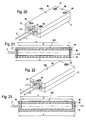
Fig. 16 und dem Lastwiderstand derFig. 17 zusammenge- setzten Alu-Lastwiderstand in 3D-Darstellung mit zwei Fixierelementen und vier Verbindungs- schrauben; - Fig. 21
- einen Längsschnitt aus
Fig. 20 ; - Fig. 22
- den Alu-Lastwiderstand aus
Fig. 20 in 3D- Darstellung mit nur zwei zugleich als Fixier- elemente dienenden Verbindungsschrauben; - Fig. 23
- den Alu-Lastwiderstand der
Fig. 22 in Schnitt- darstellung. - Der in den
Fig. 1 bis 3 dargestellte Alu-Lastwiderstand besteht aus einer Widerstandswendel 1, die auf einem aus Isolierrohstoff bestehenden Wickelkern 2 aufgewickelt ist und mit Anschlussleitern 3 und 4 versehen ist. Der Wickelkern 2 mit der Widerstandswendel 1 befindet sich in koaxialer Lage in einem zylindrischen Metallmantelrohr 5, das an einem Ende mit einem festen Boden 6 und am anderen Ende mit einer Abschlussscheibe 7 versehen ist. Die Abschlussscheibe besteht aus elektrischem Isoliermaterial und sie weist zwei axiale Bohrungen 8 und 9 auf, durch welche die Anschlussleitern 3 und 4 nach außen geführt sind. Die auf dem Wickelkern 2 aufgewickelte Widerstandswendel 1 ist eingebettet in eine hochverdichtete Isolierstoffpackung 10, die aus Quarzsand, aus Magnesiumoxid, aus Siliciumoxid oder dgl. bestehen kann. Aufgabe dieser Isolierstoffpackung 10 ist es, einerseits die Widerstandswendel gegenüber dem Metallmantelrohr 5 elektrisch zu isolieren und andererseits die von der Widerstandswendel erzeugte Wärme mit möglichst geringer zeitlicher Verzögerung an das Metallmantelrohr 5 weiterzuleiten. - Um eine hohe Belastbarkeit des Lastwiderstandes 11 zu gewährleisten, ist das Metallmantelrohr 5 aus Edelstahl hergestellt, der einen relativ kleinen Wärmeausdehnungskoeffizienten besitzt, der insofern von Vorteil ist, als auch im erhitzten Zustand der hohe Verdichtungsgrad der Isolierstoffpackung gewahrt werden kann.
- Zudem besteht auch die Möglichkeit, im Metallmantelrohr 5 statt nur einer Widerstandswendel 1 zwei oder mehrere Widerstandswendeln unterzubringen, und diese bedarfsweise so zu schalten, dass sie den jeweiligen Bedürfnissen am besten entsprechen.
- Der so aufgebaute Lastwiderstand 11 ist in einen, dem Durchmesser des Metallmantelrohrs 5 angepassten zylindrischen Hohlraum 12 eines metallenen, vorzugsweise aus Aluminium oder einer Aluminiumlegierung bestehenden Kühlkörpers 13 so eingesetzt, dass der Lastwiderstand 11 mit seinem Metallmantelrohr mantelflächig in thermischem Kontakt steht mit der Wand 17 des Hohlraums 12. Wie insbesondere aus
Fig. 1 erkennbar ist, weist der Kühlkörper 13 mehrere Luftkammern 14 auf, durch welche eine vergrößerte Oberfläche erzielt wird, über welche die Wärmeabgabe an die Umgebung erfolgt. - Wie aus
Fig. 2 ersichtlich ist, weist der Kühlkörper 13 eine größere axiale mittlere Länge s auf als der Lastwiderstand bzw. dessen Metallmantelrohr 5 mit der Länge s1, was aber nicht unbedingt der Fall sein muss und bei anderen nachfolgend beschriebenen Ausführungsbeispielen der Erfindung auch nicht der Fall ist. - Das Profil des Kühlkörpers 13 mit den Luftkammern 14 wird vorzugsweise im Pressstrangverfahren hergestellt, so dass es von einem langen zusammenhängenden Strang jeweils in passender Länge als Kühlkörper 13 abgeschnitten werden kann. Dass beim Ausführungsbeispiel der
Fig. 1 bis 5 die Enden des Kühlkörpers 13 jeweils schräg abgeschnitten sind, ist mit einer besonderen Anwendung des Ausführungsbeispieles begründet. Selbstverständlich kann der Kühlkörper 13 auch mit planebenen stirnseitigen Enden versehen sein. - Um den Lastwiderstand 11 mit seinem Metallmantelrohr 5 im Kühlkörper 13 so zu befestigen, dass sich das Metallmantelrohr 5 temperaturbedingt axial im Hohlraum 12 bewegen kann, ohne seine vorgegebene Axiallage zu verändern, sind bei allen Ausführungsbeispielen Fixierelemente vorgesehen, die radial in oder durch den Hohlraum 12 und das Querschnittsprofil des Metallmantelrohrs 5 ragen, aber unterschiedlich gestaltet sein können.
- Bei der Ausführungsform der
Fig. 1 bis 3a ist nur ein solches Fixierelement in Form eines radial nach innen gerichteten Vorsprungs 20 vorgesehen, der aus einem radial in die Wand 17 des Hohlraums 12 und somit zugleich in die Deckenwand 17' des Kühlkörpers 13 von oben eingepressten Nocken 20 gebildet ist, der auch vertiefend und somit formschlüssig in das Metallmantelrohr 5 eingetrieben ist und außenseitig ein Sackloch 21 bildet. Im Metallmantelrohr wird dadurch vom Nocken 20 eine angepasste Vertiefung 20' gebildet. - Wie aus
Fig. 3a ersichtlich ist, kann in dem Metallmantelrohr 5 die nockenartige Vertiefung 20' auch mittels einer Schraube 21/1 erzeugt werden, die eine Gewindebohrung 19' der Deckenwand 19 eingeschraubt ist. - Es ist hier zu erwähnen, dass das einzeln angewendete Fixierelement, z.B. als Nocken 20 oder Schraube 21/1 ausgebildet, prinzipiell an jeder Stelle des Metallmantelrohrs 5, insbesondere auch in dessen Längsmitte, angeordnet sein kann.
- Bei der Ausführungsform der
Fig. 4a ist statt des durch einen zylindrischen Stempel erzeugten Nockens bzw. Vorsprungs 20 ein sickenartiger Vorsprung 22 vorgesehen. - Bei der Ausführungsform der
Fig. 4, 5 und 6 sind oberseitig in der Mitte des Kühlkörpers 13 zwei nockenartige Vorsprünge 20 vorgesehen, deren Axialabstand a größer ist als die Länge s1 des Metallmantelrohrs 5. Dabei ist der Abstand a so gewählt, dass sich der Lastwiderstand 11 mit seinem Metallmantelrohr 5 zwischen diesen beiden Nocken 20 temperaturbedingt im Hohlraum 12 in ausreichendem Maße ausdehnen kann, wenn eine entsprechende Erwärmung erfolgt, ohne dabei seine durch die beiden Nocken 20 festgelegte Axiallage zu verändern. - Anstelle der Nocken 20 kann gemäß
Fig. 6a auch jeweils eine Schraube 23 vorgesehen sein, die in die Deckenwand 19 eingeschraubt ist und einen zylindrischen Zapfen 23' als Fixierelement aufweist. - Wie
Fig. 5 sowie dieFig. 6 und 6a zeigen, besteht zwischen den Nocken 20 bzw. den Schrauben 23 und den Stirnseiten des Metallmantelrohres 5 ein axiales Spiel b1 + b2. - Die jeweils außerhalb der Enden des Metallmantelrohrs 5 als Fixierelemente angeordneten Nocken 20 stellen Querschnittsverengungen des Hohlraums 12 dar. Es liegt im Bereich der Variationsmöglichkeiten, die Querschnittsverengungen durch einfaches radiales Eindrücken der Wand 17 des Hohlraums 12 zu realisieren. Dabei kann dieses Eindrücken der Hohlraumwand 17 abschnittweise oder vollumfänglich erfolgen.
- Bei dem Ausführungsbeispiel der
Fig. 7 bis 14 ist der Lastwiderstand 11 mit seinem zylindrischen Metallmantelrohr 5 in einen Kühlkörper 13/1 eingesetzt. Dieser Kühlkörper 13/1 besteht aus einem stranggepressten Hohlkörper mit rechteckigem Querschnittsprofil und zwei Luftkammern 14/1, die symmetrisch zu einem koaxialen, zylindrischen Hohlraum 12/1 angeordnet sind. In diesem Hohlraum 12/1, der von einer zylindrischen Wand 15 gebildet ist, befindet sich der Lastwiderstand 11 mit seinem zylindrischen Metallmantelrohr 5. Dabei ist der Durchmesser des Hohlraums 12/1 wiederum so auf den Außendurchmesser des Metallmantelrohrs 5 abgestimmt, dass eine gute Wärmeübertragung vom Lastwiderstand 11 auf den Kühlkörper 13/1 erfolgen kann. - Während der ebene Boden 16 des Kühlkörpers 13/1 außerhalb der zylindrischen Wand 15 angeordnet ist und eine geschlossene Fläche bildet, weist die Deckenwand 19/1 eine Abstufung 17 mit zwei horizontalen Auflageflächen 18 auf. Dabei ist diese Abstufung 17 so gewählt, dass die beiden Auflageflächen 18 in einer Horizontalebene liegen, welche den im übrigen zylindrischen Hohlraum 12/1 nach Art einer Kreissehne schneidet und dass das Metallmantelrohr 5 diese beiden Auflageflächen 18 nach oben mit einem Teil seines Querschnitts überragt.
- Bei der Ausführungsform der
Fig. 7 ist als Fixierelement eine Querlasche 25 vorgesehen, die mittels zweier Schrauben 26 auf den Auflageflächen 18 befestigt ist und zwar so, dass sie die axiale Lage des Lastwiderstands 11 bzw. des Metallmantelrohrs 5 in axialer Richtung klemmend, d.h. kraftschlüssig fixiert. Zur Anpassung an die Zylinderform des Lastwiderstandes 11 bzw. seines Metallmantelrohres 5, ist die Querlasche 25 unterseitig mit einer kreisbogenförmigen Ausnehmung 27 versehen. - Auch bei dieser Art der Fixierung ist gewährleistet, dass sich das Metallmantelrohr 5 bzw. der gesamte Lastwiderstand 11 in dem Hohlraum 12/1 des Kühlkörpers 13/1 in Längsrichtung temperaturbedingt ausdehnen bzw. verkürzen kann, ohne seine durch die Fixierung vorgegebene Axiallage innerhalb des Kühlkörpers 13/1 zu verändern.
- Bei der Ausführungsform der
Fig. 11 bis 15 ist ein Kühlkörper 13/2 vorgesehen, der sich von dem Kühlkörper 13/1 derFig. 7, 9 und 12 nur dadurch unterscheidet, dass er eine größere Länge s2 aufweist als der Lastwiderstand 11 bzw. dessen Metallmantelrohr 5 mit der Länge s1. Außerdem sind statt der einen Querlasche 25 bei dieser Ausführungsform zwei Querlaschen 25/1 vorgesehen, die jeweils an den Enden des Kühlkörpers 13/2 auf den Auflageflächen 18 in einem Abstand a (Fig. 14 ) so angeordnet sind, dass sie das Metallmantelrohr 5 des Lastwiderstandes 11 mit axialem Spiel b1 + b2 zwischen sich aufnehmen. Somit besteht auch hier die Möglichkeit, dass sich der Lastwiderstand 11 mit seinem Metallmantelrohr 5 zwischen diesen beiden Fixierelementen 25/1 temperaturbedingt axial ausdehnen kann, ohne seine durch die beiden Querlaschen 25/1 vorgegebene Axiallage zu verändern. - In diesem Falle sind die beiden Querlaschen 25/1 etwas schmäler gestaltet als die Querlasche 25. Ihre jeweils einander zugekehrten, als Anschlagflächen für die Enden des Metallmantelrohrs 5 wirkenden Seitenflächen 28 und 28' durchragen dabei segmentartig bzw. sehnenartig den Hohlraum 12/1.
- Bei den in den
Fig. 16 bis 23 dargestellten Ausführungsbeispielen besteht der Kühlkörper 13/3 aus zwei Platten 30 und 31, die auf einer Flachseite ein aus mehreren Längsnuten 32, 33, 34 und 35 sowie einer Kupplungsrippe 36 bestehendes Querschnittsprofil aufweisen. Dabei ist das Profil so ausgebildet, dass beim kongruenten Zusammenfügen dieser beiden Platten 30 und 31 die Kupplungsrippen jeweils in die als Passnut ausgebildete Nut 35 zu liegen kommen. Die beiden übereinstimmenden Nuten 32 bilden einen rechteckigen Hohlraum 37 und die Nuten 33 und 34 jeweils Belüftungskammern 38 und 39. Der Hohlraum 37 dient zur Aufnahme eines im Querschnitt angepassten, rechteckigen Lastwiderstandes 11/1, der analog zum Lastwiderstand 11 aufgebaut ist und mit zwei stirnseitig herausragenden Anschlussleitern 3 und 4 versehen ist. Zur Fixierung des Lastwiderstandes 11/1 ist sein im Querschnitt rechteckiges Metallmantelrohr 5/1 beispielsweise in dem Endabschnitt der beiden Anschlussleiter 3 und 4 oberseitig mit einer runden Vertiefung 40 versehen. Als Fixierelement ist hierbei eine Schraube 43 vorgesehen, von der das untere Ende ihres Schraubenschaftes 41 formschlüssig in diese Vertiefung 40 hineinragt. Die Schraube 43 ist in eine Gewindebohrung 42 der oberen Platte 30 eingeschraubt. Der Schraubenkopf 43 sitzt dabei in einer zylindrischen Ausnehmung 44 der Platte 30. Die Wirkungsweise dieses Fixierelements ist die gleiche wie die des nockenartigen Vorsprungs 20. - Bei entsprechender Formgestaltung der ineinander greifenden Kupplungsrippe 36 und der zugehörigen Aufnahmenut 35 können die beiden Platten 30 und 31 durch Verpressen miteinander verbunden sein. Es besteht aber auch, wie beim Ausführungsbeispiel der
Fig. 20, 22 und 23 , die Möglichkeit, die beiden Platten 30 und 31 durch Schrauben 45 bzw. 49 und 50 zu verbinden. Dabei können die Schrauben 45 jeweils in den Ecken der den Kühlkörper 13/3 bildenden Platten 30 und 31 angeordnet sein, wie inFig. 20 dargestellt, oder so wie beim Ausführungsbeispiel derFig. 22 und 23 , bei dem sie in der Längsmitte angeordnet sind. - In beiden Fällen ist der Kühlkörper 13/3 bzw. sind die beiden den Kühlkörper 13/3 bildenden Platten 30 und 31 jeweils mit einer Länge s versehen, die größer ist als die Länge s1 des Lastwiderstandes 11/1, so dass dieser mit dem erforderlichen axialen Spiel zwischen zwei den Hohlraum 37 in vertikaler Richtung mittig durchragenden Fixierelementen in Form von Spannstiften 47 und 48 oder in Form von Verbindungsschrauben 49 und 50 angeordnet werden kann.
- Während beim Ausführungsbeispiel der
Fig. 20 und 21 die beiden Spannstifte 47 und 48 ausschließlich als Fixierelemente für den dazwischen liegenden Lastwiderstand 11/1 dienen, werden beim Ausführungsbeispiel derFig. 22 und 23 die beiden Verbindungsschrauben 49 und 50 nicht nur als Fixierelemente im oben genannten Sinne verwendet, sondern auch dazu benutzt, die beiden Platten 30 und 31 miteinander zu verbinden. - Auch beim Ausführungsbeispiel der
Fig. 22 und 23 sind die beiden Verbindungsschrauben 49 und 50, die zugleich als Fixierelemente dienen, in einem solchen Abstand a voneinander angeordnet, dass sich der Lastwiderstand 11/1 temperaturbedingt ungehindert dazwischen ausdehnen kann, ohne dabei seine vorbestimmte Axiallage zu verändern.
Claims (12)
- Alu-Lastwiderstand bestehend aus wenigstens einer Widerstandswendel (1), welche mit von außen zugänglichen Anschlussleitern (3, 4) versehenen in einem Metallmantelrohr (5) angeordnet und in einer hoch verdichteten Isolierstoffpackung (10) (MgO, SiO2 oder Quarzsand) eingebettet ist und wobei das Metallmantelrohr (5) in einem sowohl bezüglich seines Querschnitts als auch bezüglich seiner Länge auf die Abmessungen des Metallmantelrohrs (5) abgestimmten Hohlraum (12) eines aus einer Aluminiumlegierung bestehenden Kühlkörpers (13, 13/1, 13/2, 13/3)) angeordnet ist und mit diesem mantelflächig in thermischem Kontakt steht,
dadurch gekennzeichnet,
dass das Metallmantelrohr (5) im Hohlraum (12) des Kühlkörpers (13, 13/1, 13/2, 13/3) mittels wenigstens eines radial in oder durch den Hohlraum (12) und das Querschnittsprofil des Metallmantelrohrs (5) ragenden Fixierelements (20, 23, 25, 25/1, 47, 48, 49, 50) axial derart fixiert ist, dass sich das Metallmantelrohr (5) temperaturbedingt im Hohlraum (12) bewegen kann, ohne seine durch das Fixierelement (20, 23, 25, 25/1, 47, 48, 49, 50) vorgegebene Axiallage zu ändern. - Alu-Lastwiderstand nach Anspruch 1, dadurch gekennzeichnet, dass das Metallmantelrohr (5) aus einem Metall mit kleinem Wärmeausdehnungskoeffizienten, insbesondere aus Edelstahl besteht.
- Alu-Lastwiderstand nach Anspruch 1, dadurch gekennzeichnet, dass das Fixierelement aus einem im Wesentlichen radial nach innen gerichteten Vorsprung (20) besteht.
- Alu-Lastwiderstand nach Anspruch 1, dadurch gekennzeichnet, dass der Vorsprung (20) aus einem radial in die Wand des Hohlraums (12) eingepressten Nocken (20) besteht, der auch vertiefend und somit formschlüssig in das Metallmantelrohr (5) eingetrieben ist.
- Alu-Lastwiderstand nach Anspruch 2, dadurch gekennzeichnet, dass der Vorsprung aus einer in die Wand (19) des Kühlkörpers (13) eingeschraubten Schraube (23) besteht.
- Alu-Lastwiderstand nach Anspruch 1 oder 2, dadurch gekennzeichnet, dass das Metallmantelrohr (5) zwischen zwei nockenartigen, sickenartigen oder rippenartigen Vorsprüngen (20, 22) mit axialem Spiel angeordnet ist.
- Alu-Lastwiderstand nach Anspruch 2, dadurch gekennzeichnet, dass das Metallmantelrohr (5) des Lastwiderstands (11) zwischen zwei radial in den Hohlraum (12) des Kühlkörpers (13) hineinragenden Schrauben (23) mit axialem Spiel (b1 + b2) angeordnet ist.
- Alu-Lastwiderstand nach Anspruch 1, dadurch gekennzeichnet, dass das Fixierelement aus einem radialen Druckstück (25) besteht, das mittels einer oder mehrerer Schrauben (26) kraftschlüssig fixierend auf dem Metallmantelrohr (5) des Lastwiderstands (11) aufliegt.
- Alu-Lastwiderstand nach Anspruch 1, dadurch gekennzeichnet, dass als Fixierelemente zwei das Metallmantelrohr (5) des Lastwiderstands (11) im Hohlraum (12) des Kühlkörpers (13/2) zwischen sich aufnehmende Querlaschen (25/1) dienen, die in einem axialen Abstand (a) voneinander am Kühlkörper (13/2) angeordnet sind, der um wenigstens das temperaturbedingte Ausdehnungsmaß des Metallmantelrohrs (5) größer ist als dessen Länge (s1).
- Alu-Lastwiderstand nach Anspruch 1, dadurch gekennzeichnet, dass als Fixierelemente zwei das Metallmantelrohr (5) des Lastwiderstands (11) im Hohlraum (12) des Kühlkörpers (13/3) mit axialem Spiel (b1 + b2) zwischen sich aufnehmende Querstifte (47, 48) vorgesehen sind, die den Hohlraum (12) diametral oder sehnenartig verlaufend durchragen und in jeweils koaxialen Bohrungen der Hohlraumwand (17) befestigt sind.
- Alu-Lastwiderstand nach Anspruch 1 mit einem aus zwei Gehäuseteilen (30, 31) bestehenden Kühlkörper, dadurch gekennzeichnet, dass die beiden Gehäuseteile (30, 31) unter Einschluss des Lastwiderstands (11) durch Schrauben (49, 50) miteinander verbunden sind, welche den Hohlraum (12), in dem sich der Lastwiderstand (11) befindet, in einem axialen Abstand (a) voneinander durchragen, der um wenigstens das temperaturbedingte Ausdehnungsmaß des Metallmantelrohrs größer ist als dessen Länge (s1).
- Alu-Lastwiderstand nach Anspruch 1, dadurch gekennzeichnet, dass das Metallmantelrohr (5) zwischen zwei Querschnittsverengungen der Wand (17) des Hohlraums (12) mit axialem Spiel angeordnet ist.
Applications Claiming Priority (1)
| Application Number | Priority Date | Filing Date | Title |
|---|---|---|---|
| DE202008014586U DE202008014586U1 (de) | 2008-11-03 | 2008-11-03 | Aluminium-Lastwiderstand |
Publications (3)
| Publication Number | Publication Date |
|---|---|
| EP2182529A2 true EP2182529A2 (de) | 2010-05-05 |
| EP2182529A3 EP2182529A3 (de) | 2010-07-28 |
| EP2182529B1 EP2182529B1 (de) | 2011-04-13 |
Family
ID=40299483
Family Applications (2)
| Application Number | Title | Priority Date | Filing Date |
|---|---|---|---|
| EP09013450A Active EP2182529B1 (de) | 2008-11-03 | 2009-10-24 | Aluminium-Lastwiderstand |
| EP09013457A Active EP2182528B1 (de) | 2008-11-03 | 2009-10-26 | Vorrichtung zum Befestigen eines Lastwiderstandes |
Family Applications After (1)
| Application Number | Title | Priority Date | Filing Date |
|---|---|---|---|
| EP09013457A Active EP2182528B1 (de) | 2008-11-03 | 2009-10-26 | Vorrichtung zum Befestigen eines Lastwiderstandes |
Country Status (4)
| Country | Link |
|---|---|
| EP (2) | EP2182529B1 (de) |
| AT (2) | ATE505800T1 (de) |
| DE (4) | DE202008014586U1 (de) |
| DK (2) | DK2182529T3 (de) |
Cited By (2)
| Publication number | Priority date | Publication date | Assignee | Title |
|---|---|---|---|---|
| CN103280283A (zh) * | 2013-04-24 | 2013-09-04 | 上海德程汇斯电气有限公司 | 一种耐高温制动电阻 |
| JP2014157891A (ja) * | 2013-02-15 | 2014-08-28 | Tamura Thermal Device Corp | ヒートシンク付抵抗器 |
Families Citing this family (8)
| Publication number | Priority date | Publication date | Assignee | Title |
|---|---|---|---|---|
| US7751370B2 (en) | 2001-07-13 | 2010-07-06 | Qualcomm Incorporated | Method and apparatus for forward link rate scheduling |
| DE102011001362A1 (de) * | 2010-08-11 | 2012-02-16 | Dbk David + Baader Gmbh | Bremswiderstand |
| DE102015213405A1 (de) * | 2015-07-16 | 2017-01-19 | Conti Temic Microelectronic Gmbh | Schaltungskomponententräger-Anordnung, Verfahren zu dessen Herstellung und Kombination mit einem Montagekörper |
| EP3401617A1 (de) * | 2017-05-12 | 2018-11-14 | Mahle International GmbH | Elektrische heizeinrichtung |
| DE102017113600A1 (de) | 2017-06-20 | 2018-12-20 | Vishay Electronic Gmbh | Leistungswiderstand |
| DE202018102531U1 (de) * | 2018-05-07 | 2018-05-22 | Türk & Hillinger GmbH | Heizpatrone mit Regelelement |
| TWD200403S (zh) | 2018-08-20 | 2019-10-21 | 德商斯泰格控股有限公司 | 換流器(二) |
| DE102018124985B4 (de) | 2018-10-10 | 2022-05-05 | Stego-Holding Gmbh | Temperiervorrichtung und System |
Citations (1)
| Publication number | Priority date | Publication date | Assignee | Title |
|---|---|---|---|---|
| DE202007014360U1 (de) | 2007-10-12 | 2009-02-26 | Türk & Hillinger GmbH | Aluminium-Heizwiderstand |
Family Cites Families (5)
| Publication number | Priority date | Publication date | Assignee | Title |
|---|---|---|---|---|
| GB1058537A (en) * | 1965-07-20 | 1967-02-15 | Dale Electronics | Improvements in or relating to electrical resistors |
| DE9405513U1 (de) * | 1994-03-31 | 1994-07-21 | Türk & Hillinger GmbH, 78532 Tuttlingen | Elektrischer Heizkörper mit Kühlelementen |
| JPH0831602A (ja) * | 1994-07-12 | 1996-02-02 | Tokai Konetsu Kogyo Co Ltd | 間接冷却式抵抗器 |
| JP2001185407A (ja) * | 1999-12-24 | 2001-07-06 | Seiden Techno Co Ltd | 電力用抵抗器とその抵抗素子及びそれらの製造方法 |
| US7012226B1 (en) * | 2004-06-02 | 2006-03-14 | Durex International Corporation | Cartridge heater with a release coating |
-
2008
- 2008-11-03 DE DE202008014586U patent/DE202008014586U1/de not_active Expired - Lifetime
-
2009
- 2009-03-26 DE DE202009004058U patent/DE202009004058U1/de not_active Expired - Lifetime
- 2009-10-24 EP EP09013450A patent/EP2182529B1/de active Active
- 2009-10-24 AT AT09013450T patent/ATE505800T1/de active
- 2009-10-24 DK DK09013450.3T patent/DK2182529T3/da active
- 2009-10-24 DE DE502009000539T patent/DE502009000539D1/de active Active
- 2009-10-26 DE DE502009000500T patent/DE502009000500D1/de active Active
- 2009-10-26 DK DK09013457.8T patent/DK2182528T3/da active
- 2009-10-26 AT AT09013457T patent/ATE504068T1/de active
- 2009-10-26 EP EP09013457A patent/EP2182528B1/de active Active
Patent Citations (1)
| Publication number | Priority date | Publication date | Assignee | Title |
|---|---|---|---|---|
| DE202007014360U1 (de) | 2007-10-12 | 2009-02-26 | Türk & Hillinger GmbH | Aluminium-Heizwiderstand |
Cited By (2)
| Publication number | Priority date | Publication date | Assignee | Title |
|---|---|---|---|---|
| JP2014157891A (ja) * | 2013-02-15 | 2014-08-28 | Tamura Thermal Device Corp | ヒートシンク付抵抗器 |
| CN103280283A (zh) * | 2013-04-24 | 2013-09-04 | 上海德程汇斯电气有限公司 | 一种耐高温制动电阻 |
Also Published As
| Publication number | Publication date |
|---|---|
| DE202009004058U1 (de) | 2009-06-04 |
| DE202008014586U1 (de) | 2009-01-29 |
| EP2182529B1 (de) | 2011-04-13 |
| EP2182528A2 (de) | 2010-05-05 |
| ATE505800T1 (de) | 2011-04-15 |
| DE502009000500D1 (de) | 2011-05-12 |
| EP2182529A3 (de) | 2010-07-28 |
| ATE504068T1 (de) | 2011-04-15 |
| EP2182528B1 (de) | 2011-03-30 |
| EP2182528A3 (de) | 2010-07-28 |
| DK2182529T3 (da) | 2011-07-18 |
| DE502009000539D1 (de) | 2011-05-26 |
| DK2182528T3 (da) | 2011-07-18 |
Similar Documents
| Publication | Publication Date | Title |
|---|---|---|
| EP2182529B1 (de) | Aluminium-Lastwiderstand | |
| DE2314168C3 (de) | Einstückiges Ankerelement für Stehbolzen | |
| EP0642141A1 (de) | Überspannungsableiter | |
| DE102009040809A1 (de) | Elektrische Heizvorrichtung und Verfahren zur Herstellung einer elektrischen Heizvorrichtung | |
| EP0545038A1 (de) | Überspannungsableiter | |
| DE4006028A1 (de) | Verbindungsbolzen und anordnung aus komponenten | |
| DE19726496B4 (de) | Anlasser für eine Brennkraftmaschine | |
| DE3144901C2 (de) | Elektrisch isolierte Verbindung zwischen zwei gleichachsig angeordneten, stabförmigen Elementen aus Metall insbesondere Schraubendreher | |
| DE102009043526A1 (de) | Vorrichtung zur elektrischen Energiespeicherung | |
| EP0425981A2 (de) | Heisskanalblock | |
| DE3008287A1 (de) | Bolzen fuer schubstangen | |
| EP3047159B1 (de) | Profilverbinder sowie profilverbund | |
| DE1933627A1 (de) | Verfahren zur Herstellung einer Verbindung einer Elektrodenspitze mit einer Elektrode | |
| DE19931306C2 (de) | Verfahren zur Herstellung von leichten keramischen Bauteilen sowie Bausatz zur Erstellung eines solchen leichten keramischen Bauteils | |
| EP1948945B1 (de) | Montageschraube zur befestigung von beschlagteilen, insbesondere von bandteilen an hohlkammerprofilen | |
| DE1159075B (de) | Elektrischer Schaltapparat mit ausgepraegter Achse | |
| DE102004039300A1 (de) | Befestigungselement | |
| DE102009017806A1 (de) | Befestigungselement | |
| EP0927621B1 (de) | Heisskanalabschnitt, insbesondere Heisskanaldüse für eine Spritzgiessmaschine oder Kunststoffspritzgiessform | |
| DE102009056003B4 (de) | Elektrischer Widerstand | |
| DE19737995A1 (de) | Bauelement | |
| DE20016611U1 (de) | Tür- und/oder Fensterprofil | |
| DE19952719A1 (de) | Isolator für eine Hochspannungsschaltanlage | |
| EP0340700B1 (de) | Gehäuse für Reihenschaltgerät | |
| DE3701809C2 (de) |
Legal Events
| Date | Code | Title | Description |
|---|---|---|---|
| PUAI | Public reference made under article 153(3) epc to a published international application that has entered the european phase |
Free format text: ORIGINAL CODE: 0009012 |
|
| AK | Designated contracting states |
Kind code of ref document: A2 Designated state(s): AT BE BG CH CY CZ DE DK EE ES FI FR GB GR HR HU IE IS IT LI LT LU LV MC MK MT NL NO PL PT RO SE SI SK SM TR |
|
| AX | Request for extension of the european patent |
Extension state: AL BA RS |
|
| PUAL | Search report despatched |
Free format text: ORIGINAL CODE: 0009013 |
|
| AK | Designated contracting states |
Kind code of ref document: A3 Designated state(s): AT BE BG CH CY CZ DE DK EE ES FI FR GB GR HR HU IE IS IT LI LT LU LV MC MK MT NL NO PL PT RO SE SI SK SM TR |
|
| AX | Request for extension of the european patent |
Extension state: AL BA RS |
|
| RIC1 | Information provided on ipc code assigned before grant |
Ipc: H05B 3/44 20060101ALI20100618BHEP Ipc: H01C 17/22 20060101ALI20100618BHEP Ipc: H01C 1/08 20060101ALI20100618BHEP Ipc: H01C 1/084 20060101ALI20100618BHEP Ipc: H01C 3/20 20060101ALI20100618BHEP Ipc: H01C 1/036 20060101AFI20100303BHEP |
|
| GRAP | Despatch of communication of intention to grant a patent |
Free format text: ORIGINAL CODE: EPIDOSNIGR1 |
|
| 17P | Request for examination filed |
Effective date: 20101109 |
|
| GRAS | Grant fee paid |
Free format text: ORIGINAL CODE: EPIDOSNIGR3 |
|
| GRAA | (expected) grant |
Free format text: ORIGINAL CODE: 0009210 |
|
| AK | Designated contracting states |
Kind code of ref document: B1 Designated state(s): AT BE BG CH CY CZ DE DK EE ES FI FR GB GR HR HU IE IS IT LI LT LU LV MC MK MT NL NO PL PT RO SE SI SK SM TR |
|
| REG | Reference to a national code |
Ref country code: GB Ref legal event code: FG4D Free format text: NOT ENGLISH |
|
| REG | Reference to a national code |
Ref country code: CH Ref legal event code: EP |
|
| REG | Reference to a national code |
Ref country code: IE Ref legal event code: FG4D Free format text: LANGUAGE OF EP DOCUMENT: GERMAN |
|
| REF | Corresponds to: |
Ref document number: 502009000539 Country of ref document: DE Date of ref document: 20110526 Kind code of ref document: P |
|
| REG | Reference to a national code |
Ref country code: DE Ref legal event code: R096 Ref document number: 502009000539 Country of ref document: DE Effective date: 20110526 |
|
| REG | Reference to a national code |
Ref country code: DK Ref legal event code: T3 |
|
| REG | Reference to a national code |
Ref country code: NL Ref legal event code: VDEP Effective date: 20110413 |
|
| LTIE | Lt: invalidation of european patent or patent extension |
Effective date: 20110413 |
|
| PG25 | Lapsed in a contracting state [announced via postgrant information from national office to epo] |
Ref country code: HR Free format text: LAPSE BECAUSE OF FAILURE TO SUBMIT A TRANSLATION OF THE DESCRIPTION OR TO PAY THE FEE WITHIN THE PRESCRIBED TIME-LIMIT Effective date: 20110413 Ref country code: NO Free format text: LAPSE BECAUSE OF FAILURE TO SUBMIT A TRANSLATION OF THE DESCRIPTION OR TO PAY THE FEE WITHIN THE PRESCRIBED TIME-LIMIT Effective date: 20110713 Ref country code: PT Free format text: LAPSE BECAUSE OF FAILURE TO SUBMIT A TRANSLATION OF THE DESCRIPTION OR TO PAY THE FEE WITHIN THE PRESCRIBED TIME-LIMIT Effective date: 20110816 Ref country code: LT Free format text: LAPSE BECAUSE OF FAILURE TO SUBMIT A TRANSLATION OF THE DESCRIPTION OR TO PAY THE FEE WITHIN THE PRESCRIBED TIME-LIMIT Effective date: 20110413 Ref country code: SE Free format text: LAPSE BECAUSE OF FAILURE TO SUBMIT A TRANSLATION OF THE DESCRIPTION OR TO PAY THE FEE WITHIN THE PRESCRIBED TIME-LIMIT Effective date: 20110413 |
|
| REG | Reference to a national code |
Ref country code: IE Ref legal event code: FD4D |
|
| PG25 | Lapsed in a contracting state [announced via postgrant information from national office to epo] |
Ref country code: IS Free format text: LAPSE BECAUSE OF FAILURE TO SUBMIT A TRANSLATION OF THE DESCRIPTION OR TO PAY THE FEE WITHIN THE PRESCRIBED TIME-LIMIT Effective date: 20110813 Ref country code: SI Free format text: LAPSE BECAUSE OF FAILURE TO SUBMIT A TRANSLATION OF THE DESCRIPTION OR TO PAY THE FEE WITHIN THE PRESCRIBED TIME-LIMIT Effective date: 20110413 Ref country code: GR Free format text: LAPSE BECAUSE OF FAILURE TO SUBMIT A TRANSLATION OF THE DESCRIPTION OR TO PAY THE FEE WITHIN THE PRESCRIBED TIME-LIMIT Effective date: 20110714 Ref country code: CY Free format text: LAPSE BECAUSE OF FAILURE TO SUBMIT A TRANSLATION OF THE DESCRIPTION OR TO PAY THE FEE WITHIN THE PRESCRIBED TIME-LIMIT Effective date: 20110413 Ref country code: ES Free format text: LAPSE BECAUSE OF FAILURE TO SUBMIT A TRANSLATION OF THE DESCRIPTION OR TO PAY THE FEE WITHIN THE PRESCRIBED TIME-LIMIT Effective date: 20110724 Ref country code: LV Free format text: LAPSE BECAUSE OF FAILURE TO SUBMIT A TRANSLATION OF THE DESCRIPTION OR TO PAY THE FEE WITHIN THE PRESCRIBED TIME-LIMIT Effective date: 20110413 Ref country code: FI Free format text: LAPSE BECAUSE OF FAILURE TO SUBMIT A TRANSLATION OF THE DESCRIPTION OR TO PAY THE FEE WITHIN THE PRESCRIBED TIME-LIMIT Effective date: 20110413 |
|
| PG25 | Lapsed in a contracting state [announced via postgrant information from national office to epo] |
Ref country code: NL Free format text: LAPSE BECAUSE OF FAILURE TO SUBMIT A TRANSLATION OF THE DESCRIPTION OR TO PAY THE FEE WITHIN THE PRESCRIBED TIME-LIMIT Effective date: 20110413 |
|
| PG25 | Lapsed in a contracting state [announced via postgrant information from national office to epo] |
Ref country code: EE Free format text: LAPSE BECAUSE OF FAILURE TO SUBMIT A TRANSLATION OF THE DESCRIPTION OR TO PAY THE FEE WITHIN THE PRESCRIBED TIME-LIMIT Effective date: 20110413 Ref country code: IE Free format text: LAPSE BECAUSE OF FAILURE TO SUBMIT A TRANSLATION OF THE DESCRIPTION OR TO PAY THE FEE WITHIN THE PRESCRIBED TIME-LIMIT Effective date: 20110413 Ref country code: CZ Free format text: LAPSE BECAUSE OF FAILURE TO SUBMIT A TRANSLATION OF THE DESCRIPTION OR TO PAY THE FEE WITHIN THE PRESCRIBED TIME-LIMIT Effective date: 20110413 |
|
| PLBE | No opposition filed within time limit |
Free format text: ORIGINAL CODE: 0009261 |
|
| STAA | Information on the status of an ep patent application or granted ep patent |
Free format text: STATUS: NO OPPOSITION FILED WITHIN TIME LIMIT |
|
| PG25 | Lapsed in a contracting state [announced via postgrant information from national office to epo] |
Ref country code: RO Free format text: LAPSE BECAUSE OF FAILURE TO SUBMIT A TRANSLATION OF THE DESCRIPTION OR TO PAY THE FEE WITHIN THE PRESCRIBED TIME-LIMIT Effective date: 20110413 Ref country code: PL Free format text: LAPSE BECAUSE OF FAILURE TO SUBMIT A TRANSLATION OF THE DESCRIPTION OR TO PAY THE FEE WITHIN THE PRESCRIBED TIME-LIMIT Effective date: 20110413 Ref country code: SK Free format text: LAPSE BECAUSE OF FAILURE TO SUBMIT A TRANSLATION OF THE DESCRIPTION OR TO PAY THE FEE WITHIN THE PRESCRIBED TIME-LIMIT Effective date: 20110413 |
|
| 26N | No opposition filed |
Effective date: 20120116 |
|
| BERE | Be: lapsed |
Owner name: TURK + HILLINGER G.M.B.H. Effective date: 20111031 |
|
| REG | Reference to a national code |
Ref country code: DE Ref legal event code: R097 Ref document number: 502009000539 Country of ref document: DE Effective date: 20120116 |
|
| PG25 | Lapsed in a contracting state [announced via postgrant information from national office to epo] |
Ref country code: IT Free format text: LAPSE BECAUSE OF FAILURE TO SUBMIT A TRANSLATION OF THE DESCRIPTION OR TO PAY THE FEE WITHIN THE PRESCRIBED TIME-LIMIT Effective date: 20110413 Ref country code: MC Free format text: LAPSE BECAUSE OF NON-PAYMENT OF DUE FEES Effective date: 20111031 |
|
| REG | Reference to a national code |
Ref country code: FR Ref legal event code: ST Effective date: 20120629 |
|
| PG25 | Lapsed in a contracting state [announced via postgrant information from national office to epo] |
Ref country code: BE Free format text: LAPSE BECAUSE OF NON-PAYMENT OF DUE FEES Effective date: 20111031 |
|
| PG25 | Lapsed in a contracting state [announced via postgrant information from national office to epo] |
Ref country code: FR Free format text: LAPSE BECAUSE OF NON-PAYMENT OF DUE FEES Effective date: 20111102 |
|
| PG25 | Lapsed in a contracting state [announced via postgrant information from national office to epo] |
Ref country code: MT Free format text: LAPSE BECAUSE OF FAILURE TO SUBMIT A TRANSLATION OF THE DESCRIPTION OR TO PAY THE FEE WITHIN THE PRESCRIBED TIME-LIMIT Effective date: 20110413 Ref country code: MK Free format text: LAPSE BECAUSE OF FAILURE TO SUBMIT A TRANSLATION OF THE DESCRIPTION OR TO PAY THE FEE WITHIN THE PRESCRIBED TIME-LIMIT Effective date: 20110413 |
|
| PG25 | Lapsed in a contracting state [announced via postgrant information from national office to epo] |
Ref country code: SM Free format text: LAPSE BECAUSE OF FAILURE TO SUBMIT A TRANSLATION OF THE DESCRIPTION OR TO PAY THE FEE WITHIN THE PRESCRIBED TIME-LIMIT Effective date: 20110413 |
|
| PG25 | Lapsed in a contracting state [announced via postgrant information from national office to epo] |
Ref country code: LU Free format text: LAPSE BECAUSE OF NON-PAYMENT OF DUE FEES Effective date: 20111024 |
|
| PG25 | Lapsed in a contracting state [announced via postgrant information from national office to epo] |
Ref country code: BG Free format text: LAPSE BECAUSE OF FAILURE TO SUBMIT A TRANSLATION OF THE DESCRIPTION OR TO PAY THE FEE WITHIN THE PRESCRIBED TIME-LIMIT Effective date: 20110713 |
|
| PG25 | Lapsed in a contracting state [announced via postgrant information from national office to epo] |
Ref country code: TR Free format text: LAPSE BECAUSE OF FAILURE TO SUBMIT A TRANSLATION OF THE DESCRIPTION OR TO PAY THE FEE WITHIN THE PRESCRIBED TIME-LIMIT Effective date: 20110413 |
|
| PG25 | Lapsed in a contracting state [announced via postgrant information from national office to epo] |
Ref country code: HU Free format text: LAPSE BECAUSE OF FAILURE TO SUBMIT A TRANSLATION OF THE DESCRIPTION OR TO PAY THE FEE WITHIN THE PRESCRIBED TIME-LIMIT Effective date: 20110413 |
|
| REG | Reference to a national code |
Ref country code: CH Ref legal event code: PL |
|
| GBPC | Gb: european patent ceased through non-payment of renewal fee |
Effective date: 20131024 |
|
| PG25 | Lapsed in a contracting state [announced via postgrant information from national office to epo] |
Ref country code: CH Free format text: LAPSE BECAUSE OF NON-PAYMENT OF DUE FEES Effective date: 20131031 Ref country code: LI Free format text: LAPSE BECAUSE OF NON-PAYMENT OF DUE FEES Effective date: 20131031 Ref country code: GB Free format text: LAPSE BECAUSE OF NON-PAYMENT OF DUE FEES Effective date: 20131024 |
|
| REG | Reference to a national code |
Ref country code: AT Ref legal event code: MM01 Ref document number: 505800 Country of ref document: AT Kind code of ref document: T Effective date: 20141024 |
|
| PG25 | Lapsed in a contracting state [announced via postgrant information from national office to epo] |
Ref country code: AT Free format text: LAPSE BECAUSE OF NON-PAYMENT OF DUE FEES Effective date: 20141024 |
|
| PGFP | Annual fee paid to national office [announced via postgrant information from national office to epo] |
Ref country code: DE Payment date: 20251125 Year of fee payment: 17 |
|
| PGFP | Annual fee paid to national office [announced via postgrant information from national office to epo] |
Ref country code: DK Payment date: 20251023 Year of fee payment: 17 |