EP2182529A2 - Résistance de charge en aluminium - Google Patents
Résistance de charge en aluminium Download PDFInfo
- Publication number
- EP2182529A2 EP2182529A2 EP09013450A EP09013450A EP2182529A2 EP 2182529 A2 EP2182529 A2 EP 2182529A2 EP 09013450 A EP09013450 A EP 09013450A EP 09013450 A EP09013450 A EP 09013450A EP 2182529 A2 EP2182529 A2 EP 2182529A2
- Authority
- EP
- European Patent Office
- Prior art keywords
- load resistor
- cavity
- metal casing
- heat sink
- aluminum
- Prior art date
- Legal status (The legal status is an assumption and is not a legal conclusion. Google has not performed a legal analysis and makes no representation as to the accuracy of the status listed.)
- Granted
Links
Images


Classifications
-
- H—ELECTRICITY
- H01—ELECTRIC ELEMENTS
- H01C—RESISTORS
- H01C3/00—Non-adjustable metal resistors made of wire or ribbon, e.g. coiled, woven or formed as grids
- H01C3/14—Non-adjustable metal resistors made of wire or ribbon, e.g. coiled, woven or formed as grids the resistive element being formed in two or more coils or loops continuously wound as a spiral, helical or toroidal winding
- H01C3/20—Non-adjustable metal resistors made of wire or ribbon, e.g. coiled, woven or formed as grids the resistive element being formed in two or more coils or loops continuously wound as a spiral, helical or toroidal winding wound on cylindrical or prismatic base
-
- H—ELECTRICITY
- H01—ELECTRIC ELEMENTS
- H01C—RESISTORS
- H01C1/00—Details
- H01C1/01—Mounting; Supporting
-
- H—ELECTRICITY
- H01—ELECTRIC ELEMENTS
- H01C—RESISTORS
- H01C1/00—Details
- H01C1/02—Housing; Enclosing; Embedding; Filling the housing or enclosure
-
- H—ELECTRICITY
- H01—ELECTRIC ELEMENTS
- H01C—RESISTORS
- H01C1/00—Details
- H01C1/02—Housing; Enclosing; Embedding; Filling the housing or enclosure
- H01C1/034—Housing; Enclosing; Embedding; Filling the housing or enclosure the housing or enclosure being formed as coating or mould without outer sheath
- H01C1/036—Housing; Enclosing; Embedding; Filling the housing or enclosure the housing or enclosure being formed as coating or mould without outer sheath on wound resistive element
-
- H—ELECTRICITY
- H01—ELECTRIC ELEMENTS
- H01C—RESISTORS
- H01C1/00—Details
- H01C1/08—Cooling, heating or ventilating arrangements
-
- H—ELECTRICITY
- H01—ELECTRIC ELEMENTS
- H01C—RESISTORS
- H01C1/00—Details
- H01C1/08—Cooling, heating or ventilating arrangements
- H01C1/084—Cooling, heating or ventilating arrangements using self-cooling, e.g. fins, heat sinks
-
- H—ELECTRICITY
- H01—ELECTRIC ELEMENTS
- H01C—RESISTORS
- H01C17/00—Apparatus or processes specially adapted for manufacturing resistors
- H01C17/22—Apparatus or processes specially adapted for manufacturing resistors adapted for trimming
-
- H—ELECTRICITY
- H05—ELECTRIC TECHNIQUES NOT OTHERWISE PROVIDED FOR
- H05B—ELECTRIC HEATING; ELECTRIC LIGHT SOURCES NOT OTHERWISE PROVIDED FOR; CIRCUIT ARRANGEMENTS FOR ELECTRIC LIGHT SOURCES, IN GENERAL
- H05B3/00—Ohmic-resistance heating
- H05B3/40—Heating elements having the shape of rods or tubes
- H05B3/42—Heating elements having the shape of rods or tubes non-flexible
- H05B3/44—Heating elements having the shape of rods or tubes non-flexible heating conductor arranged within rods or tubes of insulating material
Definitions
- the invention relates to an aluminum load resistor consisting of at least one resistance coil, which is provided with externally accessible connection wires arranged in a metal casing tube and embedded in a highly encapsulated in the metal casing insulating material and wherein the metal casing tube in a both with respect to its cross-section as well as with respect to its length
- the dimensions of the metal casing tube matched cavity of an existing aluminum alloy heat sink is arranged and is in contact with this jacket surface in thermal contact.
- Aluminum load resistors are known. They are used to destroy surplus electrical energy temporarily generated during idle or overrun operation of machines by transforming them into heat and deliver them to the environment in a suitable way. In this case, very high peak loads can occur for a short time, which can lead to high mechanical stresses of the material. For cost reasons, small, compact designs are generally desired. However, these require a high mechanical strength and resilience of the components. A leading to this goal way is the granulated, z. As consisting of MgO, SiO 2 or quartz sand insulating material in which the resistance coil is embedded high to compress and keep it free of smallest voids or cracks. Another prerequisite is the high strength of the metal shell, which must withstand the thermal expansion forces of the compacted Isolierstoffmasse.
- Such aluminum load resistors may also contain a plurality of interconnected or separately switchable resistance coils.
- the heat sink is provided with a through hole in which the load resistance is pressed tightly with such a metal casing pipe.
- the heat sink is formed in several parts from at least two housing parts which are pressed or screwed together for fixed recording of the load resistance with its metal casing pipe.
- the metal casing tube may have any cross-sectional shape, in particular, this may be formed annular or rectangular.
- the invention has for its object to provide a heavy duty aluminum load resistor of the type mentioned, in which the axial displacement of the metal casing tube in the heat sink in a simple manner, i. by simple means, is prevented.
- the metal casing tube is fixed axially in the cavity of the heat sink by means of at least one radially projecting into or through the cavity and the cross-sectional profile of the metal casing tube fixing that the metal casing tube can move due to temperature in the cavity, without its by the fixing to change the specified axial position.
- the particular advantage of this solution according to the invention is that the metal sheath tube of the load resistance in the axial direction of the location of the fixing element in the cavity of the heat sink can expand and shorten, while still always in the same place remains. It is immaterial whether the fixing element is arranged in an end region of the metal casing tube or in the middle and is positively or non-positively clamped with the metal shell in engagement. The temperature-related linear expansion can take place from the location of the projection in both axial directions.
- the fixing element or the fixing elements may consist of a substantially radially inwardly directed projection, which may be formed differently.
- this projection can for example consist of a radially pressed into the wall of the cavity cams or from a pressed-in the wall of the cavity bead or which is also deepened and thus positively driven into the metal casing pipe.
- the metal casing pipe or the heating cartridge according to claim 5 between two cam-like, bead-like projections with axial play or according to claim 6 between two radially projecting into the cavity of the heat sink screws, so that the metal casing pipe or .
- the heating cartridge can expand due to the predetermined axial clearance in the axial direction due to temperature, without changing its predetermined position.
- the in the Fig. 1 to 3 illustrated aluminum load resistor consists of a resistance coil 1, which is wound on a winding core 2 consisting of insulating raw material and is provided with connecting conductors 3 and 4.
- the winding core 2 with the resistance coil 1 is in a coaxial position in a cylindrical metal casing tube 5, which is provided at one end with a fixed base 6 and at the other end with a cover plate 7.
- the cover plate consists of electrical insulating material and it has two axial bores 8 and 9, through which the connection conductors 3 and 4 are led to the outside.
- the wound on the winding core 2 resistance coil 1 is embedded in a high density Isolierstoffpackung 10, which may consist of quartz sand, magnesium oxide, silica or the like.
- the object of this insulating material 10 is, on the one hand electrically to isolate the resistance coil relative to the metal jacket tube 5 and on the other hand forward the heat generated by the resistance coil with the least possible time delay to the metal jacket tube 5.
- the metal casing pipe 5 is made of stainless steel made, which has a relatively small coefficient of thermal expansion, which is advantageous in that as well as in the heated state, the high degree of compression of the insulating material package can be maintained.
- the thus constructed load resistor 11 is inserted into a, the diameter of the metal casing tube 5 adapted cylindrical cavity 12 of a metal, preferably made of aluminum or an aluminum alloy heat sink 13 so that the load resistor 11 with its metal jacket tube mantelflächig in thermal contact with the wall 17 of the Cavity 12.
- the heat sink 13 a plurality of air chambers 14, through which an enlarged surface is achieved, via which the heat is dissipated to the environment.
- the heat sink 13 has a greater axial axial length s than the load resistance or its metal jacket tube 5 with the length s1, but this is not necessarily the case and in other embodiments of the invention described below is not the case.
- the profile of the heat sink 13 with the air chambers 14 is preferably made in the compression molding process, so that it can be cut off from a long contiguous strand in each case in a suitable length as the heat sink 13. That in the embodiment of the Fig. 1 to 5 the ends of the heat sink 13 are each cut obliquely, is justified by a particular application of the embodiment.
- the heat sink 13 may also be provided with plane front ends.
- Fixing elements are provided in all embodiments, which project radially into or through the cavity 12 and the cross-sectional profile of the metal casing tube 5, but can be designed differently.
- a fixing element in the form of a radially inwardly directed projection 20 is provided, which is formed from a radially in the wall 17 of the cavity 12 and thus at the same time in the top wall 17 'of the heat sink 13 from above pressed cam 20, which also deepening and thus positively driven into the metal casing tube 5 and the outside forms a blind hole 21.
- the cam 20 In the metal casing pipe is thereby formed by the cam 20 a matching recess 20 '.
- the individually applied fixing element for example formed as a cam 20 or screw 21/1, in principle at each point of the metal casing pipe 5, in particular in the longitudinal center, may be arranged.
- a bead-like projection 22 is provided.
- 5 and 6 are the upper side in the middle of the heat sink 13 are two cam-like projections 20 is provided whose axial distance a is larger than the length s1 of the metal jacket tube 5.
- the distance a is selected so that the load resistor 11 due to the temperature, with its metal casing 5 between these two cams 20 in the cavity 12 can expand sufficiently, if a corresponding heating takes place, without changing its fixed by the two cams 20 axial position.
- each one screw 23 may be provided which is screwed into the top wall 19 and has a cylindrical pin 23 'as a fixing element.
- the cams 20 which are each arranged outside the ends of the metal jacket tube 5 as fixing elements represent cross-sectional constrictions of the cavity 12. It is within the range of possible variations to realize the cross-sectional constrictions by simply radial impressions of the wall 17 of the cavity 12. This impressions of the cavity wall 17 can be made in sections or in full.
- the load resistor 11 is inserted with its cylindrical metal casing tube 5 in a heat sink 13/1.
- This heat sink 13/1 consists of an extruded hollow body with a rectangular cross-sectional profile and two air chambers 14/1, which are arranged symmetrically to a coaxial, cylindrical cavity 12/1.
- this cavity 12/1 which is formed by a cylindrical wall 15, there is the load resistor 11 with its cylindrical metal casing tube 5.
- the diameter of the cavity 12/1 in turn so on the outer diameter of the metal casing tube 5 tuned that a good heat transfer from the load resistor 11 can be made to the heat sink 13/1.
- the top wall 19/1 has a step 17 with two horizontal bearing surfaces 18.
- this gradation 17 is chosen so that the two bearing surfaces 18 lie in a horizontal plane which intersects the otherwise cylindrical cavity 12/1 in the manner of a chord and that the metal casing tube 5 projects beyond these two bearing surfaces 18 upwards with a portion of its cross section.
- a transverse tab 25 which is fastened by means of two screws 26 on the support surfaces 18 in such a way that it clamps the axial position of the load resistor 11 and the metal casing tube 5 in the axial direction, ie non-positively fixed.
- the transverse flap 25 is provided on the underside with a circular arc-shaped recess 27.
- a heat sink 13/2 provided, extending from the heat sink 13/1 of FIGS. 7, 9 and 12 only differs in that it has a greater length s2 than the load resistor 11 and its metal jacket tube 5 with the length s1 .
- two transverse lugs 25/1 are provided, each at the ends of the heat sink 13/2 on the bearing surfaces 18 at a distance a (FIG. Fig. 14 ) are arranged so that they receive the metal sheath tube 5 of the load resistor 11 with axial play b1 + b2 between them.
- the load resistor 11 with its metal casing tube 5 between them two fixing elements 25/1 temperature-induced axial expansion without changing its predetermined by the two transverse straps 25/1 axial position.
- the two transverse straps 25/1 designed somewhat narrower than the cross-tab 25. Their respective facing each other, acting as abutment surfaces for the ends of the metal casing tube 5 side surfaces 28 and 28 'protrude segmentally or chord-like the cavity 12/1.
- the heat sink 13/3 consists of two plates 30 and 31, which have on a flat side of a plurality of longitudinal grooves 32, 33, 34 and 35 and a coupling rib 36 existing cross-sectional profile.
- the profile is designed so that the congruent joining of these two plates 30 and 31, the coupling ribs each come to lie in the groove formed as a pass groove 35.
- the two matching grooves 32 form a rectangular cavity 37 and the grooves 33 and 34 respectively ventilation chambers 38 and 39.
- the cavity 37 serves to accommodate a cross-section adapted rectangular load resistor 11/1, which is constructed analogously to the load resistor 11 and is provided with two frontally outstanding connection conductors 3 and 4.
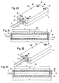
- the two plates 30 and 31 may be connected to each other by pressing. But there is also, as in the embodiment of FIGS. 20, 22 and 23 , the possibility of the two plates 30 and 31 by screws 45th or 49 and 50 to connect. In this case, the screws 45 may each be disposed in the corners of the heat sink 13/3 forming plates 30 and 31, as in Fig. 20 represented, or as in the embodiment of FIGS. 22 and 23 in which they are arranged in the longitudinal center.
- the heat sink 13/3 or the two heat sink 13/3 forming plates 30 and 31 are each provided with a length s which is greater than the length s1 of the load resistor 11/1, so that this with the required axial clearance between the cavity 37 in the vertical direction centrally projecting fixing in the form of dowel pins 47 and 48 or in the form of connecting screws 49 and 50 can be arranged.
- the two connecting screws 49 and 50 which also serve as fixing elements, arranged at a distance a from each other, that the load resistance 11/1 temperature-related unhindered can expand between, without changing its predetermined axial position.
Landscapes
- Engineering & Computer Science (AREA)
- Microelectronics & Electronic Packaging (AREA)
- Manufacturing & Machinery (AREA)
- Details Of Resistors (AREA)
- Control Of Electrical Variables (AREA)
- Superconductors And Manufacturing Methods Therefor (AREA)
- Semiconductor Integrated Circuits (AREA)
- Non-Adjustable Resistors (AREA)
- Casings For Electric Apparatus (AREA)
- Connection Of Plates (AREA)
- Mounting Components In General For Electric Apparatus (AREA)
- Cooling Or The Like Of Electrical Apparatus (AREA)
- Electrical Discharge Machining, Electrochemical Machining, And Combined Machining (AREA)
Applications Claiming Priority (1)
| Application Number | Priority Date | Filing Date | Title |
|---|---|---|---|
| DE202008014586U DE202008014586U1 (de) | 2008-11-03 | 2008-11-03 | Aluminium-Lastwiderstand |
Publications (3)
| Publication Number | Publication Date |
|---|---|
| EP2182529A2 true EP2182529A2 (fr) | 2010-05-05 |
| EP2182529A3 EP2182529A3 (fr) | 2010-07-28 |
| EP2182529B1 EP2182529B1 (fr) | 2011-04-13 |
Family
ID=40299483
Family Applications (2)
| Application Number | Title | Priority Date | Filing Date |
|---|---|---|---|
| EP09013450A Active EP2182529B1 (fr) | 2008-11-03 | 2009-10-24 | Résistance de charge en aluminium |
| EP09013457A Active EP2182528B1 (fr) | 2008-11-03 | 2009-10-26 | Dispositif de fixation d'une résistance de charge |
Family Applications After (1)
| Application Number | Title | Priority Date | Filing Date |
|---|---|---|---|
| EP09013457A Active EP2182528B1 (fr) | 2008-11-03 | 2009-10-26 | Dispositif de fixation d'une résistance de charge |
Country Status (4)
| Country | Link |
|---|---|
| EP (2) | EP2182529B1 (fr) |
| AT (2) | ATE505800T1 (fr) |
| DE (4) | DE202008014586U1 (fr) |
| DK (2) | DK2182529T3 (fr) |
Cited By (2)
| Publication number | Priority date | Publication date | Assignee | Title |
|---|---|---|---|---|
| CN103280283A (zh) * | 2013-04-24 | 2013-09-04 | 上海德程汇斯电气有限公司 | 一种耐高温制动电阻 |
| JP2014157891A (ja) * | 2013-02-15 | 2014-08-28 | Tamura Thermal Device Corp | ヒートシンク付抵抗器 |
Families Citing this family (8)
| Publication number | Priority date | Publication date | Assignee | Title |
|---|---|---|---|---|
| US7751370B2 (en) | 2001-07-13 | 2010-07-06 | Qualcomm Incorporated | Method and apparatus for forward link rate scheduling |
| DE102011001362A1 (de) * | 2010-08-11 | 2012-02-16 | Dbk David + Baader Gmbh | Bremswiderstand |
| DE102015213405A1 (de) * | 2015-07-16 | 2017-01-19 | Conti Temic Microelectronic Gmbh | Schaltungskomponententräger-Anordnung, Verfahren zu dessen Herstellung und Kombination mit einem Montagekörper |
| EP3401617A1 (fr) * | 2017-05-12 | 2018-11-14 | Mahle International GmbH | Dispositif de chauffage électrique |
| DE102017113600A1 (de) * | 2017-06-20 | 2018-12-20 | Vishay Electronic Gmbh | Leistungswiderstand |
| DE202018102531U1 (de) * | 2018-05-07 | 2018-05-22 | Türk & Hillinger GmbH | Heizpatrone mit Regelelement |
| TWD200403S (zh) | 2018-08-20 | 2019-10-21 | 德商斯泰格控股有限公司 | 換流器(二) |
| DE102018124985B4 (de) | 2018-10-10 | 2022-05-05 | Stego-Holding Gmbh | Temperiervorrichtung und System |
Citations (1)
| Publication number | Priority date | Publication date | Assignee | Title |
|---|---|---|---|---|
| DE202007014360U1 (de) | 2007-10-12 | 2009-02-26 | Türk & Hillinger GmbH | Aluminium-Heizwiderstand |
Family Cites Families (5)
| Publication number | Priority date | Publication date | Assignee | Title |
|---|---|---|---|---|
| GB1058537A (en) * | 1965-07-20 | 1967-02-15 | Dale Electronics | Improvements in or relating to electrical resistors |
| DE9405513U1 (de) * | 1994-03-31 | 1994-07-21 | Türk & Hillinger GmbH, 78532 Tuttlingen | Elektrischer Heizkörper mit Kühlelementen |
| JPH0831602A (ja) * | 1994-07-12 | 1996-02-02 | Tokai Konetsu Kogyo Co Ltd | 間接冷却式抵抗器 |
| JP2001185407A (ja) * | 1999-12-24 | 2001-07-06 | Seiden Techno Co Ltd | 電力用抵抗器とその抵抗素子及びそれらの製造方法 |
| US7012226B1 (en) * | 2004-06-02 | 2006-03-14 | Durex International Corporation | Cartridge heater with a release coating |
-
2008
- 2008-11-03 DE DE202008014586U patent/DE202008014586U1/de not_active Expired - Lifetime
-
2009
- 2009-03-26 DE DE202009004058U patent/DE202009004058U1/de not_active Expired - Lifetime
- 2009-10-24 DE DE502009000539T patent/DE502009000539D1/de active Active
- 2009-10-24 DK DK09013450.3T patent/DK2182529T3/da active
- 2009-10-24 AT AT09013450T patent/ATE505800T1/de active
- 2009-10-24 EP EP09013450A patent/EP2182529B1/fr active Active
- 2009-10-26 EP EP09013457A patent/EP2182528B1/fr active Active
- 2009-10-26 DE DE502009000500T patent/DE502009000500D1/de active Active
- 2009-10-26 AT AT09013457T patent/ATE504068T1/de active
- 2009-10-26 DK DK09013457.8T patent/DK2182528T3/da active
Patent Citations (1)
| Publication number | Priority date | Publication date | Assignee | Title |
|---|---|---|---|---|
| DE202007014360U1 (de) | 2007-10-12 | 2009-02-26 | Türk & Hillinger GmbH | Aluminium-Heizwiderstand |
Cited By (2)
| Publication number | Priority date | Publication date | Assignee | Title |
|---|---|---|---|---|
| JP2014157891A (ja) * | 2013-02-15 | 2014-08-28 | Tamura Thermal Device Corp | ヒートシンク付抵抗器 |
| CN103280283A (zh) * | 2013-04-24 | 2013-09-04 | 上海德程汇斯电气有限公司 | 一种耐高温制动电阻 |
Also Published As
| Publication number | Publication date |
|---|---|
| DE202008014586U1 (de) | 2009-01-29 |
| DK2182528T3 (da) | 2011-07-18 |
| ATE504068T1 (de) | 2011-04-15 |
| DE502009000539D1 (de) | 2011-05-26 |
| DE502009000500D1 (de) | 2011-05-12 |
| EP2182529A3 (fr) | 2010-07-28 |
| DK2182529T3 (da) | 2011-07-18 |
| DE202009004058U1 (de) | 2009-06-04 |
| ATE505800T1 (de) | 2011-04-15 |
| EP2182528B1 (fr) | 2011-03-30 |
| EP2182528A2 (fr) | 2010-05-05 |
| EP2182529B1 (fr) | 2011-04-13 |
| EP2182528A3 (fr) | 2010-07-28 |
Similar Documents
| Publication | Publication Date | Title |
|---|---|---|
| EP2182529B1 (fr) | Résistance de charge en aluminium | |
| DE2314168C3 (de) | Einstückiges Ankerelement für Stehbolzen | |
| EP0642141A1 (fr) | Parafoudre | |
| DE102009040809A1 (de) | Elektrische Heizvorrichtung und Verfahren zur Herstellung einer elektrischen Heizvorrichtung | |
| EP0545038A1 (fr) | Parafoudre | |
| DE3144901C2 (de) | Elektrisch isolierte Verbindung zwischen zwei gleichachsig angeordneten, stabförmigen Elementen aus Metall insbesondere Schraubendreher | |
| DE102009043526A1 (de) | Vorrichtung zur elektrischen Energiespeicherung | |
| EP0425981A2 (fr) | Bloc à canaux de chauffe | |
| DE3008287A1 (de) | Bolzen fuer schubstangen | |
| EP3047159B1 (fr) | Raccord de profilés et assemblage de profilés | |
| DE1933627A1 (de) | Verfahren zur Herstellung einer Verbindung einer Elektrodenspitze mit einer Elektrode | |
| DE3036498A1 (de) | Kunststoffprofilscharnier fuer schaltuschranktueren | |
| DE202007014360U1 (de) | Aluminium-Heizwiderstand | |
| DE19931306C2 (de) | Verfahren zur Herstellung von leichten keramischen Bauteilen sowie Bausatz zur Erstellung eines solchen leichten keramischen Bauteils | |
| DE1159075B (de) | Elektrischer Schaltapparat mit ausgepraegter Achse | |
| DE102004039300A1 (de) | Befestigungselement | |
| DE102009017806A1 (de) | Befestigungselement | |
| EP0927621B1 (fr) | Système à canal chaud, en particulier pour une machine à mouler par injection ou moule d'injection de matières plastiques | |
| DE102009056003B4 (de) | Elektrischer Widerstand | |
| DE9414208U1 (de) | Beschlagunterteil | |
| DE19737995A1 (de) | Bauelement | |
| DE20016611U1 (de) | Tür- und/oder Fensterprofil | |
| DE2550026C3 (de) | Schalter | |
| DE19952719A1 (de) | Isolator für eine Hochspannungsschaltanlage | |
| EP0340700B1 (fr) | Boîtier pour appareils de commutation en série |
Legal Events
| Date | Code | Title | Description |
|---|---|---|---|
| PUAI | Public reference made under article 153(3) epc to a published international application that has entered the european phase |
Free format text: ORIGINAL CODE: 0009012 |
|
| AK | Designated contracting states |
Kind code of ref document: A2 Designated state(s): AT BE BG CH CY CZ DE DK EE ES FI FR GB GR HR HU IE IS IT LI LT LU LV MC MK MT NL NO PL PT RO SE SI SK SM TR |
|
| AX | Request for extension of the european patent |
Extension state: AL BA RS |
|
| PUAL | Search report despatched |
Free format text: ORIGINAL CODE: 0009013 |
|
| AK | Designated contracting states |
Kind code of ref document: A3 Designated state(s): AT BE BG CH CY CZ DE DK EE ES FI FR GB GR HR HU IE IS IT LI LT LU LV MC MK MT NL NO PL PT RO SE SI SK SM TR |
|
| AX | Request for extension of the european patent |
Extension state: AL BA RS |
|
| RIC1 | Information provided on ipc code assigned before grant |
Ipc: H05B 3/44 20060101ALI20100618BHEP Ipc: H01C 17/22 20060101ALI20100618BHEP Ipc: H01C 1/08 20060101ALI20100618BHEP Ipc: H01C 1/084 20060101ALI20100618BHEP Ipc: H01C 3/20 20060101ALI20100618BHEP Ipc: H01C 1/036 20060101AFI20100303BHEP |
|
| GRAP | Despatch of communication of intention to grant a patent |
Free format text: ORIGINAL CODE: EPIDOSNIGR1 |
|
| 17P | Request for examination filed |
Effective date: 20101109 |
|
| GRAS | Grant fee paid |
Free format text: ORIGINAL CODE: EPIDOSNIGR3 |
|
| GRAA | (expected) grant |
Free format text: ORIGINAL CODE: 0009210 |
|
| AK | Designated contracting states |
Kind code of ref document: B1 Designated state(s): AT BE BG CH CY CZ DE DK EE ES FI FR GB GR HR HU IE IS IT LI LT LU LV MC MK MT NL NO PL PT RO SE SI SK SM TR |
|
| REG | Reference to a national code |
Ref country code: GB Ref legal event code: FG4D Free format text: NOT ENGLISH |
|
| REG | Reference to a national code |
Ref country code: CH Ref legal event code: EP |
|
| REG | Reference to a national code |
Ref country code: IE Ref legal event code: FG4D Free format text: LANGUAGE OF EP DOCUMENT: GERMAN |
|
| REF | Corresponds to: |
Ref document number: 502009000539 Country of ref document: DE Date of ref document: 20110526 Kind code of ref document: P |
|
| REG | Reference to a national code |
Ref country code: DE Ref legal event code: R096 Ref document number: 502009000539 Country of ref document: DE Effective date: 20110526 |
|
| REG | Reference to a national code |
Ref country code: DK Ref legal event code: T3 |
|
| REG | Reference to a national code |
Ref country code: NL Ref legal event code: VDEP Effective date: 20110413 |
|
| LTIE | Lt: invalidation of european patent or patent extension |
Effective date: 20110413 |
|
| PG25 | Lapsed in a contracting state [announced via postgrant information from national office to epo] |
Ref country code: HR Free format text: LAPSE BECAUSE OF FAILURE TO SUBMIT A TRANSLATION OF THE DESCRIPTION OR TO PAY THE FEE WITHIN THE PRESCRIBED TIME-LIMIT Effective date: 20110413 Ref country code: NO Free format text: LAPSE BECAUSE OF FAILURE TO SUBMIT A TRANSLATION OF THE DESCRIPTION OR TO PAY THE FEE WITHIN THE PRESCRIBED TIME-LIMIT Effective date: 20110713 Ref country code: PT Free format text: LAPSE BECAUSE OF FAILURE TO SUBMIT A TRANSLATION OF THE DESCRIPTION OR TO PAY THE FEE WITHIN THE PRESCRIBED TIME-LIMIT Effective date: 20110816 Ref country code: LT Free format text: LAPSE BECAUSE OF FAILURE TO SUBMIT A TRANSLATION OF THE DESCRIPTION OR TO PAY THE FEE WITHIN THE PRESCRIBED TIME-LIMIT Effective date: 20110413 Ref country code: SE Free format text: LAPSE BECAUSE OF FAILURE TO SUBMIT A TRANSLATION OF THE DESCRIPTION OR TO PAY THE FEE WITHIN THE PRESCRIBED TIME-LIMIT Effective date: 20110413 |
|
| REG | Reference to a national code |
Ref country code: IE Ref legal event code: FD4D |
|
| PG25 | Lapsed in a contracting state [announced via postgrant information from national office to epo] |
Ref country code: IS Free format text: LAPSE BECAUSE OF FAILURE TO SUBMIT A TRANSLATION OF THE DESCRIPTION OR TO PAY THE FEE WITHIN THE PRESCRIBED TIME-LIMIT Effective date: 20110813 Ref country code: SI Free format text: LAPSE BECAUSE OF FAILURE TO SUBMIT A TRANSLATION OF THE DESCRIPTION OR TO PAY THE FEE WITHIN THE PRESCRIBED TIME-LIMIT Effective date: 20110413 Ref country code: GR Free format text: LAPSE BECAUSE OF FAILURE TO SUBMIT A TRANSLATION OF THE DESCRIPTION OR TO PAY THE FEE WITHIN THE PRESCRIBED TIME-LIMIT Effective date: 20110714 Ref country code: CY Free format text: LAPSE BECAUSE OF FAILURE TO SUBMIT A TRANSLATION OF THE DESCRIPTION OR TO PAY THE FEE WITHIN THE PRESCRIBED TIME-LIMIT Effective date: 20110413 Ref country code: ES Free format text: LAPSE BECAUSE OF FAILURE TO SUBMIT A TRANSLATION OF THE DESCRIPTION OR TO PAY THE FEE WITHIN THE PRESCRIBED TIME-LIMIT Effective date: 20110724 Ref country code: LV Free format text: LAPSE BECAUSE OF FAILURE TO SUBMIT A TRANSLATION OF THE DESCRIPTION OR TO PAY THE FEE WITHIN THE PRESCRIBED TIME-LIMIT Effective date: 20110413 Ref country code: FI Free format text: LAPSE BECAUSE OF FAILURE TO SUBMIT A TRANSLATION OF THE DESCRIPTION OR TO PAY THE FEE WITHIN THE PRESCRIBED TIME-LIMIT Effective date: 20110413 |
|
| PG25 | Lapsed in a contracting state [announced via postgrant information from national office to epo] |
Ref country code: NL Free format text: LAPSE BECAUSE OF FAILURE TO SUBMIT A TRANSLATION OF THE DESCRIPTION OR TO PAY THE FEE WITHIN THE PRESCRIBED TIME-LIMIT Effective date: 20110413 |
|
| PG25 | Lapsed in a contracting state [announced via postgrant information from national office to epo] |
Ref country code: EE Free format text: LAPSE BECAUSE OF FAILURE TO SUBMIT A TRANSLATION OF THE DESCRIPTION OR TO PAY THE FEE WITHIN THE PRESCRIBED TIME-LIMIT Effective date: 20110413 Ref country code: IE Free format text: LAPSE BECAUSE OF FAILURE TO SUBMIT A TRANSLATION OF THE DESCRIPTION OR TO PAY THE FEE WITHIN THE PRESCRIBED TIME-LIMIT Effective date: 20110413 Ref country code: CZ Free format text: LAPSE BECAUSE OF FAILURE TO SUBMIT A TRANSLATION OF THE DESCRIPTION OR TO PAY THE FEE WITHIN THE PRESCRIBED TIME-LIMIT Effective date: 20110413 |
|
| PLBE | No opposition filed within time limit |
Free format text: ORIGINAL CODE: 0009261 |
|
| STAA | Information on the status of an ep patent application or granted ep patent |
Free format text: STATUS: NO OPPOSITION FILED WITHIN TIME LIMIT |
|
| PG25 | Lapsed in a contracting state [announced via postgrant information from national office to epo] |
Ref country code: RO Free format text: LAPSE BECAUSE OF FAILURE TO SUBMIT A TRANSLATION OF THE DESCRIPTION OR TO PAY THE FEE WITHIN THE PRESCRIBED TIME-LIMIT Effective date: 20110413 Ref country code: PL Free format text: LAPSE BECAUSE OF FAILURE TO SUBMIT A TRANSLATION OF THE DESCRIPTION OR TO PAY THE FEE WITHIN THE PRESCRIBED TIME-LIMIT Effective date: 20110413 Ref country code: SK Free format text: LAPSE BECAUSE OF FAILURE TO SUBMIT A TRANSLATION OF THE DESCRIPTION OR TO PAY THE FEE WITHIN THE PRESCRIBED TIME-LIMIT Effective date: 20110413 |
|
| 26N | No opposition filed |
Effective date: 20120116 |
|
| BERE | Be: lapsed |
Owner name: TURK + HILLINGER G.M.B.H. Effective date: 20111031 |
|
| REG | Reference to a national code |
Ref country code: DE Ref legal event code: R097 Ref document number: 502009000539 Country of ref document: DE Effective date: 20120116 |
|
| PG25 | Lapsed in a contracting state [announced via postgrant information from national office to epo] |
Ref country code: IT Free format text: LAPSE BECAUSE OF FAILURE TO SUBMIT A TRANSLATION OF THE DESCRIPTION OR TO PAY THE FEE WITHIN THE PRESCRIBED TIME-LIMIT Effective date: 20110413 Ref country code: MC Free format text: LAPSE BECAUSE OF NON-PAYMENT OF DUE FEES Effective date: 20111031 |
|
| REG | Reference to a national code |
Ref country code: FR Ref legal event code: ST Effective date: 20120629 |
|
| PG25 | Lapsed in a contracting state [announced via postgrant information from national office to epo] |
Ref country code: BE Free format text: LAPSE BECAUSE OF NON-PAYMENT OF DUE FEES Effective date: 20111031 |
|
| PG25 | Lapsed in a contracting state [announced via postgrant information from national office to epo] |
Ref country code: FR Free format text: LAPSE BECAUSE OF NON-PAYMENT OF DUE FEES Effective date: 20111102 |
|
| PG25 | Lapsed in a contracting state [announced via postgrant information from national office to epo] |
Ref country code: MT Free format text: LAPSE BECAUSE OF FAILURE TO SUBMIT A TRANSLATION OF THE DESCRIPTION OR TO PAY THE FEE WITHIN THE PRESCRIBED TIME-LIMIT Effective date: 20110413 Ref country code: MK Free format text: LAPSE BECAUSE OF FAILURE TO SUBMIT A TRANSLATION OF THE DESCRIPTION OR TO PAY THE FEE WITHIN THE PRESCRIBED TIME-LIMIT Effective date: 20110413 |
|
| PG25 | Lapsed in a contracting state [announced via postgrant information from national office to epo] |
Ref country code: SM Free format text: LAPSE BECAUSE OF FAILURE TO SUBMIT A TRANSLATION OF THE DESCRIPTION OR TO PAY THE FEE WITHIN THE PRESCRIBED TIME-LIMIT Effective date: 20110413 |
|
| PG25 | Lapsed in a contracting state [announced via postgrant information from national office to epo] |
Ref country code: LU Free format text: LAPSE BECAUSE OF NON-PAYMENT OF DUE FEES Effective date: 20111024 |
|
| PG25 | Lapsed in a contracting state [announced via postgrant information from national office to epo] |
Ref country code: BG Free format text: LAPSE BECAUSE OF FAILURE TO SUBMIT A TRANSLATION OF THE DESCRIPTION OR TO PAY THE FEE WITHIN THE PRESCRIBED TIME-LIMIT Effective date: 20110713 |
|
| PG25 | Lapsed in a contracting state [announced via postgrant information from national office to epo] |
Ref country code: TR Free format text: LAPSE BECAUSE OF FAILURE TO SUBMIT A TRANSLATION OF THE DESCRIPTION OR TO PAY THE FEE WITHIN THE PRESCRIBED TIME-LIMIT Effective date: 20110413 |
|
| PG25 | Lapsed in a contracting state [announced via postgrant information from national office to epo] |
Ref country code: HU Free format text: LAPSE BECAUSE OF FAILURE TO SUBMIT A TRANSLATION OF THE DESCRIPTION OR TO PAY THE FEE WITHIN THE PRESCRIBED TIME-LIMIT Effective date: 20110413 |
|
| REG | Reference to a national code |
Ref country code: CH Ref legal event code: PL |
|
| GBPC | Gb: european patent ceased through non-payment of renewal fee |
Effective date: 20131024 |
|
| PG25 | Lapsed in a contracting state [announced via postgrant information from national office to epo] |
Ref country code: CH Free format text: LAPSE BECAUSE OF NON-PAYMENT OF DUE FEES Effective date: 20131031 Ref country code: LI Free format text: LAPSE BECAUSE OF NON-PAYMENT OF DUE FEES Effective date: 20131031 Ref country code: GB Free format text: LAPSE BECAUSE OF NON-PAYMENT OF DUE FEES Effective date: 20131024 |
|
| REG | Reference to a national code |
Ref country code: AT Ref legal event code: MM01 Ref document number: 505800 Country of ref document: AT Kind code of ref document: T Effective date: 20141024 |
|
| PG25 | Lapsed in a contracting state [announced via postgrant information from national office to epo] |
Ref country code: AT Free format text: LAPSE BECAUSE OF NON-PAYMENT OF DUE FEES Effective date: 20141024 |
|
| PGFP | Annual fee paid to national office [announced via postgrant information from national office to epo] |
Ref country code: DE Payment date: 20251125 Year of fee payment: 17 |
|
| PGFP | Annual fee paid to national office [announced via postgrant information from national office to epo] |
Ref country code: DK Payment date: 20251023 Year of fee payment: 17 |