EP2182616B1 - Moteur à courant continu sans balai - Google Patents
Moteur à courant continu sans balai Download PDFInfo
- Publication number
- EP2182616B1 EP2182616B1 EP09013330.7A EP09013330A EP2182616B1 EP 2182616 B1 EP2182616 B1 EP 2182616B1 EP 09013330 A EP09013330 A EP 09013330A EP 2182616 B1 EP2182616 B1 EP 2182616B1
- Authority
- EP
- European Patent Office
- Prior art keywords
- stator
- line
- another
- sensor mount
- insulation displacement
- Prior art date
- Legal status (The legal status is an assumption and is not a legal conclusion. Google has not performed a legal analysis and makes no representation as to the accuracy of the status listed.)
- Active
Links
Images




Classifications
-
- H—ELECTRICITY
- H02—GENERATION; CONVERSION OR DISTRIBUTION OF ELECTRIC POWER
- H02K—DYNAMO-ELECTRIC MACHINES
- H02K3/00—Details of windings
- H02K3/46—Fastening of windings on the stator or rotor structure
- H02K3/52—Fastening salient pole windings or connections thereto
- H02K3/521—Fastening salient pole windings or connections thereto applicable to stators only
- H02K3/522—Fastening salient pole windings or connections thereto applicable to stators only for generally annular cores with salient poles
-
- H—ELECTRICITY
- H02—GENERATION; CONVERSION OR DISTRIBUTION OF ELECTRIC POWER
- H02K—DYNAMO-ELECTRIC MACHINES
- H02K2203/00—Specific aspects not provided for in the other groups of this subclass relating to the windings
- H02K2203/03—Machines characterised by the wiring boards, i.e. printed circuit boards or similar structures for connecting the winding terminations
Definitions
- the invention relates to a brushless DC motor.
- the previously used brushless DC motors usually work with Hall sensors, which detect the rotor position, so that the commutations of the electric motor can take place at the right times.
- the torque of brushless DC motors strongly depends on whether the Hall sensors used to drive the stator windings are optimal for the rotor and the driven winding.
- the Hall sensors are usually glued to the intended locations on the stator, wherein the electrical contacts of the Hall sensors must be soldered to the control electronics. The orientation, the bonding and However, the soldering of the Hall sensors is associated with a considerable effort.
- a brushless DC motor which is designed as an external rotor motor and has a rotor having permanent magnets, which rotates in the commutation changing magnetic field of a rotor gripped by the rotor.
- This magnetic field is generated by a winding system in the circumferential direction spaced apart and applied to an insulating body line windings, being assigned to control the spaced apart electrical line windings of the winding system provided in the stator control electronics with the phases of the winding system associated non-contact rotary position sensors.
- These rotary position sensors are arranged on a common, designed as a printed circuit board sensor carrier, which is fastened to an end face of the stator.
- the circuit boards is fixed by means of a positioning aid in a terminal block.
- the terminal block is in turn positioned relative to the stator by means of guides.
- the printed circuit board carrying the rotary position sensors, on the one hand, and the terminal block intended for receiving the printed circuit board are separate components per se, the previously known DC motor is designed in several parts and correspondingly complex in this area. This also adds the tolerances of these components, so that the desired optimum positioning of the rotary position sensors can only be achieved approximately. Due to the multi-part in this sensitive area of the prior art DC motor is associated with a considerable effort in construction and manufacturing.
- a brushless DC motor in which the control electronics is housed in a container which is positioned by means of insulation displacement connectors relative to the stator and connected to the winding thereof.
- the control electronics and their associated rotary position sensors are provided on an annular plate, which are encapsulated in an electrically insulating material which fills the container.
- the control electronics, the rotational position sensors and the positioning required for their positioning relative to the stator positioning means are designed in several parts and require a significant design and manufacturing costs.
- the container carrying the insulation displacement connector on the one hand and the board located inside the container on the other hand are positioned in position relative to each other so that the positioning of the on-board rotational position sensors is fixed with respect to the stator.
- the DC motor has a rotor which has permanent magnets and rotates in the commutation alternating magnetic field of a stator.
- the magnetic field can be generated by a winding system which is formed in the circumferential direction spaced apart and wound on an insulating body line windings.
- the previously known DC motor has a commutation circuit serving as control electronics, the non-contact rotary position sensors associated with the phases of the winding system Has. These rotary position sensors are arranged on a common sensor carrier, which can also be designed as a, the rotary position sensors supporting sensor board.
- the control electronics is connected to the leads of the spaced-apart line windings via electrical contacts, which are provided on the sensor carrier and designed as insulation displacement terminals.
- the commutation circuit is arranged together with a stator winding substantially in a single space, which is why cooling of the stator winding and the commutation should be limited guaranteed.
- the DE 100 45 596 A1 be arranged in the end shield of the commutation circuit of the prior art DC motor. In the DE 100 45 596 A1 is not mentioned in any word how to ensure a positionally accurate position of the rotary position sensors with respect to the stator.
- control electronics and their associated rotary position sensors are provided on an annular plate, which are encapsulated in an electrically insulating material which fills the container.
- control electronics the rotary position sensors and required for their positioning relative to the stator positioning aids designed in several parts and require a considerable design and manufacturing effort.
- the container supporting the insulation displacement connector on the one hand and the board located inside the container on the other hand should be positioned in position relative to each other so that the positioning of the rotary position sensors located on the board is fixed with respect to the stator.
- the control electronics of the DC motor according to the invention is connected to the leads of the spaced-apart line windings via electrical contacts, which are designed as positioning aids. These, designed as a positioning aid electrical contacts are provided on a sensor carrier, which is designed as a, the rotary position sensors supporting sensor board. Since the positioning are configured as insulation displacement terminals and as these insulation displacement terminals contact the leads of the spaced wire windings in the area of the line sections located in the defined conductor guides of the stator, a positionally correct positioning between the rotational position sensors provided on the sensor board on the one hand and the stator on the other hand ensured.
- the DC motor according to the invention is characterized by its low cost in design and manufacturing. Since a manual alignment of the rotary position sensors relative to the stator, the bonding of these rotary position sensors in the stator and the soldering of the rotary position sensors with the other electrical components of the DC motor are thus avoided, the DC motor according to the invention can be produced with little effort, this DC motor due to the always exact alignment the rotary position sensors with respect to the stator windings provided on the stator characterized by a correspondingly high torque.
- the DC motor according to the invention has on the at least one, the sensor carrier associated end face of its stator crown-shaped projections, of which at least individual projections are formed as cable guides.
- the electrical lines can be performed on the circumference of the stator.
- the sensor carrier can be fastened in a simple manner and at the same time positionally accurate on the stator, wherein at the same time the electrical connection between the control electronics on the one hand and the other electrical components of the DC motor according to the invention is made.
- stator has a sleeve-shaped stator housing, on whose front side in each case an insulation cap is provided, of which at least one insulation cap is designed for connection to a sensor carrier, wherein the stator on both sides provided insulation caps between them spaced from each other Line windings of the stator associated multi-phase winding system wear.
- each line guide has intersecting guide openings, of which a guide opening for receiving a contacting of the insulation displacement terminal section is determined and of which another, open front guide opening for inserting a respective insulation displacement terminal is configured.
- the leads which are assigned to the spaced-apart line windings can be guided particularly easily in the area of the stator housing and the sensor carrier can be fastened to the stator end face with little effort if the guide openings provided for receiving the line section and / or for inserting the insulation displacement slit of each line guide are slot-shaped are.
- a preferred embodiment according to the invention provides that the stator on its at least one, the sensor carrier associated end face crown-shaped configured projections, of which at least individual projections are formed as cable guides. By meandering laying the spaced apart line windings associated feed lines around the individual projections around the electrical wires can lead to the circumference of the stator. If at least individual projections are also formed as cable guides, the sensor carrier can be fixed in a simple manner and at the same time positionally accurate on the stator, at the same time the electrical connection between the control electronics on the one hand and the other electrical components of the DC motor according to the invention is made.
- Fig. 8 the stator 1 of a brushless DC motor is shown in a perspective view, which DC motor can be used for example as a pump drive in particular for a diaphragm pump.
- the DC motor is associated with a rotor, not shown here, which carries permanent magnets on its outer circumference.
- the rotor is driven by the magnetic field of the annular stator 1 which changes as a result of commutation, ie by changing the current direction, with the rotor rotating in the stator 1 which surrounds it annularly.
- the magnetic field can be generated by a multi-phase winding system 2 with line windings 3 which are spaced apart from one another in the circumferential direction and which are wound up on an insulator body indicated as a whole by 4.
- an electronic control system for controlling the spaced-apart line windings of the line system provided in the stator, which comprises the phases of the winding system 2 associated non-contact rotary position sensors 5.
- These rotary position sensors 5 may be formed, for example, as Hall sensors.
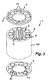
- FIG. 1 to 7 are the individual manufacturing steps for making the in Fig. 8 shown stator 1 shown.
- the insulating body of the stator 1, indicated as a whole by 4 has a solid, sleeve-shaped stator housing 20 which carries winding projections 6 on its housing inner circumference, which delimit grooves 7 oriented in the longitudinal direction between them.
- the grooves 7 limiting wall inner circumference is in each case lined by a groove 7 arranged in the grooves isolation 8.
- annular insulation caps 9 are placed, which have pocket-shaped recesses 10 in the area of the grooves 7 and groove insulation 8 on the inner peripheral side.
- These recesses 10 of the insulation caps 9 are also separated by inner peripheral side spaced-apart winding projections 11.
- the rotary position sensors 5 are arranged on a sensor carrier 13 and project in the direction of the stator 1.
- the rotary position sensors 5 are arranged on a sensor carrier 13 and project in the direction of the stator 1.
- This sensor carrier 13 is designed as a, preferably all rotary position sensors 5 supporting sensor board. Between the at least one sensor carrier 13 and the adjacent stator end side cooperating positioning aids are provided which determine the relative position of the stator 1 with respect to the sensor carrier 13 and the rotary position sensors 5 arranged thereon.
- Fig. 4 to 7 1 illustrates that the part of the control electronics located on the sensor carrier 13 and comprising the rotary position sensors 5 is connected to the leads 15 of the spaced-apart line windings 3 via electrical contacts which are designed as positioning aids.
- the electrical contacts designed as positioning aids are provided on the sensor carrier 13.
- the contacts provided on the sensor carrier 13 and serving as positioning aids are designed here as insulation displacement terminals 14.
- each line guide 16 has intersecting and slot-shaped guide openings 17, 18, of which a guide opening 17 for receiving a contacted by the insulation displacement terminal 14 line section is determined and of which another, open front guide opening 18 for insertion of a cutting terminal 14 is configured.
- Fig. 7 It is shown that by simply plugging on the sensor carrier 13 protruding insulation displacement terminals 14 on the wiring 16 of the stator 1 and by inserting these insulation displacement terminals 14 in the guide slots 17 provided on the guide slots 17 can be easily connected to the stator 1 and electrically contacted.
- stator has a projection 16, 19 which is crown-shaped at its at least one end face associated with the sensor carrier 13 has, of which at least individual projections are formed as wiring 16.
- the stator 1 shown here has a sleeve-shaped stator housing 20, on the front sides of the insulation caps 9 are provided. Of these, the sensor carrier 13 associated insulation cap 9 is formed for connection to the sensor carrier 13, wherein the stator 1 on both sides provided insulation caps 9 carry between them the spaced line windings 3 of the stator 1 associated multi-phase winding system 2.
- the stator 1 shown here and intended for a brushless DC motor can therefore be manufactured cost-effectively in a simple manner in an automated production process.
Landscapes
- Engineering & Computer Science (AREA)
- Power Engineering (AREA)
- Brushless Motors (AREA)
- Insulation, Fastening Of Motor, Generator Windings (AREA)
Claims (3)
- Moteur à courant continu sans balais,a) qui possède un rotor présentant des aimants permanents, lequel tourne dans le champ magnétique alternant par commutation d'un stator (1),b) lequel champ magnétique peut être produit par un système d'enroulements formé d'enroulements de conducteurs (3) espacés les uns des autres en direction circonférentielle et disposés sur un corps isolant (4), sachant quec) pour commander les enroulements de conducteurs électriques (3) espacés les uns des autres du système d'enroulements prévu dans le stator (1), il est prévu une électronique de commande avecd) des capteurs de position de rotation sans contact (5) associés aux phases du système d'enroulements (2),e) qui sont disposés sur un support de capteurs commun (13), lequel support de capteurs (13) peut être fixé à une face d'extrémité du stator (1), etf) entre le support de capteurs (13) et la face d'extrémité de stator sont prévus des moyens de positionnement qui coopèrent entre eux et qui définissent la position relative du stator (1) par rapport au support de capteurs (13) et aux capteurs de position de rotation (5) disposés sur celui-ci,g) l'électronique de commande étant reliée aux lignes d'alimentation (15) des enroulements de conducteurs (3) espacés les uns des autres par des contacts électriques qui sont configurés comme des moyens de positionnement,h) les contacts électriques configurés comme des moyens de positionnement étant prévus sur le support de capteurs (13) et configurés comme des bornes autodénudantes (14),i) le support de capteurs (13) étant configuré comme une platine de capteurs portant les capteurs de position de rotation (12), etj) les lignes d'alimentation (15) des enroulements de conducteurs (3) espacés les uns des autres avec leurs portions de ligne contactées par les bornes autodénudantes (14) étant maintenues dans des guides de ligne (16) à des positions définies du stator (1), sachant quek) le stator (1) possède un boîtier de stator (20) en forme de douille, à chaque face d'extrémité duquel est prévu un chapeau isolant (9), au moins un chapeau isolant (9) étant configuré pour être relié à un support de capteurs (13),l) les chapeaux isolants (9) prévus des deux côtés sur le stator (1) portent entre eux les enroulements de conducteurs (3) espacés les uns des autres du système d'enroulements polyphasé (2) associé au stator (1), etm) sur au moins un chapeau isolant (9), la face d'extrémité associée au support de capteurs (13) présente des saillies (16, 19) en forme de couronne pour la pose en méandres des lignes d'alimentation associées aux enroulements de conducteurs espacés les uns des autres autour des différentes saillies (16, 19), au moins certaines saillies (16, 19) étant configurées comme des guides de ligne (16).
- Moteur à courant continu selon la revendication 1, caractérisé en ce que chaque guide de ligne (16) présente des ouvertures de guidage (17, 18) se croisant l'une l'autre, dont une ouverture de guidage (17) est destinée à recevoir une portion de ligne contactée par la borne autodénudante (14) et dont une autre ouverture de guidage (18), ouverte du côté frontal, est configurée pour l'introduction d'une borne autodénudante (14).
- Moteur à courant continu selon la revendication 2, caractérisé en ce que les ouvertures de guidage (17, 18) prévues pour recevoir la portion de ligne et/ou pour l'introduction de la borne autodénudante (14) sont configurées en forme de fente.
Applications Claiming Priority (1)
| Application Number | Priority Date | Filing Date | Title |
|---|---|---|---|
| DE102008055731.5A DE102008055731B4 (de) | 2008-11-04 | 2008-11-04 | Bürstenloser Gleichstrommotor |
Publications (3)
| Publication Number | Publication Date |
|---|---|
| EP2182616A2 EP2182616A2 (fr) | 2010-05-05 |
| EP2182616A3 EP2182616A3 (fr) | 2011-03-02 |
| EP2182616B1 true EP2182616B1 (fr) | 2014-11-19 |
Family
ID=41651509
Family Applications (1)
| Application Number | Title | Priority Date | Filing Date |
|---|---|---|---|
| EP09013330.7A Active EP2182616B1 (fr) | 2008-11-04 | 2009-10-22 | Moteur à courant continu sans balai |
Country Status (4)
| Country | Link |
|---|---|
| US (1) | US8466590B2 (fr) |
| EP (1) | EP2182616B1 (fr) |
| CN (1) | CN201541194U (fr) |
| DE (1) | DE102008055731B4 (fr) |
Cited By (1)
| Publication number | Priority date | Publication date | Assignee | Title |
|---|---|---|---|---|
| FR3163129A1 (fr) * | 2024-06-10 | 2025-12-12 | Skf Magnetic Mechatronics | Support de routage pour actionneur radial et module de palier magnetique associe |
Families Citing this family (26)
| Publication number | Priority date | Publication date | Assignee | Title |
|---|---|---|---|---|
| JP2011167024A (ja) * | 2010-02-15 | 2011-08-25 | Minebea Co Ltd | Dcブラシレスモータ |
| JP2013088349A (ja) * | 2011-10-20 | 2013-05-13 | Alps Green Devices Co Ltd | 電流センサ |
| US8766578B2 (en) | 2012-02-27 | 2014-07-01 | Canadian Space Agency | Method and apparatus for high velocity ripple suppression of brushless DC motors having limited drive/amplifier bandwidth |
| JP5865767B2 (ja) * | 2012-04-09 | 2016-02-17 | 日立オートモティブシステムズ株式会社 | 車載用回転電機および電動パワーステアリング装置 |
| JP2014003799A (ja) * | 2012-06-18 | 2014-01-09 | Sanyo Denki Co Ltd | ブラシレスモータ |
| DE102012211183A1 (de) * | 2012-06-28 | 2014-01-02 | Robert Bosch Gmbh | Elektrowerkzeugmaschine |
| DE202012012647U1 (de) * | 2012-12-21 | 2013-10-17 | Robert Bosch Gmbh | Elektrische Maschine mit einem Stator und einem Rator |
| ITBS20130104A1 (it) * | 2013-07-17 | 2015-01-18 | I M E S P A Ind Motori El Ettrici | Gruppo motore |
| JP5977311B2 (ja) * | 2014-10-27 | 2016-08-24 | ファナック株式会社 | コイル固定部品を備えた固定子及び該固定子を備えた電動機 |
| US10211695B2 (en) | 2015-02-27 | 2019-02-19 | Brose Fahrzeugteile Gmbh & Co. Kommanditgesellschaft, Wuerzburg | Stator component group for an electric motor |
| DE102015217017B4 (de) * | 2015-09-04 | 2024-11-28 | Brose Fahrzeugteile SE & Co. Kommanditgesellschaft, Würzburg | Statorbaugruppe für einen Elektromotor |
| US9933906B2 (en) | 2016-03-28 | 2018-04-03 | Synaptics Incorporated | Capacitive sensing using discrete lighting elements |
| AU2017240597B2 (en) | 2016-03-30 | 2019-07-25 | Milwaukee Electric Tool Corporation | Brushless motor for a power tool |
| DE102016224526B4 (de) | 2016-12-08 | 2025-07-03 | Brose Fahrzeugteile SE & Co. Kommanditgesellschaft, Würzburg | Stator einer elektrischen Maschine, elektrische Maschine sowie Verlege- und Kontakteinrichtung für eine elektrische Maschine |
| WO2019036461A1 (fr) * | 2017-08-15 | 2019-02-21 | Quanten Technologies, Inc. | Barres de connexion destinées à un système de moteur |
| DE102017216075A1 (de) * | 2017-09-12 | 2019-03-14 | Robert Bosch Gmbh | Stator für eine elektrische Maschine, eine elektrische Maschine und Verfahren zum Herstellen eines solchen Stators |
| DE102017216084A1 (de) | 2017-09-12 | 2019-03-14 | Robert Bosch Gmbh | Stator für eine elektrische Maschine, eine elektrische Maschine und Verfahren zum Herstellen eines solchen Stators |
| DE102017219861A1 (de) * | 2017-11-08 | 2019-05-09 | Robert Bosch Gmbh | Schneid-Klemm-Verbindung, sowie Stator für eine elektrische Maschine und eine elektrische Maschine umfassend eine Schneid-Klemm-Verbindung und Verfahren zum Herstellen eines solchen Stators |
| DE102018217852B4 (de) * | 2018-10-18 | 2025-10-23 | Bühler Motor GmbH | Gleichstrommotor und Verfahren zur Herstellung eines Gleichstrommotors |
| KR102241110B1 (ko) * | 2019-12-05 | 2021-04-19 | 주식회사 코아비스 | 모터 및 이를 포함한 전동식 펌프 |
| GB2613880B (en) * | 2021-12-17 | 2024-05-08 | Eta Green Power Ltd | A rotor position sensor system for a slotless motor |
| GB2625947B (en) * | 2021-12-17 | 2024-11-27 | Eta Green Power Ltd | A rotor position sensor system for a slotless motor |
| WO2023228551A1 (fr) * | 2022-05-27 | 2023-11-30 | パナソニックIpマネジメント株式会社 | Borne de connexion, ensemble de stator ainsi que procédé de fabrication de celui-ci, et moteur électrique |
| DE102022214179A1 (de) | 2022-12-21 | 2024-06-27 | Robert Bosch Gesellschaft mit beschränkter Haftung | Stator für eine elektrische Maschine, sowie eine elektrische Maschine aufweisend ein Stator, und Verfahren zum Herstellen eines Stators |
| AU2024230434A1 (en) * | 2023-03-02 | 2025-09-11 | H3X Technologies Inc. | Thermal cap for stator winding |
| DE102023116314A1 (de) * | 2023-06-21 | 2024-12-24 | Minebea Mitsumi Inc. | Motorvorrichtung |
Family Cites Families (8)
| Publication number | Priority date | Publication date | Assignee | Title |
|---|---|---|---|---|
| JPH10304605A (ja) * | 1997-04-24 | 1998-11-13 | Toshiba Corp | 直流モータ |
| DE10045596B4 (de) | 2000-09-15 | 2004-07-01 | Bühler Motor GmbH | Pumpe mit einem elektronisch kommutierten Gleichstrommotor |
| GB0130602D0 (en) | 2001-12-21 | 2002-02-06 | Johnson Electric Sa | Brushless D.C. motor |
| CN1323787C (zh) * | 2002-02-04 | 2007-07-04 | 密尔沃基电动工具公司 | 包含开关磁阻电动机的电动装置 |
| EP1342465B1 (fr) | 2002-03-05 | 2011-10-19 | Kao Corporation | Teinture pour cheveux sous forme de mousse et appareil de décharge |
| US7135799B2 (en) * | 2003-03-19 | 2006-11-14 | Pacsci Motion Control, Inc. | Method for winding a stator of multi-phase motors |
| JP4496010B2 (ja) * | 2004-05-20 | 2010-07-07 | 株式会社東芝 | モータ |
| DE202006012075U1 (de) | 2006-08-04 | 2007-12-27 | Ebm-Papst Mulfingen Gmbh & Co. Kg | Stator mit Schaltscheibe |
-
2008
- 2008-11-04 DE DE102008055731.5A patent/DE102008055731B4/de not_active Expired - Fee Related
-
2009
- 2009-10-22 EP EP09013330.7A patent/EP2182616B1/fr active Active
- 2009-11-03 US US12/611,175 patent/US8466590B2/en active Active
- 2009-11-04 CN CN2009202681098U patent/CN201541194U/zh not_active Expired - Lifetime
Cited By (1)
| Publication number | Priority date | Publication date | Assignee | Title |
|---|---|---|---|---|
| FR3163129A1 (fr) * | 2024-06-10 | 2025-12-12 | Skf Magnetic Mechatronics | Support de routage pour actionneur radial et module de palier magnetique associe |
Also Published As
| Publication number | Publication date |
|---|---|
| US20100109458A1 (en) | 2010-05-06 |
| DE102008055731B4 (de) | 2014-07-31 |
| EP2182616A3 (fr) | 2011-03-02 |
| EP2182616A2 (fr) | 2010-05-05 |
| DE102008055731A1 (de) | 2010-05-12 |
| US8466590B2 (en) | 2013-06-18 |
| CN201541194U (zh) | 2010-08-04 |
Similar Documents
| Publication | Publication Date | Title |
|---|---|---|
| EP2182616B1 (fr) | Moteur à courant continu sans balai | |
| EP3078099B1 (fr) | Stator pour moteur à courant continu à commutation électronique | |
| DE60119051T2 (de) | Elektromotor | |
| DE102016224526B4 (de) | Stator einer elektrischen Maschine, elektrische Maschine sowie Verlege- und Kontakteinrichtung für eine elektrische Maschine | |
| DE102006034991B4 (de) | Elektrische Servolenkungsvorrichtung | |
| EP0220447B1 (fr) | Moteur électrique, en particulier moteur à rotor entourant le stator et à inducteur à aimants permanents | |
| DE112013006336B4 (de) | Verbindungsanschluss, Verbindungsanschlusseinheit und Motor | |
| EP2584672B1 (fr) | Elément de boîtier pour une machine électrique | |
| EP1062720B1 (fr) | Circuit pour la connexion d'enroulements de stator d'un moteur sans balais a commutation electronique | |
| DE112005000816T5 (de) | Bürstenloser Motor | |
| EP1617543A2 (fr) | Dispositif à placer des isolants dans les encoches d'un stator | |
| EP3939148B1 (fr) | Dispositif d'entraînement à moteur électrique sans balais | |
| DE102017104624A1 (de) | Ständer, Motor mit demselben und Verfahren zum Herstellen desselben | |
| WO2004114502A1 (fr) | Machine electrique comprenant un support de circuit | |
| DE102006021247B4 (de) | Elektromotor | |
| DE112010006096T5 (de) | Stator und mit diesem Stator ausgerüstete rotierende elektrische Maschine | |
| DE2800886A1 (de) | Gleichstrommotor | |
| DE112005000752T5 (de) | Bürstenloser Motor | |
| WO2019052782A1 (fr) | Stator d'une machine électrique, machine électrique et procédé de fabrication d'un tel stator | |
| EP0285048B1 (fr) | Moteur à courant continu sans collecteur commuté électroniquement | |
| EP1648072A2 (fr) | Stator d'une machine électrique | |
| DE102004050374A1 (de) | Elektrische Maschine, insbesondere Gleichstrommotor | |
| DE202008014658U1 (de) | Bürstenloser Gleichstrommotor | |
| DE10130139C1 (de) | Flansch für einen Elektromotor, insbesondere für einen elektronisch kommutierten Gleichstrommotor | |
| EP1964245B1 (fr) | Plaque d'extrémité de stator pour un moteur à collecteur et moteur à collecteur |
Legal Events
| Date | Code | Title | Description |
|---|---|---|---|
| PUAI | Public reference made under article 153(3) epc to a published international application that has entered the european phase |
Free format text: ORIGINAL CODE: 0009012 |
|
| AK | Designated contracting states |
Kind code of ref document: A2 Designated state(s): AT BE BG CH CY CZ DE DK EE ES FI FR GB GR HR HU IE IS IT LI LT LU LV MC MK MT NL NO PL PT RO SE SI SK SM TR |
|
| AX | Request for extension of the european patent |
Extension state: AL BA RS |
|
| PUAL | Search report despatched |
Free format text: ORIGINAL CODE: 0009013 |
|
| AK | Designated contracting states |
Kind code of ref document: A3 Designated state(s): AT BE BG CH CY CZ DE DK EE ES FI FR GB GR HR HU IE IS IT LI LT LU LV MC MK MT NL NO PL PT RO SE SI SK SM TR |
|
| AX | Request for extension of the european patent |
Extension state: AL BA RS |
|
| 17P | Request for examination filed |
Effective date: 20110729 |
|
| 17Q | First examination report despatched |
Effective date: 20131119 |
|
| GRAP | Despatch of communication of intention to grant a patent |
Free format text: ORIGINAL CODE: EPIDOSNIGR1 |
|
| INTG | Intention to grant announced |
Effective date: 20140730 |
|
| GRAS | Grant fee paid |
Free format text: ORIGINAL CODE: EPIDOSNIGR3 |
|
| GRAA | (expected) grant |
Free format text: ORIGINAL CODE: 0009210 |
|
| AK | Designated contracting states |
Kind code of ref document: B1 Designated state(s): AT BE BG CH CY CZ DE DK EE ES FI FR GB GR HR HU IE IS IT LI LT LU LV MC MK MT NL NO PL PT RO SE SI SK SM TR |
|
| REG | Reference to a national code |
Ref country code: GB Ref legal event code: FG4D Free format text: NOT ENGLISH |
|
| REG | Reference to a national code |
Ref country code: CH Ref legal event code: EP |
|
| REG | Reference to a national code |
Ref country code: AT Ref legal event code: REF Ref document number: 697516 Country of ref document: AT Kind code of ref document: T Effective date: 20141215 |
|
| REG | Reference to a national code |
Ref country code: IE Ref legal event code: FG4D Free format text: LANGUAGE OF EP DOCUMENT: GERMAN |
|
| REG | Reference to a national code |
Ref country code: CH Ref legal event code: NV Representative=s name: HANS RUDOLF GACHNANG PATENTANWALT, CH Ref country code: DE Ref legal event code: R096 Ref document number: 502009010236 Country of ref document: DE Effective date: 20141231 |
|
| REG | Reference to a national code |
Ref country code: NL Ref legal event code: VDEP Effective date: 20141119 |
|
| REG | Reference to a national code |
Ref country code: LT Ref legal event code: MG4D |
|
| PG25 | Lapsed in a contracting state [announced via postgrant information from national office to epo] |
Ref country code: NL Free format text: LAPSE BECAUSE OF FAILURE TO SUBMIT A TRANSLATION OF THE DESCRIPTION OR TO PAY THE FEE WITHIN THE PRESCRIBED TIME-LIMIT Effective date: 20141119 Ref country code: NO Free format text: LAPSE BECAUSE OF FAILURE TO SUBMIT A TRANSLATION OF THE DESCRIPTION OR TO PAY THE FEE WITHIN THE PRESCRIBED TIME-LIMIT Effective date: 20150219 Ref country code: IS Free format text: LAPSE BECAUSE OF FAILURE TO SUBMIT A TRANSLATION OF THE DESCRIPTION OR TO PAY THE FEE WITHIN THE PRESCRIBED TIME-LIMIT Effective date: 20150319 Ref country code: ES Free format text: LAPSE BECAUSE OF FAILURE TO SUBMIT A TRANSLATION OF THE DESCRIPTION OR TO PAY THE FEE WITHIN THE PRESCRIBED TIME-LIMIT Effective date: 20141119 Ref country code: LT Free format text: LAPSE BECAUSE OF FAILURE TO SUBMIT A TRANSLATION OF THE DESCRIPTION OR TO PAY THE FEE WITHIN THE PRESCRIBED TIME-LIMIT Effective date: 20141119 Ref country code: PT Free format text: LAPSE BECAUSE OF FAILURE TO SUBMIT A TRANSLATION OF THE DESCRIPTION OR TO PAY THE FEE WITHIN THE PRESCRIBED TIME-LIMIT Effective date: 20150319 Ref country code: FI Free format text: LAPSE BECAUSE OF FAILURE TO SUBMIT A TRANSLATION OF THE DESCRIPTION OR TO PAY THE FEE WITHIN THE PRESCRIBED TIME-LIMIT Effective date: 20141119 |
|
| PG25 | Lapsed in a contracting state [announced via postgrant information from national office to epo] |
Ref country code: HR Free format text: LAPSE BECAUSE OF FAILURE TO SUBMIT A TRANSLATION OF THE DESCRIPTION OR TO PAY THE FEE WITHIN THE PRESCRIBED TIME-LIMIT Effective date: 20141119 Ref country code: LV Free format text: LAPSE BECAUSE OF FAILURE TO SUBMIT A TRANSLATION OF THE DESCRIPTION OR TO PAY THE FEE WITHIN THE PRESCRIBED TIME-LIMIT Effective date: 20141119 Ref country code: PL Free format text: LAPSE BECAUSE OF FAILURE TO SUBMIT A TRANSLATION OF THE DESCRIPTION OR TO PAY THE FEE WITHIN THE PRESCRIBED TIME-LIMIT Effective date: 20141119 Ref country code: SE Free format text: LAPSE BECAUSE OF FAILURE TO SUBMIT A TRANSLATION OF THE DESCRIPTION OR TO PAY THE FEE WITHIN THE PRESCRIBED TIME-LIMIT Effective date: 20141119 Ref country code: CY Free format text: LAPSE BECAUSE OF FAILURE TO SUBMIT A TRANSLATION OF THE DESCRIPTION OR TO PAY THE FEE WITHIN THE PRESCRIBED TIME-LIMIT Effective date: 20141119 Ref country code: GR Free format text: LAPSE BECAUSE OF FAILURE TO SUBMIT A TRANSLATION OF THE DESCRIPTION OR TO PAY THE FEE WITHIN THE PRESCRIBED TIME-LIMIT Effective date: 20150220 |
|
| PG25 | Lapsed in a contracting state [announced via postgrant information from national office to epo] |
Ref country code: RO Free format text: LAPSE BECAUSE OF FAILURE TO SUBMIT A TRANSLATION OF THE DESCRIPTION OR TO PAY THE FEE WITHIN THE PRESCRIBED TIME-LIMIT Effective date: 20141119 Ref country code: CZ Free format text: LAPSE BECAUSE OF FAILURE TO SUBMIT A TRANSLATION OF THE DESCRIPTION OR TO PAY THE FEE WITHIN THE PRESCRIBED TIME-LIMIT Effective date: 20141119 Ref country code: DK Free format text: LAPSE BECAUSE OF FAILURE TO SUBMIT A TRANSLATION OF THE DESCRIPTION OR TO PAY THE FEE WITHIN THE PRESCRIBED TIME-LIMIT Effective date: 20141119 Ref country code: EE Free format text: LAPSE BECAUSE OF FAILURE TO SUBMIT A TRANSLATION OF THE DESCRIPTION OR TO PAY THE FEE WITHIN THE PRESCRIBED TIME-LIMIT Effective date: 20141119 Ref country code: SK Free format text: LAPSE BECAUSE OF FAILURE TO SUBMIT A TRANSLATION OF THE DESCRIPTION OR TO PAY THE FEE WITHIN THE PRESCRIBED TIME-LIMIT Effective date: 20141119 |
|
| REG | Reference to a national code |
Ref country code: DE Ref legal event code: R097 Ref document number: 502009010236 Country of ref document: DE |
|
| PLBE | No opposition filed within time limit |
Free format text: ORIGINAL CODE: 0009261 |
|
| STAA | Information on the status of an ep patent application or granted ep patent |
Free format text: STATUS: NO OPPOSITION FILED WITHIN TIME LIMIT |
|
| REG | Reference to a national code |
Ref country code: FR Ref legal event code: PLFP Year of fee payment: 7 |
|
| 26N | No opposition filed |
Effective date: 20150820 |
|
| PG25 | Lapsed in a contracting state [announced via postgrant information from national office to epo] |
Ref country code: SI Free format text: LAPSE BECAUSE OF FAILURE TO SUBMIT A TRANSLATION OF THE DESCRIPTION OR TO PAY THE FEE WITHIN THE PRESCRIBED TIME-LIMIT Effective date: 20141119 |
|
| PG25 | Lapsed in a contracting state [announced via postgrant information from national office to epo] |
Ref country code: LU Free format text: LAPSE BECAUSE OF FAILURE TO SUBMIT A TRANSLATION OF THE DESCRIPTION OR TO PAY THE FEE WITHIN THE PRESCRIBED TIME-LIMIT Effective date: 20151022 |
|
| PG25 | Lapsed in a contracting state [announced via postgrant information from national office to epo] |
Ref country code: MC Free format text: LAPSE BECAUSE OF FAILURE TO SUBMIT A TRANSLATION OF THE DESCRIPTION OR TO PAY THE FEE WITHIN THE PRESCRIBED TIME-LIMIT Effective date: 20141119 |
|
| REG | Reference to a national code |
Ref country code: IE Ref legal event code: MM4A |
|
| REG | Reference to a national code |
Ref country code: FR Ref legal event code: PLFP Year of fee payment: 8 |
|
| PG25 | Lapsed in a contracting state [announced via postgrant information from national office to epo] |
Ref country code: IE Free format text: LAPSE BECAUSE OF NON-PAYMENT OF DUE FEES Effective date: 20151022 |
|
| REG | Reference to a national code |
Ref country code: AT Ref legal event code: MM01 Ref document number: 697516 Country of ref document: AT Kind code of ref document: T Effective date: 20151022 |
|
| PG25 | Lapsed in a contracting state [announced via postgrant information from national office to epo] |
Ref country code: AT Free format text: LAPSE BECAUSE OF NON-PAYMENT OF DUE FEES Effective date: 20151022 |
|
| PG25 | Lapsed in a contracting state [announced via postgrant information from national office to epo] |
Ref country code: SM Free format text: LAPSE BECAUSE OF FAILURE TO SUBMIT A TRANSLATION OF THE DESCRIPTION OR TO PAY THE FEE WITHIN THE PRESCRIBED TIME-LIMIT Effective date: 20141119 Ref country code: BG Free format text: LAPSE BECAUSE OF FAILURE TO SUBMIT A TRANSLATION OF THE DESCRIPTION OR TO PAY THE FEE WITHIN THE PRESCRIBED TIME-LIMIT Effective date: 20141119 Ref country code: HU Free format text: LAPSE BECAUSE OF FAILURE TO SUBMIT A TRANSLATION OF THE DESCRIPTION OR TO PAY THE FEE WITHIN THE PRESCRIBED TIME-LIMIT; INVALID AB INITIO Effective date: 20091022 |
|
| PG25 | Lapsed in a contracting state [announced via postgrant information from national office to epo] |
Ref country code: BE Free format text: LAPSE BECAUSE OF NON-PAYMENT OF DUE FEES Effective date: 20151031 |
|
| PG25 | Lapsed in a contracting state [announced via postgrant information from national office to epo] |
Ref country code: TR Free format text: LAPSE BECAUSE OF FAILURE TO SUBMIT A TRANSLATION OF THE DESCRIPTION OR TO PAY THE FEE WITHIN THE PRESCRIBED TIME-LIMIT Effective date: 20141119 Ref country code: MT Free format text: LAPSE BECAUSE OF FAILURE TO SUBMIT A TRANSLATION OF THE DESCRIPTION OR TO PAY THE FEE WITHIN THE PRESCRIBED TIME-LIMIT Effective date: 20141119 |
|
| REG | Reference to a national code |
Ref country code: FR Ref legal event code: PLFP Year of fee payment: 9 |
|
| PG25 | Lapsed in a contracting state [announced via postgrant information from national office to epo] |
Ref country code: MK Free format text: LAPSE BECAUSE OF FAILURE TO SUBMIT A TRANSLATION OF THE DESCRIPTION OR TO PAY THE FEE WITHIN THE PRESCRIBED TIME-LIMIT Effective date: 20141119 |
|
| REG | Reference to a national code |
Ref country code: FR Ref legal event code: PLFP Year of fee payment: 10 |
|
| PGFP | Annual fee paid to national office [announced via postgrant information from national office to epo] |
Ref country code: DE Payment date: 20221114 Year of fee payment: 14 |
|
| P01 | Opt-out of the competence of the unified patent court (upc) registered |
Effective date: 20230601 |
|
| REG | Reference to a national code |
Ref country code: DE Ref legal event code: R119 Ref document number: 502009010236 Country of ref document: DE |
|
| PG25 | Lapsed in a contracting state [announced via postgrant information from national office to epo] |
Ref country code: DE Free format text: LAPSE BECAUSE OF NON-PAYMENT OF DUE FEES Effective date: 20240501 |
|
| REG | Reference to a national code |
Ref country code: CH Ref legal event code: U11 Free format text: ST27 STATUS EVENT CODE: U-0-0-U10-U11 (AS PROVIDED BY THE NATIONAL OFFICE) Effective date: 20251101 |
|
| PGFP | Annual fee paid to national office [announced via postgrant information from national office to epo] |
Ref country code: GB Payment date: 20251024 Year of fee payment: 17 |
|
| PGFP | Annual fee paid to national office [announced via postgrant information from national office to epo] |
Ref country code: IT Payment date: 20251031 Year of fee payment: 17 |
|
| PGFP | Annual fee paid to national office [announced via postgrant information from national office to epo] |
Ref country code: FR Payment date: 20251027 Year of fee payment: 17 |
|
| PGFP | Annual fee paid to national office [announced via postgrant information from national office to epo] |
Ref country code: CH Payment date: 20251101 Year of fee payment: 17 |