EP2182636A2 - Dispositif de commande d'un appareil ménager - Google Patents
Dispositif de commande d'un appareil ménager Download PDFInfo
- Publication number
- EP2182636A2 EP2182636A2 EP09174616A EP09174616A EP2182636A2 EP 2182636 A2 EP2182636 A2 EP 2182636A2 EP 09174616 A EP09174616 A EP 09174616A EP 09174616 A EP09174616 A EP 09174616A EP 2182636 A2 EP2182636 A2 EP 2182636A2
- Authority
- EP
- European Patent Office
- Prior art keywords
- operating device
- sensor
- switching
- operating
- operator
- Prior art date
- Legal status (The legal status is an assumption and is not a legal conclusion. Google has not performed a legal analysis and makes no representation as to the accuracy of the status listed.)
- Withdrawn
Links
- 230000004913 activation Effects 0.000 description 7
- 230000003287 optical effect Effects 0.000 description 7
- 239000002241 glass-ceramic Substances 0.000 description 5
- 230000001960 triggered effect Effects 0.000 description 5
- 230000008901 benefit Effects 0.000 description 3
- 238000000059 patterning Methods 0.000 description 3
- 230000008672 reprogramming Effects 0.000 description 3
- 238000013459 approach Methods 0.000 description 2
- 230000008859 change Effects 0.000 description 2
- 238000010411 cooking Methods 0.000 description 2
- 230000001419 dependent effect Effects 0.000 description 2
- JAONJTDQXUSBGG-UHFFFAOYSA-N dialuminum;dizinc;oxygen(2-) Chemical compound [O-2].[O-2].[O-2].[O-2].[O-2].[Al+3].[Al+3].[Zn+2].[Zn+2] JAONJTDQXUSBGG-UHFFFAOYSA-N 0.000 description 2
- 239000011521 glass Substances 0.000 description 2
- AMGQUBHHOARCQH-UHFFFAOYSA-N indium;oxotin Chemical compound [In].[Sn]=O AMGQUBHHOARCQH-UHFFFAOYSA-N 0.000 description 2
- 238000004519 manufacturing process Methods 0.000 description 2
- 239000011159 matrix material Substances 0.000 description 2
- 229910052751 metal Inorganic materials 0.000 description 2
- 239000002184 metal Substances 0.000 description 2
- 230000000704 physical effect Effects 0.000 description 2
- 229920003229 poly(methyl methacrylate) Polymers 0.000 description 2
- 239000004926 polymethyl methacrylate Substances 0.000 description 2
- 238000003825 pressing Methods 0.000 description 2
- 239000004676 acrylonitrile butadiene styrene Substances 0.000 description 1
- 230000006978 adaptation Effects 0.000 description 1
- 230000005540 biological transmission Effects 0.000 description 1
- 230000008878 coupling Effects 0.000 description 1
- 238000010168 coupling process Methods 0.000 description 1
- 238000005859 coupling reaction Methods 0.000 description 1
- 230000007423 decrease Effects 0.000 description 1
- 230000003247 decreasing effect Effects 0.000 description 1
- 238000013461 design Methods 0.000 description 1
- 238000004851 dishwashing Methods 0.000 description 1
- 230000000694 effects Effects 0.000 description 1
- 238000011156 evaluation Methods 0.000 description 1
- ZULTVNRFZRQYKL-UHFFFAOYSA-M fluorotin Chemical compound [Sn]F ZULTVNRFZRQYKL-UHFFFAOYSA-M 0.000 description 1
- 230000008014 freezing Effects 0.000 description 1
- 238000007710 freezing Methods 0.000 description 1
- 238000010348 incorporation Methods 0.000 description 1
- 238000001746 injection moulding Methods 0.000 description 1
- 239000004973 liquid crystal related substance Substances 0.000 description 1
- 230000009347 mechanical transmission Effects 0.000 description 1
- 238000011017 operating method Methods 0.000 description 1
- 239000004033 plastic Substances 0.000 description 1
- 229920003023 plastic Polymers 0.000 description 1
- 239000011343 solid material Substances 0.000 description 1
- SKRWFPLZQAAQSU-UHFFFAOYSA-N stibanylidynetin;hydrate Chemical compound O.[Sn].[Sb] SKRWFPLZQAAQSU-UHFFFAOYSA-N 0.000 description 1
- 229910001887 tin oxide Inorganic materials 0.000 description 1
- 230000007704 transition Effects 0.000 description 1
- 238000011144 upstream manufacturing Methods 0.000 description 1
Images

Classifications
-
- H—ELECTRICITY
- H03—ELECTRONIC CIRCUITRY
- H03K—PULSE TECHNIQUE
- H03K17/00—Electronic switching or gating, i.e. not by contact-making and –breaking
- H03K17/94—Electronic switching or gating, i.e. not by contact-making and –breaking characterised by the way in which the control signals are generated
- H03K17/96—Touch switches
- H03K17/9625—Touch switches using a force resistance transducer
Definitions
- the invention relates to an operating device for a domestic appliance with a plate whose front side is provided as a user interface and at the rear side at least one sensor is arranged, and a domestic appliance with at least one such operating device.
- WO 2005/019766 A2 discloses a position sensor having a knob and a resistive sensor element.
- the knob is held by means of a magnet on a control panel and has at its periphery a conductive, spatially limited volume. At the location of the conductive volume, a capacitive coupling is effected with the resistive sensor element, which is detected in a spatially resolved manner by the resistive sensor element.
- DE 10 2004 013 947 B3 discloses an operating device for a glass ceramic hob in the form of a rotary knob, wherein on the underside of the rotary knob, a measuring strip is provided, which is arranged on a circular path and along the circular path continuously or stepwise changing physical properties; the glass-ceramic cooking field has at least one sensor which is arranged in accordance with the circular path of the measuring strip and generates an output signal corresponding to the physical property of the portion of the measuring strip opposite the sensor; and the at least one sensor is associated with an evaluation unit which generates from the output signal of the sensor a control signal corresponding to the rotational position of the rotary knob for the glass ceramic hob.
- the sensors are preferably IR or capacitive sensors with which the rotary knob can be used as a touch control operating device of the glass ceramic hob.
- DE 19917191 A1 describes a control for switching and controlling electrically operable devices with a shutter. wherein a carrier for receiving the attachable and removable again control element is glued to the nonbreakable front panel.
- control element means are housed, which realize an indirect operation transmission, wherein the electrical sensing of the operating or operating functions by mounted behind the front panel sensors. It thus eliminates direct mechanical transmission elements that require a breakthrough through the front panel
- the operating device for a household appliance has a plate whose front side is provided as a user interface and on the back of which a touch-sensitive, in particular resistive, sensor is arranged, in particular firmly attached, the front side having at least one three-dimensionally structured operator guidance element.
- a plate is generally referred to here a thin object made of a solid material.
- the senor has one or more switching zones, each having one or more sensor points, upon activation of which a predetermined switching function of the domestic appliance is triggered.
- a switching function is understood to mean a general device function triggered by activation of an associated switching zone, such as setting of a mode parameter (cooking level, oven temperature, wash cycle, dishwashing cycle, wattage, freezing temperature, etc.), start of operating mode, stop of operating mode, a menu control, etc.
- Activation of a switching function corresponds in its effect in particular an operation of a conventional operating element, such as a rotary selector, switch, button, slider, and so on.
- a control unit is checked whether a cursor focus at least partially coincides with a predetermined switching zone of the sensor, so z. B. one or several sensor points of the switching zone are in the cursor focus. If this is the case, the corresponding switching function is triggered.
- the control unit may be, for example, a controller.
- a finger can be guided safely, which makes slipping unlikely.
- a switching function can be activated more securely.
- the sensor is preferably a resistive and / or capacitive sensor whose mode of operation is well known.
- an operator control element is associated with a predetermined switching zone.
- a switching zone is not limited to the presence of an operator guide element, but may for example also be deposited on a surface of the user interface which does not have an operator guide element.
- the senor is an area sensor, i.
- the associated sensor surface which is formed by the totality of the possible sensor points and switching zones, need not be limited to a substantially one-dimensional shape (line, circle or the like).
- the area sensor may also be set so that its switching zones have a certain, also substantially one-dimensional or punctiform geometric pattern, e.g. a compact checkerboard pattern, a matrix pattern of spaced individual switching zones, an annular pattern with various sector-like switching zones, a line pattern with various rectilinear switching zones, and so on.
- the senor is a line sensor, i. in particular, that an arrangement of its switching zones describes a one-dimensional shape (straight and / or curved line, circle or the like). This results in an extension into the second dimension (e.g., a width of the line or circle) across the width of the switching zones.
- the senor comprises a group of individual sensors each having a switching zone.
- the sensor can also be a combination of these sensor types.
- the sensor per switching zone can have one or more sensor points.
- An operating device may be preferred in which the user guide element has a depression.
- the recess and in particular the edge of a haptic particularly clear leadership can be achieved.
- an operating device wherein the user guide element has a survey. This is visually particularly well recognizable and also tactile to the touch.
- one, recessed and / or raised, user guide element is preferably designed circular, including oval.
- button-type actuations are particularly suitable for switching functions that are activated in conventional home appliances by buttons. As a result, an operator can be provided with a familiar operating procedure.
- a recessed and / or raised user guidance element is preferably elongated.
- Such slide operations are particularly suitable for switching functions that are activated in conventional home appliances linear lids or sliders. They are preferably provided for parameter adjustment.
- a, recessed and / or raised user guide element is preferably curved, in particular annular, configured.
- Such slide actuations are particularly suitable for switching functions that are activated in conventional home appliances by circular lids or knobs. They are preferably provided for parameter adjustment.
- An operating device is particularly preferred in which the elevation is annular and is provided at least for the marginal operator guidance.
- An associated switching function, z As an adjustment of a device-typical parameter value can then be actuated at least by an operator with his finger along the outer edge and / or on the inner edge of the annular elevation slides and, for example, depending on the direction of rotation increases the parameter (eg, clockwise rotation) or decreased (eg, counterclockwise rotation).
- the switch zones associated with the switching function of the sensor or a plurality of individual sensors then preferably form at least one annular portion which extends in a plan view of the actuating surface from the outer edge radially outwards and / or extends radially inwardly from the inner edge, preferably in finger thickness.
- an operating device is preferred in which at least one of the user-guidance elements is set up for mounting a control element for actuating the sensor.
- a particularly versatile configurable control device is created. It can thus be decided without high assembly costs, or a switching function by means of a pin, finger o. ⁇ . Can be actuated or by means of an actuation of the attached control element.
- the control element may be individually set up by an end customer if he does not like an operator prompt by means of a finger, pen or the like.
- the user guide element may for example have latching elements or plug-in elements, or be set up for a clamping or pressing engagement.
- an operating device which has at least one optionally on an operator guide element attachable and removable control.
- an operator can optionally decide freely whether he wants to actuate the switching functionality by means of a pen, finger o. ⁇ .
- the attached control element By means of the attached control element.
- the mounting of the operating element is not limited and may include, for example, a magnetic attachment.
- the patch control is mechanically held on the user interface, as firstly, a secure fit can be achieved on the user interface and secondly, the plate and the control element are particularly easy to produce, for. B. within a single operation, in particular without holding magnets, etc.
- connectors and snap-in connections are preferred.
- the at least one operating element has a rotary knob so as to be able to simulate an operation of a conventional rotary knob for an operator and thus to be able to provide a known operator.
- the rotary knob is preferably designed so that it is set up for attachment to an annular elevation.
- the rotary knob thus preferably cooperates with a rotationally symmetrical user guide element.
- the knob may have, for example, on its underside an annular or circular recess.
- the rotary knob preferably has a projection (eg, cusp, spike, etc.) outside or inside the area provided for receiving the elevation, which causes locally sufficient contacting of the operating surface to actuate the sensor.
- the projection and the associated cursor focus travel on a circular path on the user interface, wherein the sensor detects the respective position of the cursor focus and thus the rotational position.
- the at least one operating element has a push button so as to be able to simulate an operation of a conventional push button for an operator.
- the push button is preferably designed so that it rests in the region of its edge on the user interface and is flexible at a central contact surface under pressure in the direction of the user interface. If there is sufficient pressure or approach, an underlying area of the user interface is contacted so that the sensor activates the sensor points of the corresponding underlying cursor focus (point or area). In the unactuated state, the push button may be spaced from the user interface. Specifically, the contact area of the push button may be at a tip of a protrusion (eg, a bump, a spike, etc.) of the push button facing the user surface.
- the push button can, for example, on a, z. B. annular or ring sector-shaped, survey of the user interface or at the edge of a, z. B. bowl-shaped, rest depression.
- the at least one operating element is a slide so as to be able to simulate an operation of a conventional slide for an operator.
- the slider is preferably designed so that it is set up for attachment to a linear elevation or in a linear recess, that cooperates with an elongated user guide element.
- the slider preferably has a Projection (eg cusp, mandrel, etc.), which causes locally sufficient for contacting the sensor contacting the user interface. When the slider is displaced, the contact surface and the cursor focus move with the sensor detecting the respective position.
- the pressure-sensitive sensor is preferably a resistive sensor because it requires only simple equipment. Particularly preferred is a resistive sensor having at least one pressure-dependent resistance layer of indium tin oxide (ITO). ITO has the particular advantage that it can be produced in transparent layers. Alternatively, for example, FTO ("fluorine tin oxide”), AZO ("aluminum zinc oxide", aluminum zinc oxide) or ATO (“antimony tin oxide”) may also be used.
- ITO indium tin oxide
- FTO fluorine tin oxide
- AZO aluminum zinc oxide
- aluminum zinc oxide aluminum zinc oxide
- ATO antimony tin oxide
- the plate is preferably made of plastic, for. As PMMA or ABS, or glass, but may also consist of a metal, preferably with a plurality of mutually isolated portions.
- a plate can cover several sensors and / or monitors.
- the plate For optical identification of a switching zone, the plate, and in particular its user interface, be patterned in color or black and white.
- the patterning can be done by applying a suitable dye on the user interface and / or, in the case of a transparent plate, on the back. In particular, the patterning can then be applied by printing.
- the patterning can also be introduced by incorporation of dye in the plate.
- the optical identification of a switching zone can additionally or alternatively but also be done so that the plate and the sensor, in particular ITO sensor, translucent, in particular transparent, and the sensor is irradiated by means of at least one freely programmable monitor background.
- an operating device in which the sensor, in particular surface sensor, is freely programmable, d. h., That the sensor has a plurality of sensor points, wherein an assignment of the sensor points to predetermined switching zones and switching functions is freely adjustable.
- freely configurable switching zones can be generated in particular in their form and function. Due to the free programmability switching zones can be generated in a particularly simple manner, which are adapted to the upstream user guide element.
- an associated to a particular user guide element switching zone can be dynamically reprogrammed in terms of shape, operating mode and associated switching function, z. To adapt to a particular step within an operator prompt.
- the dynamic reprogramming can be done by a control unit of the household appliance, eg.
- a switching zone comprises the area which could or should be swept over by an operator for actuation.
- a simple device-specific configuration of the operating device, for. B. with different switching zones, only by replacing the plate can be achieved.
- the domestic appliance has at least one such operating device.
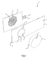
- Fig.1 shows an oblique view of an exploded view of components of an operating device 1, namely a plate 2 with a user interface 3 and a back 4, wherein on the user interface 3, a knob 5 is removably attached.
- the operating device 1 furthermore has an area sensor 6 arranged on the rear side 4.
- the plate 2 is of rectangular basic shape and manufactured in one piece by means of an injection molding process. While the back 4 is formed flat, the user interface 3 has a user guide element in the form of a raised, d. h., One from the user interface 3 projecting ring 8 on. An operator using the operating device 1 can activate a corresponding switching zone 12 of the surface sensor 6 by repositioning the ring 8 on its outer surface 9, inner surface 10 or upper edge 11 by means of a finger, pin or the like, as will be described in more detail below.
- the rotary knob 5 is placed on the ring 8, which on its side facing the user surface back 13 has a metallic projection 14 (bump), which produces a close approach or a contact surface with the user interface. On its front side, the rotary knob 5 for better operator guidance a survey 7.
- the area sensor 6 is a resistive sensor based on indium tin oxide (ITO) and has a plurality of closely spaced sensor points (not shown) arranged in a matrix form. In practice, it is fastened flat on the rear side 4 of the plate 2.
- the set of activated by a contact of the plate 2 sensor points is also called cursor focus 16.
- the sensor points of the cursor focus' give their signals here via four electrical leads 15 to a, here indicated only by the arrow 17, control unit, which checks the activated sensor points (cursor focus) on a correlation with predetermined switching zones ("4-wire system" ).
- the control unit 17 is designed here as a microcontroller.
- the switching zones are sets of sensor points defined by a programming of the microcontroller 17, the activation of which triggers a certain switching function of the household appliance.
- the size, shape and type of Switching zones (as rotary dials, push buttons, etc.) and their linking to a specific switching function are freely programmable and thus flexibly adaptable to the household appliance and an associated user interface.
- the type of switching zone and the connection of the switching zone with the switching function can be changed within an operator prompt, resulting in a particularly compact and user-friendly control device 1.
- the cursor focus 16 is always on the knob 5 within the switching zone 12 and triggers the switching function there.
- the microcontroller 17 can to detect a change in the rotational position (position of the cursor focus' 16) and trigger a corresponding switching function, z. For example, raising a device parameter when rotated clockwise and lowering a device parameter when rotated counterclockwise.
- the switching zone can also be embodied in the form of an annular sector, so that the microcontroller 17 can determine a change in the rotational position by a transition of the cursor focus 16 from one sector to the next sector (not shown).
- Each sector may then have a predetermined function, e.g. B. set a predetermined parameter, or for example, only detect changes to the parameter adjustment.
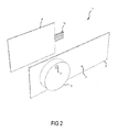
- Fig.2 shows that with attached knob 5, the ring 8 is no longer visible.
- the rotary knob 5 looks like that of a conventional rotary switch, which is perceived as familiar and reliable by some operators.
- 3A shows the unprinted user interface 4 of the plate 2, while 3B the plate 2 shows from below.
- the rectangular basic shape is rounded at the corners.
- the thickness d of the plate is 2 mm and the height h of the ring is 4 mm.
- the outer surface 9 and the inner surface 10 are rounded towards the user surface with a radius r3.
- On the back 13 a matching ring 8 recess in the form of an annular groove 18 is introduced into the knob 5.
- the knob 5 can thus by simply plugging onto the ring 8 so that the ring 8 engages pressingly into the groove 18, placed and removed by stripping again.
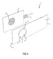
- FIG 4 shows the operating device 1 from Fig.1 with a differently programmed surface sensor 6, in which now the ring 8, a circular switching zone 26 is deposited, in the activation of a predetermined by the programming switching function is triggered.
- the ring 8 acts as a visible and haptic outer boundary of the switching zone 26.
- the switching zone 26 is not position sensitive and thus acts in their activation similar to a push button.
- the switching zone 26 can be used in the same household appliance as the switching zone 12 Fig.1 but, for example, in a different operating context, such as within another level of menu navigation.
- the switching zone 12,26 can be dynamically reprogrammed between a use for rotary voter-like operation and a use for the button-like operation, which allows a particularly flexible and compact operator guidance.
- the switching zone 12 may first be programmed for the rotary selector-like parameter setting of an operating mode of the household appliance and then reprogrammed as a button-like switching zone 26 to start the operating mode.
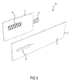
- FIG. 5 shows an operating device 19 according to a second embodiment, in which now the user guide element in the form of a horizontally disposed, linear recess 20 is present.
- the recess 20 has a curved surface contour transversely to the longitudinal direction L in order to simplify operation by means of a finger.
- a parameter adjustment can be easily adjusted by the recess, z.
- an operator increases a parameter as his finger slides to the right (or left) and decreases a parameter when sliding to the left (or right).
- the associated switching zone 25 corresponds to the control surface on the recess 20.
- the cursor focus on the surface sensor 6 corresponds approximately to the contact surface of the finger.
- Such an operator guide element 20 thus corresponds in its function to that of a linear slider.
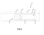
- Figure 6 shows in front view the position of components of a control panel 21 with an operating device 22 according to a third embodiment.
- the operating device 22 has a transparent PMMA plate 2 corresponding to those Fig.1 on, which is not deposited by a surface sensor 6, but by two ITO surface sensors 6.
- the optical design of the operating device 22, z. B. by single-color or multi-color display of texts, symbols, surfaces, etc., is behind the transparent surface sensors 6 each mounted a freely programmable monitor 23 spaced.
- the images displayed on the monitors 23 are projected through the transparent surface sensors 6 on the also plate 2 and are there readable by an operator. Due to the free programmability of the monitors, z. B. in the form of liquid crystal displays or LED displays, the optical identification can be changed very easily, for.
- the operating devices shown by way of example have the advantage that they are particularly easy to produce; Thus, they require a minimum of two elements, namely the plate and the surface sensor, wherein the plate is easy to produce in one piece.
- the operating device is flexibly configurable to manufacture by replacing the plate and reprogramming the surface sensor; As a result, differently shaped switching elements can be provided in a simple manner (pushbuttons, rotary switches, linear sliders, etc.).
- a particularly compact and user-friendly operating device can be achieved by dynamic reprogramming. In particular, by providing attachable controls a particularly high level of user-friendliness is achieved due to the flexible configuration option.
- the plate can also be made of glass, including glass ceramic, or even metal.
- Other operator guidance elements may also be incorporated in the plate, such as circular depressions.
- Other types of switches may be provided, such as a push-button type circuit, e.g. B. by pressing a circular recess.
- a switching function preferably triggered when a cursor focus has at least one common sensor point with the associated switching zone.
- multi-point circuits are possible in which several cursor foci are evaluated at the same time.
- a plate may have a plurality of user guide elements.
- the operating device can also have switching zones to which no user guidance elements are assigned.
- rotary actuations by means of a ring, knob, etc.
- the area sensor may be designed as a 5-wire or 8-wire system.
- a line sensor can also be used.
- the line sensor is an annular sensor with a plurality of sector-shaped switching zones, wherein the line sensor is arranged behind the ring 8 and has sufficient width for simple and error-free operation.
- the width can have, for example, an approximately width within the ring 8 which is about the width of a finger.
- a group of annularly arranged individual sensors each with a single switching zone, can also be used.
Landscapes
- Switches With Compound Operations (AREA)
- Electric Ovens (AREA)
- Electric Stoves And Ranges (AREA)
Applications Claiming Priority (1)
| Application Number | Priority Date | Filing Date | Title |
|---|---|---|---|
| DE102008043351A DE102008043351A1 (de) | 2008-10-31 | 2008-10-31 | Bedienvorrichtung für ein Hausgerät |
Publications (2)
| Publication Number | Publication Date |
|---|---|
| EP2182636A2 true EP2182636A2 (fr) | 2010-05-05 |
| EP2182636A3 EP2182636A3 (fr) | 2017-03-29 |
Family
ID=42026802
Family Applications (1)
| Application Number | Title | Priority Date | Filing Date |
|---|---|---|---|
| EP09174616.4A Withdrawn EP2182636A3 (fr) | 2008-10-31 | 2009-10-30 | Dispositif de commande d'un appareil ménager |
Country Status (2)
| Country | Link |
|---|---|
| EP (1) | EP2182636A3 (fr) |
| DE (1) | DE102008043351A1 (fr) |
Cited By (3)
| Publication number | Priority date | Publication date | Assignee | Title |
|---|---|---|---|---|
| EP2594850A1 (fr) * | 2011-11-18 | 2013-05-22 | BSH Bosch und Siemens Hausgeräte GmbH | Dispositif de commande pour un appareil ménager et appareil ménager doté dýun tel dispositif de commande |
| WO2020182654A3 (fr) * | 2019-03-11 | 2020-11-05 | BSH Hausgeräte GmbH | Dispositif de commande d'un appareil ménager comportant une zone de contact indiquée optiquement pour un élément de commande séparé, et appareil ménager |
| CN111916293A (zh) * | 2019-05-08 | 2020-11-10 | Bsh家用电器有限公司 | 用于对家用器具进行功能控制的操作设备 |
Families Citing this family (4)
| Publication number | Priority date | Publication date | Assignee | Title |
|---|---|---|---|---|
| DE102020124373A1 (de) | 2020-09-18 | 2022-03-24 | Diehl Ako Stiftung & Co. Kg | Drucktaste |
| DE102020215501A1 (de) * | 2020-12-08 | 2022-06-09 | BSH Hausgeräte GmbH | Bedienvorrichtung für ein Haushaltsgerät mit einem integrierten berührsensitiven Bedienring in einer Bedienmulde, sowie Haushaltsgerät |
| DE102022130189A1 (de) | 2022-11-15 | 2024-05-16 | Welbilt Deutschland GmbH | Küchen- und/oder gastronomiegerät |
| DE102024108589A1 (de) * | 2024-03-26 | 2025-10-02 | E.G.O. Elektro-Gerätebau GmbH | Bedieneinrichtung für ein Elektrogerät und Elektrogerät mit einer solchen Bedieneinrichtung |
Citations (3)
| Publication number | Priority date | Publication date | Assignee | Title |
|---|---|---|---|---|
| DE19917191A1 (de) | 1999-04-16 | 2000-10-26 | Preh Elektro Feinmechanik | Bedienelement zum Schalten und Steuern elektrisch bedienbarer Geräte mit einer Blende |
| WO2005019766A2 (fr) | 2003-08-21 | 2005-03-03 | Harald Philipp | Capteur de position capacitif |
| DE102004013947B3 (de) | 2004-03-22 | 2005-12-22 | Diehl Ako Stiftung & Co. Kg | Bedienvorrichtung für ein Glaskeramikkochfeld |
Family Cites Families (3)
| Publication number | Priority date | Publication date | Assignee | Title |
|---|---|---|---|---|
| DE10313401A1 (de) * | 2003-03-25 | 2004-10-07 | Zubler Gerätebau GmbH | Näherungssensitiver Drehschalter |
| DE102005002952A1 (de) * | 2005-01-21 | 2006-07-27 | BSH Bosch und Siemens Hausgeräte GmbH | Hausgeräteeinstelleinheit |
| DE102005033923A1 (de) * | 2005-07-20 | 2007-02-01 | Daimlerchrysler Ag | Bedienelement mit berührungsempfindlicher Bedienoberfläche |
-
2008
- 2008-10-31 DE DE102008043351A patent/DE102008043351A1/de not_active Ceased
-
2009
- 2009-10-30 EP EP09174616.4A patent/EP2182636A3/fr not_active Withdrawn
Patent Citations (3)
| Publication number | Priority date | Publication date | Assignee | Title |
|---|---|---|---|---|
| DE19917191A1 (de) | 1999-04-16 | 2000-10-26 | Preh Elektro Feinmechanik | Bedienelement zum Schalten und Steuern elektrisch bedienbarer Geräte mit einer Blende |
| WO2005019766A2 (fr) | 2003-08-21 | 2005-03-03 | Harald Philipp | Capteur de position capacitif |
| DE102004013947B3 (de) | 2004-03-22 | 2005-12-22 | Diehl Ako Stiftung & Co. Kg | Bedienvorrichtung für ein Glaskeramikkochfeld |
Cited By (6)
| Publication number | Priority date | Publication date | Assignee | Title |
|---|---|---|---|---|
| EP2594850A1 (fr) * | 2011-11-18 | 2013-05-22 | BSH Bosch und Siemens Hausgeräte GmbH | Dispositif de commande pour un appareil ménager et appareil ménager doté dýun tel dispositif de commande |
| WO2020182654A3 (fr) * | 2019-03-11 | 2020-11-05 | BSH Hausgeräte GmbH | Dispositif de commande d'un appareil ménager comportant une zone de contact indiquée optiquement pour un élément de commande séparé, et appareil ménager |
| CN113508263A (zh) * | 2019-03-11 | 2021-10-15 | Bsh家用电器有限公司 | 家用器具用的、具有光学显示的放置区(用于与之分开的操作元件)的操作设备和家用器具 |
| CN113508263B (zh) * | 2019-03-11 | 2023-12-15 | Bsh家用电器有限公司 | 家用器具用的、具有光学显示的放置区(用于与之分开的操作元件)的操作设备和家用器具 |
| CN111916293A (zh) * | 2019-05-08 | 2020-11-10 | Bsh家用电器有限公司 | 用于对家用器具进行功能控制的操作设备 |
| EP3736674A3 (fr) * | 2019-05-08 | 2020-12-02 | BSH Hausgeräte GmbH | Dispositif de commande destiné à la commande fonctionnelle des appareils électroménagers |
Also Published As
| Publication number | Publication date |
|---|---|
| EP2182636A3 (fr) | 2017-03-29 |
| DE102008043351A1 (de) | 2010-05-06 |
Similar Documents
| Publication | Publication Date | Title |
|---|---|---|
| EP2884187B2 (fr) | Procédé d'aide à l'utilisateur, composant d'écran, fabrication d'un composant d'écran et appareil ménager doté d'un composant d'écran | |
| DE10133135C5 (de) | Stelleinheit für Gargeräte | |
| EP1775650B1 (fr) | Dispositif de commande pour appareil électrique | |
| DE19645678C2 (de) | Bedieneinheit zum Schalten und Steuern von Haushaltsgeräten | |
| EP2687936B1 (fr) | Dispositif de commande à manette rotative | |
| EP2182636A2 (fr) | Dispositif de commande d'un appareil ménager | |
| EP2997659B1 (fr) | Élément d'actionnement | |
| DE102013021093B4 (de) | Bedienvorrichtung | |
| DE102013008702A1 (de) | Berührungs- und/oder annäherungsempfindliches Betätigungselement | |
| EP2652406B1 (fr) | Dispositif de commande pour appareil ménager doté d'un afficheur électronique et appareil ménager doté d'un dispositif de commande de ce type | |
| EP3221644B1 (fr) | Commande d'un appareil ménager au moyen d'un elément de commande détachable | |
| EP2715755A1 (fr) | Élément de commande pour commande de meuble et meuble électriquement réglable | |
| DE102005049995A1 (de) | Bedienvorrichtung für ein Elektrogerät und Bedienverfahren zur Bedienung eines Elektrogerätes | |
| EP2758716A1 (fr) | Appareil de cuisson à zone de commande sensitive | |
| DE102012210563A1 (de) | Betätigen eines Sensorbildschirms | |
| DE102007029193A1 (de) | Bedienvorrichtung | |
| DE202004021345U1 (de) | Berührungs-sensitives Bedienfeld | |
| DE102014113877A1 (de) | Drehwahlvorrichtung und Bedienvorrichtung für ein Haushaltsgerät, Verfahren zum Erfassen einer Bedienung einer Bedienblende und Verfahren zum Herstellen einer Bedienvorrichtung | |
| EP1876515B1 (fr) | Dispositif de commande | |
| DE102005063070B4 (de) | Vorrichtung zum Steuern eines Betriebsparameters eines elektrischen Geräts | |
| WO2008067998A2 (fr) | Dispositif de commande pour un appareil électrique comportant des interrupteurs tactiles et procédé de mise en circuit d'un appareil de chauffage supplémentaire | |
| DE202013004775U1 (de) | Berührungs- und/oder annäherungsempfindliches Betätigungselement | |
| DE102024136385A1 (de) | Bedienvorrichtung für ein Elektrokochgerät, Elektrokochgerät mit einer solchen Bedienvorrichtung und Verfahren zum Bedienen eines Elektrokochgeräts | |
| EP3200349A1 (fr) | Interface utilisateur capacitive |
Legal Events
| Date | Code | Title | Description |
|---|---|---|---|
| PUAI | Public reference made under article 153(3) epc to a published international application that has entered the european phase |
Free format text: ORIGINAL CODE: 0009012 |
|
| AK | Designated contracting states |
Kind code of ref document: A2 Designated state(s): AT BE BG CH CY CZ DE DK EE ES FI FR GB GR HR HU IE IS IT LI LT LU LV MC MK MT NL NO PL PT RO SE SI SK SM TR |
|
| AX | Request for extension of the european patent |
Extension state: AL BA RS |
|
| RAP1 | Party data changed (applicant data changed or rights of an application transferred) |
Owner name: BSH HAUSGERAETE GMBH |
|
| RIC1 | Information provided on ipc code assigned before grant |
Ipc: H03K 17/96 20060101AFI20161024BHEP |
|
| RIC1 | Information provided on ipc code assigned before grant |
Ipc: H03K 17/96 20060101AFI20161117BHEP |
|
| PUAL | Search report despatched |
Free format text: ORIGINAL CODE: 0009013 |
|
| AK | Designated contracting states |
Kind code of ref document: A3 Designated state(s): AT BE BG CH CY CZ DE DK EE ES FI FR GB GR HR HU IE IS IT LI LT LU LV MC MK MT NL NO PL PT RO SE SI SK SM TR |
|
| AX | Request for extension of the european patent |
Extension state: AL BA RS |
|
| RIC1 | Information provided on ipc code assigned before grant |
Ipc: H03K 17/96 20060101AFI20170220BHEP |
|
| STAA | Information on the status of an ep patent application or granted ep patent |
Free format text: STATUS: THE APPLICATION IS DEEMED TO BE WITHDRAWN |
|
| 18D | Application deemed to be withdrawn |
Effective date: 20170930 |