EP2884187B2 - Procédé d'aide à l'utilisateur, composant d'écran, fabrication d'un composant d'écran et appareil ménager doté d'un composant d'écran - Google Patents
Procédé d'aide à l'utilisateur, composant d'écran, fabrication d'un composant d'écran et appareil ménager doté d'un composant d'écran Download PDFInfo
- Publication number
- EP2884187B2 EP2884187B2 EP14196990.7A EP14196990A EP2884187B2 EP 2884187 B2 EP2884187 B2 EP 2884187B2 EP 14196990 A EP14196990 A EP 14196990A EP 2884187 B2 EP2884187 B2 EP 2884187B2
- Authority
- EP
- European Patent Office
- Prior art keywords
- operator
- sensor layer
- operating
- discrete
- layer
- Prior art date
- Legal status (The legal status is an assumption and is not a legal conclusion. Google has not performed a legal analysis and makes no representation as to the accuracy of the status listed.)
- Active
Links
Images


Classifications
-
- G—PHYSICS
- G06—COMPUTING OR CALCULATING; COUNTING
- G06F—ELECTRIC DIGITAL DATA PROCESSING
- G06F3/00—Input arrangements for transferring data to be processed into a form capable of being handled by the computer; Output arrangements for transferring data from processing unit to output unit, e.g. interface arrangements
- G06F3/01—Input arrangements or combined input and output arrangements for interaction between user and computer
- G06F3/03—Arrangements for converting the position or the displacement of a member into a coded form
- G06F3/041—Digitisers, e.g. for touch screens or touch pads, characterised by the transducing means
- G06F3/044—Digitisers, e.g. for touch screens or touch pads, characterised by the transducing means by capacitive means
- G06F3/0443—Digitisers, e.g. for touch screens or touch pads, characterised by the transducing means by capacitive means using a single layer of sensing electrodes
-
- A—HUMAN NECESSITIES
- A47—FURNITURE; DOMESTIC ARTICLES OR APPLIANCES; COFFEE MILLS; SPICE MILLS; SUCTION CLEANERS IN GENERAL
- A47L—DOMESTIC WASHING OR CLEANING; SUCTION CLEANERS IN GENERAL
- A47L15/00—Washing or rinsing machines for crockery or tableware
- A47L15/42—Details
-
- D—TEXTILES; PAPER
- D06—TREATMENT OF TEXTILES OR THE LIKE; LAUNDERING; FLEXIBLE MATERIALS NOT OTHERWISE PROVIDED FOR
- D06F—LAUNDERING, DRYING, IRONING, PRESSING OR FOLDING TEXTILE ARTICLES
- D06F34/00—Details of control systems for washing machines, washer-dryers or laundry dryers
- D06F34/28—Arrangements for program selection, e.g. control panels therefor; Arrangements for indicating program parameters, e.g. the selected program or its progress
- D06F34/32—Arrangements for program selection, e.g. control panels therefor; Arrangements for indicating program parameters, e.g. the selected program or its progress characterised by graphical features, e.g. touchscreens
-
- F—MECHANICAL ENGINEERING; LIGHTING; HEATING; WEAPONS; BLASTING
- F24—HEATING; RANGES; VENTILATING
- F24C—DOMESTIC STOVES OR RANGES ; DETAILS OF DOMESTIC STOVES OR RANGES, OF GENERAL APPLICATION
- F24C7/00—Stoves or ranges heated by electric energy
- F24C7/08—Arrangement or mounting of control or safety devices
- F24C7/082—Arrangement or mounting of control or safety devices on ranges, e.g. control panels, illumination
- F24C7/086—Arrangement or mounting of control or safety devices on ranges, e.g. control panels, illumination touch control
-
- G—PHYSICS
- G06—COMPUTING OR CALCULATING; COUNTING
- G06F—ELECTRIC DIGITAL DATA PROCESSING
- G06F3/00—Input arrangements for transferring data to be processed into a form capable of being handled by the computer; Output arrangements for transferring data from processing unit to output unit, e.g. interface arrangements
- G06F3/01—Input arrangements or combined input and output arrangements for interaction between user and computer
- G06F3/016—Input arrangements with force or tactile feedback as computer generated output to the user
-
- G—PHYSICS
- G06—COMPUTING OR CALCULATING; COUNTING
- G06F—ELECTRIC DIGITAL DATA PROCESSING
- G06F3/00—Input arrangements for transferring data to be processed into a form capable of being handled by the computer; Output arrangements for transferring data from processing unit to output unit, e.g. interface arrangements
- G06F3/01—Input arrangements or combined input and output arrangements for interaction between user and computer
- G06F3/048—Interaction techniques based on graphical user interfaces [GUI]
- G06F3/0487—Interaction techniques based on graphical user interfaces [GUI] using specific features provided by the input device, e.g. functions controlled by the rotation of a mouse with dual sensing arrangements, or of the nature of the input device, e.g. tap gestures based on pressure sensed by a digitiser
- G06F3/0488—Interaction techniques based on graphical user interfaces [GUI] using specific features provided by the input device, e.g. functions controlled by the rotation of a mouse with dual sensing arrangements, or of the nature of the input device, e.g. tap gestures based on pressure sensed by a digitiser using a touch-screen or digitiser, e.g. input of commands through traced gestures
- G06F3/04883—Interaction techniques based on graphical user interfaces [GUI] using specific features provided by the input device, e.g. functions controlled by the rotation of a mouse with dual sensing arrangements, or of the nature of the input device, e.g. tap gestures based on pressure sensed by a digitiser using a touch-screen or digitiser, e.g. input of commands through traced gestures for inputting data by handwriting, e.g. gesture or text
-
- H—ELECTRICITY
- H03—ELECTRONIC CIRCUITRY
- H03K—PULSE TECHNIQUE
- H03K17/00—Electronic switching or gating, i.e. not by contact-making and –breaking
- H03K17/94—Electronic switching or gating, i.e. not by contact-making and –breaking characterised by the way in which the control signals are generated
- H03K17/96—Touch switches
-
- H—ELECTRICITY
- H03—ELECTRONIC CIRCUITRY
- H03K—PULSE TECHNIQUE
- H03K17/00—Electronic switching or gating, i.e. not by contact-making and –breaking
- H03K17/94—Electronic switching or gating, i.e. not by contact-making and –breaking characterised by the way in which the control signals are generated
- H03K17/96—Touch switches
- H03K17/962—Capacitive touch switches
- H03K17/9622—Capacitive touch switches using a plurality of detectors, e.g. keyboard
-
- D—TEXTILES; PAPER
- D06—TREATMENT OF TEXTILES OR THE LIKE; LAUNDERING; FLEXIBLE MATERIALS NOT OTHERWISE PROVIDED FOR
- D06F—LAUNDERING, DRYING, IRONING, PRESSING OR FOLDING TEXTILE ARTICLES
- D06F2101/00—User input for the control of domestic laundry washing machines, washer-dryers or laundry dryers
- D06F2101/12—Washing temperature
-
- D—TEXTILES; PAPER
- D06—TREATMENT OF TEXTILES OR THE LIKE; LAUNDERING; FLEXIBLE MATERIALS NOT OTHERWISE PROVIDED FOR
- D06F—LAUNDERING, DRYING, IRONING, PRESSING OR FOLDING TEXTILE ARTICLES
- D06F2101/00—User input for the control of domestic laundry washing machines, washer-dryers or laundry dryers
- D06F2101/14—Time settings
-
- D—TEXTILES; PAPER
- D06—TREATMENT OF TEXTILES OR THE LIKE; LAUNDERING; FLEXIBLE MATERIALS NOT OTHERWISE PROVIDED FOR
- D06F—LAUNDERING, DRYING, IRONING, PRESSING OR FOLDING TEXTILE ARTICLES
- D06F2105/00—Systems or parameters controlled or affected by the control systems of washing machines, washer-dryers or laundry dryers
- D06F2105/58—Indications or alarms to the control system or to the user
-
- G—PHYSICS
- G06—COMPUTING OR CALCULATING; COUNTING
- G06F—ELECTRIC DIGITAL DATA PROCESSING
- G06F2203/00—Indexing scheme relating to G06F3/00 - G06F3/048
- G06F2203/041—Indexing scheme relating to G06F3/041 - G06F3/045
- G06F2203/04103—Manufacturing, i.e. details related to manufacturing processes specially suited for touch sensitive devices
-
- G—PHYSICS
- G06—COMPUTING OR CALCULATING; COUNTING
- G06F—ELECTRIC DIGITAL DATA PROCESSING
- G06F2203/00—Indexing scheme relating to G06F3/00 - G06F3/048
- G06F2203/048—Indexing scheme relating to G06F3/048
- G06F2203/04808—Several contacts: gestures triggering a specific function, e.g. scrolling, zooming, right-click, when the user establishes several contacts with the surface simultaneously; e.g. using several fingers or a combination of fingers and pen
-
- H—ELECTRICITY
- H03—ELECTRONIC CIRCUITRY
- H03K—PULSE TECHNIQUE
- H03K2217/00—Indexing scheme related to electronic switching or gating, i.e. not by contact-making or -breaking covered by H03K17/00
- H03K2217/94—Indexing scheme related to electronic switching or gating, i.e. not by contact-making or -breaking covered by H03K17/00 characterised by the way in which the control signal is generated
- H03K2217/96—Touch switches
- H03K2217/96066—Thumbwheel, potentiometer, scrollbar or slider simulation by touch switch
-
- H—ELECTRICITY
- H03—ELECTRONIC CIRCUITRY
- H03K—PULSE TECHNIQUE
- H03K2217/00—Indexing scheme related to electronic switching or gating, i.e. not by contact-making or -breaking covered by H03K17/00
- H03K2217/94—Indexing scheme related to electronic switching or gating, i.e. not by contact-making or -breaking covered by H03K17/00 characterised by the way in which the control signal is generated
- H03K2217/96—Touch switches
- H03K2217/9607—Capacitive touch switches
- H03K2217/960755—Constructional details of capacitive touch and proximity switches
-
- Y—GENERAL TAGGING OF NEW TECHNOLOGICAL DEVELOPMENTS; GENERAL TAGGING OF CROSS-SECTIONAL TECHNOLOGIES SPANNING OVER SEVERAL SECTIONS OF THE IPC; TECHNICAL SUBJECTS COVERED BY FORMER USPC CROSS-REFERENCE ART COLLECTIONS [XRACs] AND DIGESTS
- Y10—TECHNICAL SUBJECTS COVERED BY FORMER USPC
- Y10T—TECHNICAL SUBJECTS COVERED BY FORMER US CLASSIFICATION
- Y10T29/00—Metal working
- Y10T29/49—Method of mechanical manufacture
- Y10T29/49002—Electrical device making
Definitions
- the invention relates to a method for selective user guidance for user inputs in a household appliance.
- the invention also relates to a panel component for a control panel of a household appliance, a control arrangement with a panel component, and a method for producing a panel component for a control panel of a household appliance.
- Various aspects of the disclosure also deal with user guidance for operator inputs in household appliances.
- Household appliances can in particular be so-called "white goods", i.e. conventional appliances for cooling, washing, cooking, baking and the like.
- a method for controlling and/or evaluating an elongated sensor element of a touch switch of an operating device for an electrical device is known, with touching or placing a finger above the sensor element being detected and evaluated, with a first operating mode being essentially stationary or not lateral moving finger placement is evaluated as a point-like actuation with an operating signal assigned to the location of the actuation, and wherein in a second operating mode actuation or placing of a finger with a placed and pulling movement along the longitudinal direction of the sensor element depending on the length and/or or the start and end point of the actuation is evaluated as a pulling, elongated actuation with another operating signal assigned to the longitudinal area and/or the length of the actuation.
- a touch switch for an electrical device which has an LC display.
- the EP 1 273 851 A2 shows a control unit for cooking appliances, with a touch-sensitive control strip, the control sections of which are assigned or optionally assignable to setting values or setting value ranges of a predetermined setting curve.
- the DE 10 2005 032 088 A1 shows a cooking appliance with an operating arrangement with at least one touch-sensitive control strip for setting a control variable in a first operating mode depending on a touch position on the control strip, the operating arrangement having at least one selector switch for switching from the first operating mode to at least one second operating mode.
- a control panel arrangement for a household appliance which has a circuit arrangement with three or more separate electrodes, with an evaluation unit being provided which determines the spatial position of an operator's finger by means of triangulation.
- a household appliance with a touch-sensitive operating and display device which has a display unit for displaying operating information and a transparent carrier part on which a capacitive sensor electrode is arranged as part of a touch capacitor, the sensor electrode being made of a transparent and electrically conductive paint or adhesive is.
- Panel arrangements or control panels in household appliances can usually have interfaces for user interaction. This can be, for example, displays, indicator lights, rotary switches, push buttons, push buttons, touch-sensitive surfaces or displays as well as associated labels or symbols.
- Conventional input elements such as buttons or switches often lead to a certain amount of effort in the production of control panels and panel arrangements. This effort is all the higher, the more options are provided for user interaction, so the more user inputs are possible. Furthermore, a significant increase in the number of switches, buttons or the like can make it more difficult to operate the household appliance.
- the DE 10 2008 032 451 A1 a cooking appliance and a method for operating a cooking appliance, the cooking appliance having an input display which is designed as a touchscreen and can display various information graphically.
- information is presented in the form of graphic visualizations and/or animations.
- such a design is associated with a great deal of effort and is therefore primarily only suitable for high-end devices and devices for professional use.
- a program-controlled household appliance with an operating and display device which has a touch-sensitive display surface in the form of a touchscreen, in which programs and program parameters can be displayed and can be selected and/or changed by a user touching corresponding operating and display fields.
- the display area has a control and display bar extending across its width, a control and display field extending below the status bar, and a control and display bar extending below the work area.
- the screen component should be suitable for a large number of variants and configurations, in order to be able to limit the production costs even with relatively small batch sizes.
- user guidance should be ensured that facilitates the operation and use of the household appliance.
- the panel arrangement and the household appliance with such a panel arrangement should have a high-quality, integrated design and should therefore be perceived as visually high-quality by the operator.
- the object of the invention is achieved by a method for selective user guidance for user inputs in a household appliance according to claim 1.
- the object of the invention is achieved by a panel component for a control panel for a household appliance according to claim 4.
- the object of the invention is achieved by a method for manufacturing a panel component of a control panel for a household appliance according to claim 13.
- the object of the invention is also completely achieved in this way.
- the sensor layer can be arranged “invisibly” for an operator behind the cover layer, with the sensor layer defining an area, in particular an area, in which operator inputs can potentially be recorded.
- a section of the sensor layer can now be deliberately selected and activated in order to be able to record and evaluate user inputs there.
- the panel component can have a basic configuration and can be controlled in a variant-specific manner depending on the desired configuration. For example, it is conceivable to actually use only one or more (area) sections of the sensor layer in the selected variant for recording and evaluating the operator inputs. In this way, a large number of variants can be made possible for the screen component with little effort.
- the activation or assignment of the sensor layer or the selected sections of the sensor layer can take place during operation depending on the currently desired input mode.
- one and the same sensor layer or sections thereof can be selected for different inputs.
- a certain selected section of the sensor layer can be used both to select a washing program (first input mode) and to select a washing temperature (second input mode).
- the sensor layer is arranged on the side of the cover layer of the panel component that faces away from the operator in the installed state. Accordingly, it does not lead to optical impairments if only a section of the sensor layer is actually used to record and evaluate operator inputs.
- the bezel component is provided with a display layer (or: display plane) which is arranged behind the sensor layer (viewed from the cover layer).
- the display layer and the sensor layer are arranged one above the other at least in sections.
- the display layer is formed from at least one discrete display element.
- a discrete display element can be, in particular, an optical display element that is designed to display a limited amount of information.
- the display element is not a graphic display that is designed to display images generated from pixels.
- a discrete display element within the meaning of the present disclosure is status symbols, control displays, control LEDs, bar displays, segment displays and similar “discrete” display elements. Discrete display elements are usually significantly cheaper than pixel-based graphic display elements.
- discrete display elements regularly have a higher level of robustness and suitability for fluctuating environmental conditions.
- a large amount of information can be displayed even without a pixel-based display.
- the operator can be given the feeling of acting directly on the display, since he can make inputs directly in the area of the activated or activatable discrete display elements.
- At least one discrete display element preferably a plurality of discrete display elements, defining the display layer may be placed "behind" the sensor layer.
- the at least one discrete display element can be used in connection with the ability to allocate and activate sections of the sensor layer for selective user guidance or user instructions.
- at least one discrete display element can be selectively activated in order to output an optical signal that shows the operator that he can make entries in the area of the activated display element that are detected by the (covered) sensor layer.
- the panel component in particular its sensor layer, is preferably designed to record analog or quasi-analog inputs from the operator.
- the sensor layer is not only used to switch specific functions (digitally) on or off. Rather, it is made possible to record extended user inputs, in particular user gestures, which, for example, allow a value to be selected within a value range.
- extended user inputs in particular user gestures, which, for example, allow a value to be selected within a value range.
- the operation of the household appliance can be significantly simplified.
- the operator can select a target temperature within a relatively wide temperature range by simply "swiping" along the cover sheet.
- the operator can also, in another operating mode, make a program selection in the same area, for example, if this is indicated to him by a corresponding activated discrete display element.
- Operator inputs may generally include approaching the cover sheet and/or touching the cover sheet. Operator inputs can also be selective (e.g. in the sense of a click or a double click). However, operator input may also include motion paths, such as swipe motions, circular motions, or the like. In principle, operator inputs can be made with a tool, such as a pen, or with body parts, in particular with fingers or thumbs. Operator inputs can also be combined to enable complex functions. This can be, for example, a zoom function, ie an enlargement or reduction function. Such complex gestures can be used, for example, to influence the sensitivity of the sensor layer to certain operator inputs. Other advanced/complex inputs are conceivable. For example, the sensitivity for swiping gestures, for example for temperature selection or time selection, can be influenced by means of a zoom gesture.
- operator prompting can include instructions or instructions for input to the operator, but also feedback to the operator after the input has been made.
- Guidance may be provided, for example, when an activated discrete indicator designates or highlights a specific area of the (hidden) sensor layer that is currently activated to detect operator gestures.
- Feedback to the operator can include, for example, a specific visual output that is used to react to a specific operator input. This can include, for example, changing a bar display that is designed as a discrete display element. Further, the visual output may include, for example, a color change of a discrete display element. In this way, complex information can be displayed with display elements that are relatively simple in design. A sufficiently detailed user interaction can take place, this can increase the value perceived by the operator.
- the covering layer of the screen component completely covers the sensor layer.
- the cover layer is in particular a substantially closed cover layer that completely covers the sensor layer.
- the sensor layer is preferably arranged on the rear side of the cover layer, that is to say on the side of the cover layer which faces away from the operator during normal operation.
- the manufacturing process for producing the screen component allows great flexibility in production. Since a large potentially activatable sensor surface can be provided by means of the sensor layer that can be activated in sections, sections for user inputs can be specifically selected from this by suitable contacting or activation (in each case according to the currently desired configuration).
- the introduction of the sensor layer, which can be activated in sections does not involve any significant additional effort. Rather, there can be cost advantages in production, since a large number of variants can be implemented on the basis of a basic configuration. The variants can differ from each other, for example, in terms of the variety of functions. Irrespective of whether the household appliance to be manufactured has a low, medium or even high range of functions, the required operator inputs can be recorded and evaluated in a simple manner by configuring and controlling the activatable sensor layer.
- the screen component can be provided with the sensor layer in the manner mentioned and printed on its side facing the operator or treated in some other way in order to generate operating symbols perceptible to the operator.
- a corresponding layout of the sensor layer can now be selected for selective activation in terms of software or control technology.
- a control device can be configured and designed in such a way that operator inputs are only detected in the areas of the sensor layer that correspond to the operator symbols generated on the cover layer.
- the corresponding assignment of the selected sections of the sensor layer can be implemented in a simple manner using software or circuitry.
- a freely scalable control panel can be created. The control panel can receive its functional assignment at the end of the production process.
- the interface can be, for example, contacting the sensor layer, via which the control device communicates with the sensor layer. Furthermore, the interface can include contacting the control device with the at least one discrete display element, so that the control device can selectively activate or deactivate the at least one discrete display element.
- the operator guidance can take place by means of elements that can be activated selectively, the at least one discrete display element, and with permanently present elements, the at least one optically and/or haptically perceptible operating symbol. Both types of elements can be combined with one another in an advantageous manner.
- the sensor layer is designed as a capacitive sensor layer, with the sensor layer being designed in particular to detect touches on the cover layer and/or approaches to the cover layer in the area of the sensor layer.
- the sensor layer can be configured as a projected-capacitive sensor layer.
- the sensor layer can be designed in particular as a film-based sensor layer. It goes without saying that other functional principles for the sensor layer can be used to detect touches and/or proximity to the cover layer.
- the sensor layer can be designed as an inductive sensor layer, a resistive sensor layer, as an optical sensor layer and/or as a combined sensor layer.
- the sensor layer can, in particular, comprise two planes which are insulated from one another and are each provided with conductive material.
- a first level can have a row structure and a second level can have a column structure.
- Other designs such as diamonds or the like are conceivable.
- the sensor layer is designed to record multi-dimensional operator gestures and/or multiple operator inputs at the same time.
- multidimensional operator gestures may include swiping.
- the ability to capture multiple operator inputs simultaneously may be referred to as multi-touch capability.
- the panel component includes an interface for a control device which is designed to the sensor layer and the at least selectively drive a discrete display element to define a plurality of input modes.
- the at least one discrete indicator element can be selectively activated to indicate to an operator that a certain type of input can be made at a certain location of the sensor layer.
- the control device can specifically activate a section of the sensor layer for inputs and evaluate it accordingly.
- the control device is designed to define a current input mode, the control device also being designed to assign at least one field to be evaluated for operator inputs on the sensor layer, taking into account at least one selected input mode. This can advantageously be accompanied by the activation of at least one discrete display element in order to indicate to the operator where he can make his inputs and what type of input is currently required.
- a system for detecting operator inputs that includes at least one screen component and at least one control device according to one of the aforementioned aspects.
- Such a system can be formed on the one hand as a discrete component.
- the display layer comprises at least one display element which is designed as a discrete, selectively activatable symbol or as a discrete, selectively activatable segment display, in particular as a seven-segment display.
- a selectively activatable symbol can be a light-emitting diode or a collection of light-emitting diodes.
- the symbol that can be activated selectively can also include a symbol representation, for example a silhouette or a pictogram that can be illuminated by means of an LED or a similar light source.
- a segment display that can be activated selectively can include a bar display, a circular segment display, a multi-segment display for displaying alphanumeric information, or the like.
- the at least one display element can be adapted in particular to an expected user input.
- a wipe function can be combined with a bar segment display and/or an alphanumeric segment display.
- the cover layer and the sensor layer are designed to be transparent or translucent at least in sections.
- the cover layer and the sensor layer can be optically transparent at least in sections and thus improve the optical perception of the at least one discrete display element, which can be covered both by the sensor layer and by the cover layer.
- the cover layer and the sensor layer can be at least partially transparent or translucent, so that when a discrete display element is not activated, it cannot be perceived by the operator. In this way, the operation of the household appliance can be further simplified since discrete display elements that are not currently required can be made "invisible".
- the covering layer is surface-treated at least in sections, in particular printed or coated, the covering layer having at least one optically and/or haptically perceptible operating symbol for operator guidance.
- the cover layer can be printed.
- the cover layer can be provided with raised or recessed design elements. It is also conceivable to specifically influence the surface quality of the cover layer in order to clearly emphasize the at least one operating symbol.
- the measures mentioned can be combined with one another.
- the panel component can be provided with permanently visible elements as an alternative or in addition to the selectively activatable, discrete display elements in order to identify input options for the operator.
- the at least one optically and/or haptically perceptible operating symbol can include a graphic representation and/or an alphanumeric representation. In particular, the use of pictograms is conceivable.
- a corresponding field or a section in the sensor layer can be assigned to the at least one operating symbol of the covering layer, in which user inputs which are linked to the operating symbol can be recorded.
- a panel component according to one of the aforementioned aspects is used in a household appliance.
- the defined field to be evaluated is at least adjacent to the activated discrete display element.
- the assigned field to be evaluated (from the operator's point of view) is in front of the activated discrete display element. In this way, the operator can get the impression that he can make the desired inputs directly on the display element, for example a selection or a change in a value.
- the step of defining the current input mode also includes the step of assigning the field to be evaluated for user inputs to an operating symbol that is optically and/or haptically perceptible on the cover layer.
- permanently perceptible symbols can also be used to instruct and guide the operator.
- permanently visible elements and selectively activatable elements can be combined with one another in order to further increase user comfort and reduce the risk of operating errors.
- the discrete display element activated for the purpose of feedback to the operator is located in the currently assigned field or at least in the vicinity of the currently assigned field from the operator's point of view, so that the impression of direct feedback is given. This can further increase the perceived value of the household appliance and the operating process.
- the object is achieved by an operating arrangement for a household appliance with a panel component according to one embodiment of the present disclosure, the operating arrangement comprising a plurality of defined operating areas which are formed in particular on the panel component, and wherein each operating area has at least one field for Operator input and at least one display element is assigned.
- an integrally designed operating arrangement can result, which enables expanded functionality.
- the panel component is designed as an integral panel component into which the operating areas are integrated, with at least a first operating area and a second operating area being provided, with the first operating area comprising a setting controller that can be controlled by means of gestures and display elements for visually highlighting a setting area, and wherein the second operating area comprises a multifunctional display with at least one display element, which is designed at least to display a value selected in the first operating area. Fields on one and the same sensor layer can be assigned to the first operating area and the second operating area.
- the display elements of the first operating area are designed to carry out a color change or a color gradient change in response to an operator input.
- LEDs with different colors and/or different filters can be combined and selectively controlled.
- the second operating area is also designed to record user inputs, in particular user gestures, and to display information in response to the user inputs. Operator gestures may include tapping or swiping input.
- a third operating area is also integrated into the panel component, with the third operating area preferably being designed as an operating area for quick selection inputs. At least one corresponding field can also be assigned to the third operating area on one and the same sensor layer.
- At least one of the operating areas is haptically emphasized, with a haptically perceptible emphasis being formed in particular on the covering layer. This can further improve user guidance and allow intuitive operation.
- the haptic emphasis does not regularly result in additional effort in the design of the sensor layer.
- the haptic highlighting comprises a depression and/or an elevation in the marked operating area. This can preferably be done at the cover layer.
- the haptic highlighting is designed as a circular ring-like highlighting or as a circular ring segment-like highlighting and assigned to a control area designed as a setting controller. In this way, setting inputs and selection inputs can be made more easily. Gesture controls through fingertip touches can be simplified due to the "guidance" of the fingers by haptic emphasis.
- At least one display element which is assigned to an operating area, can be operated in different operating modes, in particular in an inactive mode, an activatable mode and an activated one Mode.
- the at least one display element is deactivated in the inactive mode.
- the at least one display element In the mode that can be activated, the at least one display element can have a reduced brightness.
- the activated mode the at least one display element can have a high level of brightness.
- the operating modes can also be characterized by defined color assignments.
- the inactive mode can be understood as a state of the display element in which the field assigned to it cannot be used for operator inputs. This may include an associated feature not being available.
- the activatable mode can be understood as a state of the display element in which the field assigned to it is at least potentially available for operator inputs.
- the activated mode can be understood as a state of the display element in which the field assigned to it has actually been selected by the operator. The selection made can be displayed to the operator in this way.
- An operating arrangement is used in a household appliance.
- FIG. 1 shows a perspective view of a household appliance 10 which has a panel arrangement or control panel 12 .
- the household appliance 10 can be a dishwasher or the like.
- Household appliances 10 can, for example, also be designed as washing machines, refrigerators, freezers, ovens, stoves, microwaves, tumble dryers or the like. Household appliances that combine different functions, such as fridge-freezers, are also conceivable.
- control panel 12 has at least one panel component 14 .
- the at least one screen component 14 can include areas in which elements for operation or for user interaction are arranged. It goes without saying that the control panel 12 can in particular be designed essentially in one piece.
- the panel component(s) 14 can be integral parts of the control panel 12 . However, it is also conceivable to design a plurality of panel components 14 as individual parts and to add them to the control panel 12 .
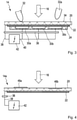
- FIG. 2 shows a greatly simplified schematic perspective exploded view of an exemplary embodiment of a panel component 14.
- An arrow labeled 16 indicates a typical viewing direction of an operator who can make operating inputs on the panel component 14.
- the panel component 14 On its side facing the operator, the panel component 14 has a cover layer 20, which can be designed in particular as a plastic component.
- a sensor layer 22 is arranged “behind” or “beneath” the covering layer 20 from the perspective of the operator.
- the sensor layer 22 can be used as a sensor layer 22 for detecting Touches or approaches may be formed. It is understood that the sensor layer 22 in the basis of 2 Illustrated embodiment can be designed to detect touches or approaches on the level of the cover layer 20, which can cover the sensor layer 22, in particular can completely cover it.
- the sensor layer 22 can in particular be designed as a touch-sensitive conductive film, at least in sections.
- a so-called display layer 24 can be connected to the rear of the sensor layer 22, ie on the side of the panel component 14 facing away from the operator during normal operation. This can be designed, for example, to visually highlight certain areas of the sensor layer 22 for the operator for the purpose of operator guidance and interaction.
- the covering layer 20 can be provided at least partially with transparent or translucent areas 26 .
- the sensor layer 22 can also be designed to be translucent or transparent, at least in sections.
- This sensor layer 22 can include a sensor network 28 and can be designed, for example, as a film component that has various conductive areas.
- the sensor layer 22 can be designed as a transparent film, but alternatively also as a substantially non-transparent or opaque film. It goes without saying that the sensor layer 22 can comprise a layer structure, for example different conductive layers insulated from one another.
- the sensor layer 22 can generally define an area in which operator inputs (contacts or approaches) in the area of the cover layer 20 can be detected and evaluated.
- the display layer (also: display level) 24 can comprise at least one discrete display element 30 .
- the 2 Illustrated display layer 24 includes a first discrete display element 30a and a second discrete display element 30b.
- the display layer 24 need not be provided as a physical part. Rather, the display layer 24 can be understood, at least in some configurations, as a (logical) combination of various discrete display elements 30 . It goes without saying, however, that in alternative configurations the display layer 24 can, for example, function as a carrier structure for the at least one discrete display element 30 .
- the at least one discrete display element 30 can be designed, for example, as a pictogram, symbol, (predefined) alphanumeric display, segment display, segmented bar display or in a similar way.
- the at least one discrete display element 30 should in particular not be understood as a pixel-based graphic display element. Rather, it is preferred if the at least one discrete display element is predefined and designed in such a way as to display precisely one item of graphical information or a limited number of different items of graphical information.
- the at least one discrete display element can in particular be illuminated in order to ensure sufficient visual emphasis for the operator. Light-emitting diodes, (discrete) LCD elements or the like are suitable for this purpose.
- a limited variation of the information that can be displayed by the at least one discrete display element 30 can be achieved, for example, by colored highlighting.
- the displayable information can be varied by controlling different segments/sub-elements.
- alphanumeric information can also be displayed, at least to a limited extent, by means of segment displays, with the number of digits or letters that can be displayed being predefined and limited.
- Screen components 14 make use of the fact that the sensor layer 22 can be applied to the cover layer 20 over a large area at a reasonable cost.
- Joining the covering layer 20 to the sensor layer 22 can include, for example, gluing, overmoulding, back-moulding, embedding, a non-positive and/or positive assembly and other common joining methods.
- the panel component 14 can be mass-produced in a basic configuration, for example comprising the covering layer 20 and the sensor layer 22, with reasonable effort.
- the panel component 14 is particularly suitable for selective packaging. This can include, for example, assigning sections or fields of the sensor layer 22 to detect certain operator inputs. In other words, a predefined basic configuration can be used by targeted control of the sensor layer with little effort for a large number of variations with regard to the permitted and offered scope of operation.
- FIG. 3 shows a panel component 14, which is approximately based on the substantially 2 illustrated panel member 14 may correspond.
- the aperture component 14 according to 3 has a cover layer 20, a sensor layer 22 and a display layer 24.
- the display layer 24 is provided with various discrete display elements 30a, 30b, 30c.
- the screen component 14 can be coupled to a control device 42 which can communicate with the sensor layer 22 and the display layer 24 via an interface 36 and corresponding connection lines 38 , 40 .
- the control device 42 is connected to the sensor layer 22 via the connecting line 38 .
- the control device 42 can use the connection line 38 to record information that describes, for example, touches or approaches to an outer surface 34 of the covering layer 20 .
- Operator inputs can be made by means of an actuator 32, 32a.
- the actuator 32, 32a can be be in particular a part of the operator's body, such as a finger. However, it is also conceivable to use an input pen (stylus) or the like.
- the sensor layer 22 and the control device 42 can be designed to detect touches of the cover layer 20, cf. the finger 32. Alternatively or additionally, the sensor layer 22 and the control device 42 can also be designed to detect approaches, i.e. no direct touches, to the Cover layer 20, see finger 32a.
- the control device 42 can also be coupled to the discrete display elements 30a, 30b, 30c via the connecting line 40.
- the discrete display elements 30a, 30b, 30c can be selectively controlled or activated in order to guide the operator or to guide the user with a desired operator input.
- the discrete display elements 30a, 30b, 30c can be used to visually highlight a subsection or field from the sensor layer 22 that is currently allocated and provided. In this way, the sensor layer 22 can be used for a variety of different inputs and is flexibly configurable in this regard.
- the discrete display elements 30a, 30b, 30c can also at least partially overlap in various alternative configurations.
- one and the same area of the cover layer 20 can be used for different inputs depending on the configuration of the sensor layer 22 .
- one and the same area in a washing machine can be used to select a program mode, to preselect the temperature and to control the time and for the associated user inputs or operator inputs that are required.
- the section actually used in each case or the respectively selected field of the sensor layer 22 does not have to be identical or congruent. Rather, by logically controlling the sensor layer 22, a large number of sections or fields can be defined and used to record and evaluate operator inputs.
- the fields can be defined and assigned, for example, using software and/or circuitry.
- the panel component 14a has a cover layer 20 and a sensor layer 22, which is arranged or applied on the side of the cover layer 20 facing away from the operator.
- the sensor layer 22 is designed to detect touches or approaches.
- the panel component 14a can be coupled to a control device 42 which can be connected to the sensor layer 22 via a connecting line 38 via an interface 36 .
- the covering layer 20 can also be provided with at least one operating symbol 46 .
- This is exemplified by the 4 Illustrated screen component 14 has a raised operating symbol 46a and a sunken operating symbol 46b on its covering layer 20.
- the operating symbols 46 can be provided on the cover layer 20 so that they can be perceived visually and/or haptically.
- the operating symbols 46 can be introduced into the covering layer 20 when it is being shaped, for example during injection molding. In principle, the operating symbols 46 can be highlighted in color.
- the sensor layer 22 can define a potentially possible area in which user inputs can be detected.
- the sensor layer 22 can now be controlled in such a way that certain sections or fields, ie subsets of the sensor layer 22, are specifically used and evaluated for certain user inputs.
- the fields defined in each case can in particular be adjacent to or assigned to the respective operating symbol 46a, 46b.
- a “semi-finished product” of the screen component 14a can be manufactured, for example, which has a basic configuration. Such a “semi-finished product” can then be used to form variants by specifically emphasizing various operating symbols 46 on it. This can be done, for example, by means of printing. A currently selected configuration of the operating symbols 46a, 46b can be linked to an associated logical activation of the sensor layer 22. A large number of variants can be implemented on the basis of just one basic configuration.
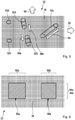
- FIG. 12 illustrates a schematic plan view of an exemplary sensor layer 22.
- the sensor layer 22 has a sensor network 28, which can have a structure comprising columns and rows.
- an arrow labeled 48 can illustrate a first direction
- an arrow labeled 50 can illustrate a second direction.
- the arrows 48, 50 can represent an X direction and a Y direction, for example.
- the sensor layer 22 is designed to detect operator inputs locally (ie in relation to the first direction 48 and the second direction 50). In the case of a capacitive sensor layer 22, for example, this can be done by influencing a capacitance as a result of touching or approaching, which is detected and evaluated.
- FIG. 5 Illustrated as an example figure 5 furthermore, various conceivable operator inputs or operator gestures that can be detected and evaluated.
- a single touch tip or click
- 52a 52b illustrates a chronologically consecutive double touch (a so-called double click).
- 52c is a gesture in the form of a sliding movement (a so-called wiping), see also the associated direction of movement, which is illustrated by an arrow labeled 54 .
- a complex gesture is illustrated by 52d, which can be performed with two fingers (or fingers and thumb). This can include, for example, touching both fingers essentially simultaneously and then moving the fingers apart (cf. the associated directional information, which is illustrated by arrows labeled 56a, 56b).
- Such a gesture can be used for scaling or "zooming".
- the sensor layer 22 is designed for the simultaneous detection of multiple touches or approaches. Such a function can be referred to as multi-touch functionality.
- the sensor layer 22 may define an area potentially usable for sensing user input.
- Fields 60a, 60b for example, which can represent subsets of the sensor layer 22, can now be defined within this potentially possible area.
- the fields 60a, 60b can be assigned and defined flexibly and with little effort (in terms of software or circuitry).
- One and the same area of the sensor layer 22 can be used (at different times) for different fields 60, which can at least partially overlap.
- Areas of sensor layer 22 labeled 62a, 64a are to be evaluated in particular for the local detection of operator inputs made in field 60a.
- the areas 60a, 60b can be flexibly selected and can be programmed during production, for example, in terms of software or circuitry in the control device 42 (cf. 3 and 4 ) are deposited.
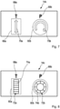
- the aperture component 14b according to 7 has information objects 68a, 68b, which in principle can be formed by one of the display elements 30 of the display layer 24 or by one of the operating symbols 46 of the cover layer 20. Furthermore, the panel component 14b has discrete display elements in the form of pictograms 70a, 70b.
- the pictograms 70a, 70b can, for example, be illuminated displays or illuminated symbols.
- fields 60a, 60b of the sensor layer 22 (cf. 6 ) can be defined or selected in such a way that a first field 60a extends in an area in which the pictogram 60a is arranged.
- a field 60b can extend in an area in which the icon 70b is arranged. The operator can now make his inputs directly via the pictograms 70a, 70b, which can also show him the desired type of input.
- the operator can make a swipe or slide movement in field 60a, which is based on pictogram 70a, which represents a double arrow. In this way, the operator can select a temperature, for example.
- Icon 70b illustrates a circular arrow. In this way, it can be shown to the operator that he can select a program, for example, by means of a swiping movement along a circular path. That based on 7
- the illustrated embodiment may be coupled to another display (not shown) to provide the operator with feedback regarding his input.
- the panel component 14c is provided, for example, with information objects 68a, 68b, which can be designed as printed or similarly designed operating symbols.
- the screen component 14c has display elements in the form of segment displays 72a, 72b which (logically) are connected to defined fields 60a, 60b of the sensor layer 22 (cf. 6 ) are linked.
- Each of the segment displays 72a, 72b can be formed from a plurality of selectively activatable segments 74a, 74b.
- the segment displays 72a, 72b and the fields 60a, 60b assigned to them can be linked to one another in such a way that a user can make an entry directly on the respective display.
- the operator can activate one of the segments 74a, 74b by touching it or a similar gesture. Feedback to the operator can be provided without any significant time delay by activating or deactivating the corresponding segment 74a, 74b.
- the segment display 72a can function as a bar display, for example.
- the bar graph can show a temperature level, for example.
- the operator can select a desired temperature level by touching or "swiping", which is immediately reported back to him by a corresponding activation of the segments 74a of the segment display 72a.
- the operator can select such a desired program by selecting one of the segments 74b. This can be illustrated to him immediately after his choice by visually highlighting the selected or deselected segment 74b.
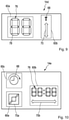
- the screen component 14d can also have operating symbols that are attached to the associated covering layer (cf. 4 ) are visually and/or haptically perceptible. This can be about be a print 68.
- the imprint 68 can, for example, identify a linked field 60b that is located in the area of a pictogram that is designed as an illuminated symbol 72, for example. Together, the imprint 68 and the illuminated symbol 70 can guide the operator in his input.
- a selected (control) panel 60 can in principle also only be linked to a passive control symbol, such as passive printing or the like, without the (control) panel 60 being assigned an (active) display element.
- a corresponding imprint can, for example, include a symbol and an identification of the area in which the user can make his entries or make his selection.
- the panel component 14d also has a segment display 76, which is designed in particular as a 7-segment display.
- the segment display 76 has a plurality of segments 78 .
- a corresponding field 60a for operator inputs is assigned to the 7-segment display 76 . It is conceivable that the operator can make entries directly on the display 76 in field 60a, for example by selectively activating or deactivating one of the segments 78. It is also conceivable that the segment display 76 is used to provide feedback to the operator, if this is the case makes entries above the pictogram 70 in field 60b.
- FIG. 14 illustrates a further configuration of a panel component 14e, which can have various display elements and operating symbols for operator guidance.
- an operating symbol in the form of printing 68 depicting a clock is provided.
- the field 60b can be assigned to a 7-segment display 76, for example.
- the field 60b can also cover a pictogram or illuminated symbol 70b on which the operator can make his entries. Feedback can be given directly via the 7-segment display 76.
- the bezel member 14e further includes a panel 60a positioned over an icon 70a.
- the icon 70a can show the operator, for example, that he can make entries in field 60a in order to scale or adjust the input sensitivity in field 60b.
- the operator can reduce or increase the sensitivity for time entries in field 60a by means of a "zoom gesture".
- highly accurate input can be provided where desired.
- the active objects 70, 72 and 76 are illustrated than display elements can be arranged in the display layer 24 . These elements can be activated selectively and thus be perceived visually through the sensor layer 22 and the cover layer 20 by the operator.
- 11 and 12 12 illustrate an advantageous exemplary embodiment of an operating assembly 80 that makes use of various aspects of the present disclosure.
- the representation according to 11 illustrates an exemplary layout of a control arrangement 80 for a washing machine or similar household appliance.
- the representation according to 12 based on the 11 illustrated layout. 12 however, illustrates that according to the design 11 underlying principles in abstract form.
- the operating arrangement 80 claims only one operating panel 12 or only one panel component 14, which can make use of various aspects of the present disclosure.
- the operating arrangement 80 can be referred to as an integrated operating arrangement.
- This essentially has the advantage that an expanded operator functionality or display functionality can be provided with just one component or a complex of components. It is not necessary to add separate display elements, operating elements and the like to an "assembled" panel component 14 .
- the input functionality only requires one sensor layer (see also 2 ) in order to be able to record and evaluate a large number of different operator inputs.
- the control arrangements 80 illustrated each comprise a plurality of control areas 82.
- the control arrangements include, for example a first operating area 82a, a second operating area 82b and a third operating area 82c.
- At least one field 60 for recording operator inputs can be assigned to each of the operating areas 82 .
- a plurality of fields 60 can be assigned to at least one of the operating areas 82 . Illustrated only as an example 12 that the first operating area 82a is assigned a field 60a, the second operating area 82b is assigned a field 60b and the third operating area 82c is assigned a field 60c.
- the fields 60 can be understood as corresponding assignments on the sensor layer 22 for detecting operator inputs.
- the fields 60 can therefore represent a defined subset of the sensor layer 22 .
- Each of the operating areas 22 can have at least one visual display element 30 for visual emphasis and/or user guidance. However, it is also preferred that at least one of the operating areas 82 is provided with elements for haptic perception or for haptic emphasis.
- An example of a haptic highlight 84 in relief is in 11 indicated in top view.
- the haptic highlighting 84 is assigned to the first operating area 82a.
- the haptic highlighting 84 can be embodied, for example, as an elevation or depression in the form of a ring or ring section, which is assigned to the planar extension of the first operating area 82a.
- the haptic highlighting 84 can be designed in the form of a relief, for example as a circular circumferential groove, and can characterize the dimensions of the first operating area 82a in a haptically perceptible manner.
- the operator can “feel” the haptic highlighting 84 with his fingertip, for example, and is guided haptically by the highlighting 84 when making his input, for example on a ring track or ring segment track.
- the first operating area 82a can also be identified visually in order to guide the user or to show the user his input.
- at least the display element 30a assigned to the first operating area 82a can be used.
- the operating areas 82a, 82b, 82c of the 11 and 12 illustrated layouts interact in a suitable manner to enable the user on the one hand a quick and intuitive operation and on the other hand to provide a variety of input options.
- the first operating area 82a can be designed as a so-called rotary control.
- a ring-shaped or ring-section-shaped field 60a (cf. 12 ) are assigned to the operating area 82a.
- a control device 42 assigned to the operating arrangement 80 (cf. e.g 3 and 4 ) are controlled in a specific way in order to detect operator inputs in the first operating area 82a.
- the operator can thus make inputs, for example by tapping or swiping on the circular ring or circular ring section provided by the first operating arrangement 80a.
- These inputs can include the selection of process variables, in particular the selection of specific values from relatively large value ranges.
- the user can make a temperature selection, a time selection, a speed selection or similar inputs in the first operating area 82a by swiping or tapping.
- the first operating area 82a is linked to at least one display element 30a.
- a likewise circular or ring-shaped arrangement of display elements 30 is preferably provided in the first operating area 82a.
- This can be, for example, light-emitting diodes (LEDs) and similar display elements.
- the first operating area 82a can be used in a manner similar to a circle chart or pie chart to illustrate a currently selected value within a value range with specific limits. This can be displayed to the user immediately during his input.
- the value or the pie chart can preferably be influenced directly by tapping or swiping, it being possible for associated display elements 30 to be selectively controlled directly at the current point of contact in order to provide “feedback”.
- the operating elements 30 assigned to the first operating area 82a are designed to display information in different colors. Accordingly, different light-emitting diodes or light-emitting diodes with different filters can be used to display different colors. Furthermore, mixed colors can be generated at least approximately by selectively driving different-colored light-emitting diodes. It would also be conceivable to use and specifically control so-called RGB LEDs in order to display different colors.
- the ability to highlight certain portions of the first control area 82a in different colors can be used to advantage.
- the user can be provided with visual support for his input when preselecting a temperature by means of known associations (e.g. cold: blue and hot: red).
- known associations e.g. cold: blue and hot: red
- Particularly energy-saving inputs (or selected program/operating parameters) could be identified by green highlights, for example.
- Energy-intensive inputs (or selected program/operating parameters) could accordingly be marked by red highlights.
- a color progression (for example from red to green or from red to blue) can be displayed on the first operating area 82a itself, and the point at which this point can also be displayed to the operator of the color gradient or at which value of the range of values on which the gradient is based it is currently located.
- the first operating area 82a can also be used to show a remaining running time, a countdown (for example until the start of a preselected program) and in a similar way.
- a filling level (detergent supply, a supply of fabric softener or a supply of a descaling agent) could also be displayed in the first operating area 82a.
- a current program progress can also be displayed via the display elements 30 assigned to the first operating area 82a.
- the second operating area 82b is, for example, the 11 and 12 around an area that is delimited or enclosed by the first operating area 82a.
- the second operating area 82b can include at least one assigned field 60b for recording user inputs.
- At least one corresponding display element 30b can be assigned to the second operating area 82b.
- the at least one display element 30b for the second operating area 82b can, for example, comprise a segment display, in particular a 7-segment display.
- the second operating area 82b can include display elements 30 which are designed as discrete display elements, pictograms or in a similar manner and can preferably be optically activated. Optical activation can include backlighting, for example.
- the second operating area 82b can be designed to display information which, for example, reflects a value that the user has selected in the first operating area 82a.
- the representation can in particular include a numeric or alphanumeric representation.
- the segment display can be used for this purpose. In other words, a selected temperature, a selected time or duration and/or a selected program can be displayed in the second operating area 82b.
- basic status information can be displayed in the second operating area 82b.
- this may include basic program functionality such as START, STOP, PAUSE, and the like.
- the second operating area 82b is also designed to record user inputs.
- the field 60b assigned to the second operating area 82b can also be monitored and evaluated for detecting operator inputs.
- operator inputs can be made in field 60b by tapping or swiping, cf. the double arrows labeled 88 in FIG 12 . In this way, too, the operator can select values from value ranges.
- a graphics-capable display can be provided in the second operating area 82b.
- the second operating area 82b can be designed to display pixel-based graphics.
- a corresponding display can be designed as an LCD display, TFT display, OLED display or in a similar way.
- Such a display can also be combined with the sensor layer 22 in order to detect operator inputs in the field 60b assigned to the second operating area 82b and to display information in the second operating area 82b in response to the operator inputs.
- the operating arrangement 80 can comprise a third operating area 82c.
- the third operating area 82c can be coupled to at least one corresponding field 60c for operator inputs.
- the third operating area 82c preferably has a number of fields 60 for operator inputs.
- the third operating area 82c can include various quick selection functions that can be selected or deselected by tapping or approaching.
- each field 60 assigned to the third operating area 82c can include at least one display element 30c that can be selectively activated.
- the display element 30c can include a pictogram or a predefined alphanumeric representation that can be selectively activated, in particular can be illuminated. The operator can make a quick selection by specifically tapping on the desired field 60c of the third operating area 82c.
- the associated indicator 30c may be activated to provide visual feedback to the operator.
- the third operating area 82c can include frequently selected functions that can be directly selected particularly quickly. In this way, the operation of the household appliance 10 can be further simplified.
- a conceivable piece of alphanumeric information that can be presented to the operator in the third operating area 82c is denoted by 90.
- An exemplary icon that can be presented to the operator in the third operating area 82c is denoted by 92 .
- Conceivable operating modes can include an inactive mode, an activatable mode and an activated mode. At least some of the modes of operation may be visually highlighted.
- An inactive mode is to be understood as meaning a mode in which no entries are possible in the field 30 currently linked to the display element 30 .
- the corresponding display element 30 is then preferably “optically” deactivated or at least hidden. This can also be done by assigning a specific color. In this way, the operator can be informed immediately that the current field 60 is not for input or selection operations is available.
- the display element 30 When the display element 30 can be activated, the field 60 linked to it is currently available for input. In this way, the operator can be shown that he can or should make a selection in principle.
- the mode that can be activated can be identified, for example, by being highlighted with reduced brightness of the display element or with a specific color assigned to the mode that can be activated.
- the activated mode of the indicator 30 may indicate that the field 60 associated with the indicator 30 has been selected by the operator.
- the display element 30 In the activated mode, the display element 30 preferably has a high brightness or a high contrast to its surroundings. It is also conceivable to highlight the display element 30 in a specific color in the activated mode.
- the prescribed modes are suitable in particular for the third operating area 82c, which can include various quick selection options, but can in principle be used for the display elements described within the scope of this disclosure.
- a panel component 14 and a control panel 12 provided with it which are designed according to various aspects mentioned and described above.
- a panel component is provided, which includes a sensor layer covered by a cover layer, which is designed to detect operator inputs and in particular operator gestures.
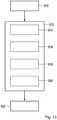
- step S12 can include a (partial) step S14, in which a field, which includes a section or a subset of the sensor layer, is defined and assigned for evaluation.
- step S16 which includes the activation of at least one discrete display element in order to visually illustrate the currently activated field for the operator's inputs.
- a (partial) step S18 can be provided in step S12, which includes the assignment of a selected (control) field to an operating symbol that is provided on the cover layer of the screen component.
- the operating symbol can be a printed operating symbol or something similar.
- a field can be assigned to the operating symbol (in terms of software or circuitry), which in principle can be freely selected in the area of the sensor layer.
- Step S12 can also include an optional (partial) step S20, which includes outputting feedback to the operator.
- At least one discrete display element can be controlled or activated for this purpose. In this way, the operator's input can be immediately identified visually.
- the at least one display element is arranged in the area of the currently assigned field for operator inputs. The operator can thus get the impression that he is making his inputs “directly” on the display element.
- Step S12 can be followed by a step S22, which includes the detection and evaluation of the operator inputs in the field that is currently defined and to be evaluated.
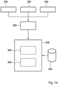
- Step S30 includes the provision of a cover layer, in particular a cover layer made of a plastic material.
- Step S32 includes the provision of a sensor layer that can be activated in sections, in particular a sensor layer that extends over a surface area and is designed to detect operator inputs, in particular operator gestures.
- Step S34 includes providing a display layer that includes at least one discrete display element that is selectively activatable.
- Steps S30, S32 and S34 can be followed by a step S36, which includes the joining of the covering layer, the sensor layer and the display layer.
- the sensor layer can be arranged on a side of the covering layer which faces away from the operator (in normal operation).
- the display layer with the at least one discrete display element can be arranged on the side of the sensor layer facing away from the operator.
- a step S38 can follow, which includes an assignment of at least one defined field on the sensor layer depending on a desired input mode.
- fields can be selected and defined on the sensor layer 22 which are associated with at least one discrete display element.
- fields can also be selected that are assigned to operating symbols or similar symbols that can be perceived visually and/or haptically and that are provided on the covering layer.
- Step S38 can take place in a particularly flexible manner in order to implement a large number of variants based on a given sensor layer.
- Step S38 can include a step S40, which includes providing an interface for driving the sensor layer and, if necessary, for driving the at least one discrete display element. Furthermore, step S38 can include the provision and setup of a control device, as illustrated by step S42. A control unit can be linked via the interface to the combination of cover layer, sensor layer and, if present, display layer.
- a data base or database can be used, cf. the reference symbol S44. A plurality of potentially possible configurations including respective input modes can be stored in the database.
- a system can be flexibly assigned and configured in step S38, which includes the panel component and the control device linked to it via the interface or the associated control device.
- the control device can be configured in terms of software and/or hardware.
- the sensor layer which is provided flat on the cover layer, allows a free and flexible configuration for a large number of different operator inputs.
- the sensor layer if present, can be used for user guidance and interaction with the user/operator.
- the operator can also be offered the possibility of making complex operator inputs with comparatively simply designed discrete display elements or with operating symbols provided on the covering layer. In particular, this can be done without complex pixel-based display elements, so that the production can be done with reduced effort.
Landscapes
- Engineering & Computer Science (AREA)
- General Engineering & Computer Science (AREA)
- Theoretical Computer Science (AREA)
- Human Computer Interaction (AREA)
- Physics & Mathematics (AREA)
- General Physics & Mathematics (AREA)
- Chemical & Material Sciences (AREA)
- Combustion & Propulsion (AREA)
- Mechanical Engineering (AREA)
- Textile Engineering (AREA)
- User Interface Of Digital Computer (AREA)
- Push-Button Switches (AREA)
Claims (14)
- Procédé de guidage d'opérateur sélectif destiné à des entrées d'opérateur dans un appareil ménager (10), le procédé comprenant les étapes suivantes :- fournir un composant de panneau (14) comprenant une couche de détection (22) qui est recouverte par une couche de revêtement (20), qui s'étend de manière bidimensionnelle et qui est conçue pour détecter des entrées d'opérateur se présentant sous la forme de gestes d'opérateur,
la couche de détection (22) pouvant être activée par endroits,
le composant de panneau (14) ayant une configuration de base et pouvant être commandé d'une manière spécifique à la variante,- définir un mode d'entrée en cours, comprenant les opérations suivantes :- affecter de manière flexible, par une technique logicielle ou câblée, au moins une zone définie à évaluer (60), qui correspond à une partie de la couche de détection (22), à des entrées d'opérateur se présentant sous la forme de gestes d'opérateur sur la couche de détection (22) en fonction du mode d'entrée souhaité,- activer au moins un élément d'affichage discret (30) d'une couche d'affichage (24) disposée du côté de la couche de détection (22) qui est opposé à la couche de revêtement (20) pour identifier la zone à évaluer (60) de la couche de détection (22),
l'au moins un élément d'affichage discret (30) étant un élément d'affichage non à base de pixels, et- détecter et évaluer des entrées d'opérateur dans la zone à évaluer (60). - Procédé selon la revendication 1, l'étape de définition du mode d'entrée en cours comprenant en outre l'étape suivante :- associer la zone à évaluer (60), destinée aux entrées d'opérateur, à un symbole de commande (46) qui est perceptible de manière visuelle et/ou haptique sur la couche de revêtement (20).
- Procédé selon l'une quelconque des revendications précédentes, comprenant en outre :- la délivrance d'un retour visuel à l'opérateur en réponse à une entrée d'opérateur par activation sélective d'au moins un élément d'affichage discret (30) non à base de pixels de la couche d'affichage (24).
- Composant de panneau (14) destiné à un panneau de commande (12) destiné à un appareil ménager (10) pour mettre en œuvre un procédé selon la revendication 1, le composant de panneau (14) comprenant :- une couche de revêtement (20),- une couche de détection (22) pouvant être activée par endroits et recouvrant au moins par endroits de manière bidimensionnelle un côté arrière de la couche de revêtement (20),- une couche d'affichage (24) pourvue d'au moins un élément d'affichage discret (30), l'au moins un élément d'affichage discret (30) étant un élément d'affichage non à base de pixels,
la couche de détection (22) étant interposée entre la couche de revêtement (20) et l'au moins un élément d'affichage discret (30) non à base de pixels,
le composant de panneau (14) ayant une configuration de base et pouvant être commandé d'une manière spécifique à la variante,
la couche de détection (22) étant conçue pour détecter des entrées d'opérateur se présentant sous la forme de gestes d'opérateur, la couche de détection (22) pouvant être activée par endroits en fonction d'un mode d'entrée souhaité, au moins une zone définie à évaluer (60), qui correspond à une partie de la couche de détection (22), pouvant être affectée de manière flexible, par une technique logicielle ou câblée, à des entrées d'opérateur sur la couche de détection (22) et l'au moins un élément d'affichage discret (30) non à base de pixels pouvant être commandé pour effectuer un guidage d'opérateur sélectif. - Composant de panneau (14) selon la revendication 4, la couche de détection (22) étant conçue comme une couche de détection capacitive (22) et étant conçue pour détecter des contacts sur la couche de revêtement (20) et/ou des approches de la couche de revêtement (20) dans la région de la couche de détection (22).
- Composant de panneau (14) selon la revendication 4 ou 5, comprenant en outre une interface (36) destinée à un dispositif de commande (42) qui est conçu pour commander sélectivement la couche de détection (22) et l'au moins un élément d'affichage discret (30) non à base de pixels, afin de définir une pluralité de modes d'entrée, le dispositif de commande (42) étant conçu pour définir un mode d'entrée en cours et, en prenant en compte au moins un mode d'entrée sélectionné, pour affecter au moins une zone à évaluer (60) destinée à des entrées d'opérateur sur la couche de détection (22).
- Composant de panneau (14) selon l'une des revendications 4 à 6, comprenant au moins un élément d'affichage (30) non à base de pixels, qui est conçu comme un symbole discret (68, 70) pouvant être activé sélectivement ou comme un affichage à segments discret (72, 76) pouvant être activé sélectivement, notamment comme un affichage à sept segments.
- Composant de panneau (14) selon l'une des revendications 4 à 7, la couche de revêtement (20) et la couche de détection (22) étant au moins par endroits transparentes ou translucides, et la couche de revêtement (20) étant au moins par endroits traitée en surface, en particulier imprimée ou revêtue, et la couche de revêtement (20) comportant au moins un symbole de commande (46) perceptible de manière visuelle et/ou haptique pour effectuer le guidage d'opérateur.
- Dispositif de commande (80) destiné à un appareil ménager (10) et comprenant un composant de panneau (14) selon l'une des revendications 4 à 8, le dispositif de commande (80) comprenant une pluralité de régions de commande définies (82) qui sont formées en particulier au niveau du composant de panneau (14), et au moins une zone (60) destinée à des entrées d'opérateur et au moins un élément d'affichage (30) discret, non à base de pixels étant associés à chaque région de commande (82).
- Dispositif de commande (80) selon la revendication 9, le composant de panneau (14) étant conçu comme un composant de panneau d'intégration (14) dans lequel les régions de commande (82) sont intégrées, au moins une première région de commande (82a) et une deuxième région de commande (82b) étant prévues, la première région de commande (82a) comprenant un actionneur commandable par geste et des éléments d'affichage (30a) discrets, non à base de pixels, destinés à mettre en évidence de manière visuelle une région de réglage, et la deuxième région de commande (82b) comprenant un affichage multifonctionnel pourvu d'au moins un élément d'affichage (30b) discrets, non à base de pixels, qui est au moins conçu pour afficher une valeur sélectionnée au niveau de la première région de commande (82a).
- Dispositif de commande (80) selon la revendication 10, les éléments d'affichage (30a) discrets, non à base de pixels, de la première région de commande (82a) étant adaptés pour effectuer un changement de couleur ou un changement de dégradé de couleurs en réponse à une entrée d'opérateur, et la deuxième région de commande (82b) étant en outre adaptée pour détecter des entrées d'opérateur se présentant sous la forme de gestes d'opérateur et pour afficher des informations en réponse aux entrées d'opérateur.
- Dispositif de commande (80) selon l'une des revendications 10 ou 11, au moins une des régions de commande (82) étant mise en évidence de manière haptique, une mise en évidence (84) perceptible de manière haptique étant formée sur la couche de revêtement (20), et la mise en évidence haptique (84) comprenant de préférence une dépression et/ou une élévation dans la région de commande identifiée (82).
- Procédé de fabrication d'un composant de panneau (14) d'un panneau de commande (12) destiné à un appareil ménager (10), le composant de panneau (14) ayant une configuration de base et pouvant être commandé d'une manière spécifique à la variante, le procédé comprenant les étapes suivantes :- fournir une couche de revêtement (20) en matière plastique,- fournir une couche de détection (22) qui peut être activée par endroits, qui s'étend de manière bidimensionnelle et qui est conçue pour détecter des entrées d'opérateur se présentant sous la forme de gestes d'opérateur,- fournir au moins un élément d'affichage discret (30), l'au moins un élément d'affichage discret (30) étant un élément d'affichage non à base de pixels,- assembler la couche de revêtement (20), la couche de détection (22) et l'au moins un élément d'affichage discret (30) non à base de pixels, la couche de détection (22) étant interposée entre la couche de revêtement (20) et l'au moins un élément d'affichage discret (30) non à base de pixels, et- fournir une interface (36) destinée à un dispositif de commande (42) destiné à commander l'au moins un élément d'affichage discret (30) non à base de pixels et à évaluer des entrées d'opérateur détectées au niveau de la couche de détection (22) pour effectuer un guidage d'opérateur sélectif, et- affecter de manière flexible, par une technique logicielle ou câblée, au moins une zone à évaluer (60), qui correspond à une partie de la couche de détection (22), à des entrées d'opérateur sur la couche de détection (22) en fonction d'une configuration d'entrée souhaitée du composant de panneau (14).
- Procédé selon la revendication 13, comprenant en outre les étapes suivantes :- traiter, en particulier imprimer ou revêtir, la couche de revêtement (20) pour générer au moins un symbole de commande (46) perceptible de manière visuelle et/ou haptique pour effectuer le guidage d'opérateur, et- affecter au moins une zone à évaluer (60) à des entrées d'opérateur sur la couche de détection (22) en fonction d'une taille et/ou d'un agencement de l'au moins un symbole de commande (46) perceptible de manière visuelle et/ou haptique pour effectuer un guidage d'opérateur sélectif.
Priority Applications (1)
| Application Number | Priority Date | Filing Date | Title |
|---|---|---|---|
| PL14196990T PL2884187T5 (pl) | 2013-12-10 | 2014-12-09 | Sposób prowadzenia użytkownika, element panelu i wytwarzanie elementu panelu |
Applications Claiming Priority (2)
| Application Number | Priority Date | Filing Date | Title |
|---|---|---|---|
| DE102013113772.5A DE102013113772A1 (de) | 2013-12-10 | 2013-12-10 | Verfahren zur Bedienerführung, Blendenbauteil, Herstellung eines Blendenbauteils sowie Haushaltsgerät mit einem Blendenbauteil |
| DE201420101897 DE202014101897U1 (de) | 2013-12-10 | 2014-04-22 | Einrichtung zur Bedienerführung, Blendenbauteil, Bedienanordnung sowie Haushaltsgerät mit einem Blendenbauteil |
Publications (3)
| Publication Number | Publication Date |
|---|---|
| EP2884187A1 EP2884187A1 (fr) | 2015-06-17 |
| EP2884187B1 EP2884187B1 (fr) | 2019-05-01 |
| EP2884187B2 true EP2884187B2 (fr) | 2022-03-09 |
Family
ID=52738403
Family Applications (1)
| Application Number | Title | Priority Date | Filing Date |
|---|---|---|---|
| EP14196990.7A Active EP2884187B2 (fr) | 2013-12-10 | 2014-12-09 | Procédé d'aide à l'utilisateur, composant d'écran, fabrication d'un composant d'écran et appareil ménager doté d'un composant d'écran |
Country Status (6)
| Country | Link |
|---|---|
| US (1) | US9983783B2 (fr) |
| EP (1) | EP2884187B2 (fr) |
| CN (1) | CN104699384B (fr) |
| DE (2) | DE102013113772A1 (fr) |
| ES (1) | ES2739799T5 (fr) |
| PL (1) | PL2884187T5 (fr) |
Families Citing this family (28)
| Publication number | Priority date | Publication date | Assignee | Title |
|---|---|---|---|---|
| US10649557B2 (en) | 2013-12-10 | 2020-05-12 | Pas Deutschland Gmbh | Method for operator guidance, control panel component, production of a control panel component and home appliance comprising a control panel component |
| CN106325079A (zh) * | 2015-06-16 | 2017-01-11 | 中兴通讯股份有限公司 | 家电设备的控制方法和装置 |
| DE102015216167A1 (de) | 2015-08-25 | 2017-03-02 | BSH Hausgeräte GmbH | Haushaltsgerät mit Befestigungssystem, hierfür geeignetes Befestigungssystem sowie Verfahren zur Herstellung des Haushaltsgerätes |
| DE102015121904B4 (de) * | 2015-12-16 | 2025-10-16 | Pictiva Displays International Limited | Optoelektronische Bauelementevorrichtung, Verfahren zum Herstellen einer optoelektronischen Bauelementevorrichtung und Verfahren zum Betreiben einer optoelektronischen Bauelementevorrichtung |
| ES2628607B1 (es) * | 2015-12-22 | 2018-05-14 | Bsh Electrodomésticos España, S.A. | Dispositivo de aparato doméstico |
| DE102016203781A1 (de) | 2016-03-08 | 2017-09-14 | BSH Hausgeräte GmbH | Haushaltsgerät mit berührsensitiver Bedienfläche zum Einstellen eines Werts eines Betriebsparameters durch Relativbewegungen von Einstellelementen sowie Verfahren zum Einstellen eines Betriebsparameters |
| JP6776616B2 (ja) * | 2016-05-23 | 2020-10-28 | 富士ゼロックス株式会社 | 作業案内装置及びプログラム |
| EP3270065A1 (fr) * | 2016-07-14 | 2018-01-17 | Electrolux Appliances Aktiebolag | Interface utilisateur pour appareil domestique |
| CN106012417A (zh) * | 2016-07-29 | 2016-10-12 | 无锡小天鹅股份有限公司 | 洗衣机及其控制装置和控制方法 |
| DE102016214642B4 (de) * | 2016-08-08 | 2024-02-29 | BSH Hausgeräte GmbH | Haushaltsgerät mit Touchdrehwähler, Verfahren zu seiner Herstellung und Verfahren zu seinem Betrieb |
| DE102016221259A1 (de) * | 2016-10-28 | 2018-05-03 | BSH Hausgeräte GmbH | Bedienvorrichtung mit großem berührsensitiven Schieberegler, Haushaltsgerät sowie Verfahren zum Betreiben eines Haushaltsgeräts |
| US10757766B2 (en) * | 2016-11-30 | 2020-08-25 | Illinois Tool Works, Inc. | RF oven control and interface |
| US10691334B2 (en) | 2016-12-29 | 2020-06-23 | Whirlpool Corporation | Cooking device with interactive display |
| DE102017111580A1 (de) | 2017-05-29 | 2018-11-29 | Miele & Cie. Kg | Blendenelement und elektrisches Haushaltsgerät mit einem solchen Blendenelement |
| DE102017211059A1 (de) * | 2017-06-29 | 2019-01-03 | BSH Hausgeräte GmbH | Wäschepflegegerät mit einem Anzeigeelement |
| US11256412B2 (en) * | 2018-03-09 | 2022-02-22 | Dixell S.R.L. | Interactive touch display assembly including a display stack with a multi-layer capacitive keyboard overlaid on a 7-segment display |
| DE102018209950A1 (de) * | 2018-06-20 | 2019-12-24 | BSH Hausgeräte GmbH | Steuervorrichtung für ein Hausgerät |
| US10851487B2 (en) | 2018-06-28 | 2020-12-01 | Midea Group Co., Ltd. | Appliance with context-sensitive fixed-position user interface |
| DE102018216481A1 (de) * | 2018-09-26 | 2020-03-26 | BSH Hausgeräte GmbH | Gargerät mit einem ringförmigen, berührsensitiven Bedienbereich und einem berührsensitiven Bedienstreifen, sowie Verfahren zum Betreiben eines Gargeräts |
| KR102694170B1 (ko) * | 2018-12-28 | 2024-08-13 | 삼성전자주식회사 | 식기세척기 |
| KR102526148B1 (ko) * | 2019-06-23 | 2023-04-26 | 와틀로 일렉트릭 매뉴팩츄어링 컴파니 | 산업용 제어 투영 용량성 터치 인터페이스 |
| CN110989834B (zh) * | 2019-11-26 | 2022-12-23 | 广东美的厨房电器制造有限公司 | 烹饪设备及其手势控制方法 |
| US11113933B1 (en) * | 2020-02-28 | 2021-09-07 | Therm-Omega-Tech, Inc. | Visual indication system for feedback controller |
| DE102020215166A1 (de) * | 2020-12-02 | 2022-06-02 | BSH Hausgeräte GmbH | Bedieneinheit für ein Haushaltsgerät |
| CN112680927B (zh) * | 2020-12-16 | 2022-03-29 | 珠海格力电器股份有限公司 | 一种转动装置及具有其的控制面板、洗衣机 |
| DE202021001890U1 (de) | 2021-05-28 | 2021-07-26 | Pas Deutschland Gmbh | Spezielle Ausgestaltung von kapazitiven Sensoren zur berührungslosen und berührenden Bedienung eines elektrischen Toilettensitzes |
| WO2025023524A1 (fr) * | 2023-07-27 | 2025-01-30 | 삼성전자 주식회사 | Lave-linge et appareil électroménager comprenant une carte de circuit imprimé pour panneau d'interface utilisateur prenant en charge à la fois une clé électronique et une clé mécanique dans une zone unique |
| DE102024123808A1 (de) | 2024-08-20 | 2026-02-26 | Preh Gmbh | Bedieneinrichtung mit berührempfindlichem Bedienfeld und Pixelmatrixanzeige mit zum Bedienfeld gehörigem Anzeigeteilbereich und Funktionsüberwachung, deren Verwendung sowie zugehöriges Verfahren |
Citations (12)
| Publication number | Priority date | Publication date | Assignee | Title |
|---|---|---|---|---|
| US6626013B2 (en) † | 2001-02-28 | 2003-09-30 | Hitachi, Ltd. | Washing machine, display/operation panel, and household appliance with the display/operation panel |
| US7030860B1 (en) † | 1999-10-08 | 2006-04-18 | Synaptics Incorporated | Flexible transparent touch sensing system for electronic devices |
| EP1876394A2 (fr) † | 2006-07-03 | 2008-01-09 | BSH Bosch und Siemens Hausgeräte GmbH | Bande d'affichage avec une structure haptique en relief |
| US20080235614A1 (en) † | 2007-03-23 | 2008-09-25 | Electrolux Home Products | Appliance with user interface having multi-user mode |
| DE102008020995A1 (de) † | 2008-04-25 | 2009-10-29 | Convotherm Elektrogeräte GmbH | Gargerät und Verfahren zum Bedienen eines Gargeräts |
| DE102008026481A1 (de) † | 2008-06-03 | 2009-12-10 | Convotherm Elektrogeräte GmbH | Gargerät |
| DE102008051265A1 (de) † | 2008-10-10 | 2010-04-15 | Wmf Württembergische Metallwarenfabrik Ag | Steuerungs-, Regelungs- und Bedienvorrichtung für ein Gargerät |
| DE102009006224A1 (de) † | 2009-01-27 | 2010-07-29 | Rational Ag | Verfahren zur Auswahl und Anordnung von Programmen, Gargerät hierfür und Küchennetzwerk hiermit |
| DE102010060295A1 (de) † | 2010-11-02 | 2012-05-10 | Miele & Cie. Kg | Programmgesteuertes Haushaltsgerät mit einer Bedien- und Anzeigeeinrichtung |
| DE202012101770U1 (de) † | 2012-01-17 | 2012-05-29 | Atmel Corp. | Auf Display befindliche Sensor-Schichtanordnung |
| DE102011081332A1 (de) † | 2011-08-22 | 2013-02-28 | BSH Bosch und Siemens Hausgeräte GmbH | Haushaltsgerät mit einer berührungssensitiven Bedien- und Anzeigeeinrichtung |
| EP1994216B1 (fr) † | 2006-03-16 | 2013-11-06 | PAS Deutschland GmbH | Agencement de bandeau de commande pour des appareils ménagers et procédé de fabrication d'un agencement de bandeau de commande |
Family Cites Families (19)
| Publication number | Priority date | Publication date | Assignee | Title |
|---|---|---|---|---|
| US3819906A (en) * | 1972-12-26 | 1974-06-25 | Gen Motors Corp | Domestic range control and display system |
| US5943044A (en) * | 1996-08-05 | 1999-08-24 | Interlink Electronics | Force sensing semiconductive touchpad |
| US6355194B1 (en) * | 1999-03-22 | 2002-03-12 | Xerox Corporation | Carrier pelletizing processes |
| US6355914B1 (en) * | 1999-03-30 | 2002-03-12 | Edward E. Stockley | Programmable oven with menu selection |
| DE10011645A1 (de) | 2000-03-10 | 2001-09-13 | Ego Elektro Geraetebau Gmbh | Berührungsschalter mit einem LC-Display |
| US6765557B1 (en) * | 2000-04-10 | 2004-07-20 | Interlink Electronics, Inc. | Remote control having touch pad to screen mapping |
| DE10133135C5 (de) | 2001-07-07 | 2012-11-15 | Electrolux Professional Ag | Stelleinheit für Gargeräte |
| JP2003344086A (ja) * | 2002-05-28 | 2003-12-03 | Pioneer Electronic Corp | タッチパネル装置及び自動車用表示入力装置 |
| DE102004020824A1 (de) * | 2004-04-28 | 2005-12-01 | BSH Bosch und Siemens Hausgeräte GmbH | Stellvorrichtung mit einem zumindest zweidimensionalen Sen-sorbereich |
| DE102005018298A1 (de) | 2005-04-15 | 2006-10-19 | E.G.O. Elektro-Gerätebau GmbH | Verfahren zur Ansteuerung und/oder Auswertung eines länglichen Sensorelements einer Bedieneinrichtung und eine solche Bedieneinrichtung |
| DE102005032088A1 (de) | 2005-07-08 | 2007-01-18 | BSH Bosch und Siemens Hausgeräte GmbH | Hausgerät, insbesondere Gargerät mit berührungsempfindlichem Stellstreifen |
| CN102418947B (zh) | 2006-07-27 | 2014-06-18 | 松下电器产业株式会社 | 加热烹调器 |
| KR20100015501A (ko) * | 2007-03-15 | 2010-02-12 | 에프-오리진, 인크. | 힘 감응 터치 스크린의 마찰 없는 이동을 위한 집적된 특성 |
| EP2048781B1 (fr) * | 2007-10-08 | 2018-06-13 | Whirlpool Corporation | Interrupteur tactile pour appareils électriques et appareil électrique doté d'un tel interrupteur |
| DE102008032451C5 (de) | 2008-07-10 | 2017-10-19 | Rational Ag | Anzeigeverfahren und Gargerät hierfür |
| US20100145483A1 (en) * | 2008-12-05 | 2010-06-10 | Mcgonagle Michael Paul | Human-machine interface assembly for an appliance |
| US20110012845A1 (en) * | 2009-07-20 | 2011-01-20 | Rothkopf Fletcher R | Touch sensor structures for displays |
| EP2461645B1 (fr) * | 2009-07-27 | 2019-04-10 | Panasonic Corporation | Dispositif de fonctionnement et appareil de cuisson utilisant le dispositif de fonctionnement |
| US8804344B2 (en) * | 2011-06-10 | 2014-08-12 | Scott Moncrieff | Injection molded control panel with in-molded decorated plastic film |
-
2013
- 2013-12-10 DE DE102013113772.5A patent/DE102013113772A1/de not_active Ceased
-
2014
- 2014-02-28 US US14/193,094 patent/US9983783B2/en active Active
- 2014-03-14 CN CN201410097511.XA patent/CN104699384B/zh active Active
- 2014-04-22 DE DE201420101897 patent/DE202014101897U1/de not_active Expired - Lifetime
- 2014-12-09 EP EP14196990.7A patent/EP2884187B2/fr active Active
- 2014-12-09 PL PL14196990T patent/PL2884187T5/pl unknown
- 2014-12-09 ES ES14196990T patent/ES2739799T5/es active Active
Patent Citations (12)
| Publication number | Priority date | Publication date | Assignee | Title |
|---|---|---|---|---|
| US7030860B1 (en) † | 1999-10-08 | 2006-04-18 | Synaptics Incorporated | Flexible transparent touch sensing system for electronic devices |
| US6626013B2 (en) † | 2001-02-28 | 2003-09-30 | Hitachi, Ltd. | Washing machine, display/operation panel, and household appliance with the display/operation panel |
| EP1994216B1 (fr) † | 2006-03-16 | 2013-11-06 | PAS Deutschland GmbH | Agencement de bandeau de commande pour des appareils ménagers et procédé de fabrication d'un agencement de bandeau de commande |
| EP1876394A2 (fr) † | 2006-07-03 | 2008-01-09 | BSH Bosch und Siemens Hausgeräte GmbH | Bande d'affichage avec une structure haptique en relief |
| US20080235614A1 (en) † | 2007-03-23 | 2008-09-25 | Electrolux Home Products | Appliance with user interface having multi-user mode |
| DE102008020995A1 (de) † | 2008-04-25 | 2009-10-29 | Convotherm Elektrogeräte GmbH | Gargerät und Verfahren zum Bedienen eines Gargeräts |
| DE102008026481A1 (de) † | 2008-06-03 | 2009-12-10 | Convotherm Elektrogeräte GmbH | Gargerät |
| DE102008051265A1 (de) † | 2008-10-10 | 2010-04-15 | Wmf Württembergische Metallwarenfabrik Ag | Steuerungs-, Regelungs- und Bedienvorrichtung für ein Gargerät |
| DE102009006224A1 (de) † | 2009-01-27 | 2010-07-29 | Rational Ag | Verfahren zur Auswahl und Anordnung von Programmen, Gargerät hierfür und Küchennetzwerk hiermit |
| DE102010060295A1 (de) † | 2010-11-02 | 2012-05-10 | Miele & Cie. Kg | Programmgesteuertes Haushaltsgerät mit einer Bedien- und Anzeigeeinrichtung |
| DE102011081332A1 (de) † | 2011-08-22 | 2013-02-28 | BSH Bosch und Siemens Hausgeräte GmbH | Haushaltsgerät mit einer berührungssensitiven Bedien- und Anzeigeeinrichtung |
| DE202012101770U1 (de) † | 2012-01-17 | 2012-05-29 | Atmel Corp. | Auf Display befindliche Sensor-Schichtanordnung |
Also Published As
| Publication number | Publication date |
|---|---|
| US20150160850A1 (en) | 2015-06-11 |
| CN104699384A (zh) | 2015-06-10 |
| EP2884187B1 (fr) | 2019-05-01 |
| PL2884187T3 (pl) | 2019-10-31 |
| ES2739799T5 (es) | 2022-05-06 |
| DE202014101897U1 (de) | 2015-03-11 |
| CN104699384B (zh) | 2018-11-13 |
| ES2739799T3 (es) | 2020-02-04 |
| PL2884187T5 (pl) | 2022-07-11 |
| EP2884187A1 (fr) | 2015-06-17 |
| US9983783B2 (en) | 2018-05-29 |
| DE102013113772A1 (de) | 2015-06-11 |
Similar Documents
| Publication | Publication Date | Title |
|---|---|---|
| EP2884187B2 (fr) | Procédé d'aide à l'utilisateur, composant d'écran, fabrication d'un composant d'écran et appareil ménager doté d'un composant d'écran | |
| EP2723930B1 (fr) | Dispositif de commande et d'affichage d'un appareil menager et appareil menager | |
| EP3372435B1 (fr) | Procédé et système de commande destinés à fournir une interface utilisateur | |
| EP2748369B1 (fr) | Appareil ménager à système de commande et d'affichage tactile | |
| EP3270278A1 (fr) | Procede de fonctionnement d'un systeme de commande et systeme de commande | |
| DE102019204046B4 (de) | Vorrichtung und Verfahren zur Ausgabe eines Parameterwerts in einem Fahrzeug | |
| WO2004109005A1 (fr) | Dispositif pour selectionner des fonctions et procede de commande d'un appareil electrique | |
| EP2182636A2 (fr) | Dispositif de commande d'un appareil ménager | |
| EP3237251B1 (fr) | Interface utilitsateur pour unmoyen de transport comprenant un rail pour les doigts et les moyens de transport qui l'utilisent | |
| DE102008032449A1 (de) | Anzeigeverfahren und Gargerät hierfür | |
| EP2748368B1 (fr) | Appareil électroménager équipé d'un dispositif de commande et d'affichage tactile | |
| EP3947008A1 (fr) | Dispositif et procédé pour la détection d'une entrée d'un utilisateur dans un véhicule | |
| EP1830132A2 (fr) | Procédé destiné à la commande d'un appareil ménager, en particulier d'un four ménager, et dispositif de commande et d'affichage | |
| EP3947009A1 (fr) | Procédé et dispositif de détection d'une valeur de paramètre dans un véhicule | |
| DE102019213211A1 (de) | Bediensystem für ein Fahrzeug und Verfahren zum Betreiben eines Bediensystems für ein Fahrzeug | |
| DE102013015227A1 (de) | Bedieneinrichtung für einen Kraftwagen | |
| EP3805643B1 (fr) | Dispositif de commande pour un appareil électroménager destiné à la détection tactile et sans contact du changement de capacité, appareil électroménager ainsi que procédé | |
| BE1030351B1 (de) | Haushaltsgerät, vorzugsweise Küchengerät, besonders vorzugsweise Kochfeld | |
| EP3947007A1 (fr) | Procédé et dispositif de réglage d'une valeur de paramètre dans un véhicule | |
| DE102019204049A1 (de) | Vorrichtung und Verfahren zum Einstellen eines Parameterwerts in einem Fahrzeug | |
| DE102012105624A1 (de) | Bedieneinrichtung für multifunktionale Maschinen und Verfahren zur Erleichterung einer Betätigung einer Bedieneinrichtung |
Legal Events
| Date | Code | Title | Description |
|---|---|---|---|
| PUAI | Public reference made under article 153(3) epc to a published international application that has entered the european phase |
Free format text: ORIGINAL CODE: 0009012 |
|
| 17P | Request for examination filed |
Effective date: 20141209 |
|
| AK | Designated contracting states |
Kind code of ref document: A1 Designated state(s): AL AT BE BG CH CY CZ DE DK EE ES FI FR GB GR HR HU IE IS IT LI LT LU LV MC MK MT NL NO PL PT RO RS SE SI SK SM TR |
|
| AX | Request for extension of the european patent |
Extension state: BA ME |
|
| R17P | Request for examination filed (corrected) |
Effective date: 20151215 |
|
| RBV | Designated contracting states (corrected) |
Designated state(s): AL AT BE BG CH CY CZ DE DK EE ES FI FR GB GR HR HU IE IS IT LI LT LU LV MC MK MT NL NO PL PT RO RS SE SI SK SM TR |
|
| STAA | Information on the status of an ep patent application or granted ep patent |
Free format text: STATUS: EXAMINATION IS IN PROGRESS |
|
| 17Q | First examination report despatched |
Effective date: 20170208 |
|
| GRAP | Despatch of communication of intention to grant a patent |
Free format text: ORIGINAL CODE: EPIDOSNIGR1 |
|
| STAA | Information on the status of an ep patent application or granted ep patent |
Free format text: STATUS: GRANT OF PATENT IS INTENDED |
|
| INTG | Intention to grant announced |
Effective date: 20181114 |
|
| GRAS | Grant fee paid |
Free format text: ORIGINAL CODE: EPIDOSNIGR3 |
|
| GRAA | (expected) grant |
Free format text: ORIGINAL CODE: 0009210 |
|
| STAA | Information on the status of an ep patent application or granted ep patent |
Free format text: STATUS: THE PATENT HAS BEEN GRANTED |
|
| AK | Designated contracting states |
Kind code of ref document: B1 Designated state(s): AL AT BE BG CH CY CZ DE DK EE ES FI FR GB GR HR HU IE IS IT LI LT LU LV MC MK MT NL NO PL PT RO RS SE SI SK SM TR |
|
| REG | Reference to a national code |
Ref country code: GB Ref legal event code: FG4D Free format text: NOT ENGLISH |
|
| REG | Reference to a national code |
Ref country code: CH Ref legal event code: EP Ref country code: AT Ref legal event code: REF Ref document number: 1127439 Country of ref document: AT Kind code of ref document: T Effective date: 20190515 |
|
| REG | Reference to a national code |
Ref country code: DE Ref legal event code: R096 Ref document number: 502014011572 Country of ref document: DE |
|
| REG | Reference to a national code |
Ref country code: IE Ref legal event code: FG4D Free format text: LANGUAGE OF EP DOCUMENT: GERMAN |
|
| REG | Reference to a national code |
Ref country code: NL Ref legal event code: MP Effective date: 20190501 |
|
| REG | Reference to a national code |
Ref country code: LT Ref legal event code: MG4D |
|
| PG25 | Lapsed in a contracting state [announced via postgrant information from national office to epo] |
Ref country code: NO Free format text: LAPSE BECAUSE OF FAILURE TO SUBMIT A TRANSLATION OF THE DESCRIPTION OR TO PAY THE FEE WITHIN THE PRESCRIBED TIME-LIMIT Effective date: 20190801 Ref country code: HR Free format text: LAPSE BECAUSE OF FAILURE TO SUBMIT A TRANSLATION OF THE DESCRIPTION OR TO PAY THE FEE WITHIN THE PRESCRIBED TIME-LIMIT Effective date: 20190501 Ref country code: SE Free format text: LAPSE BECAUSE OF FAILURE TO SUBMIT A TRANSLATION OF THE DESCRIPTION OR TO PAY THE FEE WITHIN THE PRESCRIBED TIME-LIMIT Effective date: 20190501 Ref country code: FI Free format text: LAPSE BECAUSE OF FAILURE TO SUBMIT A TRANSLATION OF THE DESCRIPTION OR TO PAY THE FEE WITHIN THE PRESCRIBED TIME-LIMIT Effective date: 20190501 Ref country code: AL Free format text: LAPSE BECAUSE OF FAILURE TO SUBMIT A TRANSLATION OF THE DESCRIPTION OR TO PAY THE FEE WITHIN THE PRESCRIBED TIME-LIMIT Effective date: 20190501 Ref country code: PT Free format text: LAPSE BECAUSE OF FAILURE TO SUBMIT A TRANSLATION OF THE DESCRIPTION OR TO PAY THE FEE WITHIN THE PRESCRIBED TIME-LIMIT Effective date: 20190901 Ref country code: NL Free format text: LAPSE BECAUSE OF FAILURE TO SUBMIT A TRANSLATION OF THE DESCRIPTION OR TO PAY THE FEE WITHIN THE PRESCRIBED TIME-LIMIT Effective date: 20190501 Ref country code: LT Free format text: LAPSE BECAUSE OF FAILURE TO SUBMIT A TRANSLATION OF THE DESCRIPTION OR TO PAY THE FEE WITHIN THE PRESCRIBED TIME-LIMIT Effective date: 20190501 |
|
| PG25 | Lapsed in a contracting state [announced via postgrant information from national office to epo] |
Ref country code: BG Free format text: LAPSE BECAUSE OF FAILURE TO SUBMIT A TRANSLATION OF THE DESCRIPTION OR TO PAY THE FEE WITHIN THE PRESCRIBED TIME-LIMIT Effective date: 20190801 Ref country code: RS Free format text: LAPSE BECAUSE OF FAILURE TO SUBMIT A TRANSLATION OF THE DESCRIPTION OR TO PAY THE FEE WITHIN THE PRESCRIBED TIME-LIMIT Effective date: 20190501 Ref country code: LV Free format text: LAPSE BECAUSE OF FAILURE TO SUBMIT A TRANSLATION OF THE DESCRIPTION OR TO PAY THE FEE WITHIN THE PRESCRIBED TIME-LIMIT Effective date: 20190501 Ref country code: GR Free format text: LAPSE BECAUSE OF FAILURE TO SUBMIT A TRANSLATION OF THE DESCRIPTION OR TO PAY THE FEE WITHIN THE PRESCRIBED TIME-LIMIT Effective date: 20190802 |
|
| PG25 | Lapsed in a contracting state [announced via postgrant information from national office to epo] |
Ref country code: IS Free format text: LAPSE BECAUSE OF FAILURE TO SUBMIT A TRANSLATION OF THE DESCRIPTION OR TO PAY THE FEE WITHIN THE PRESCRIBED TIME-LIMIT Effective date: 20190901 |
|
| PG25 | Lapsed in a contracting state [announced via postgrant information from national office to epo] |
Ref country code: SK Free format text: LAPSE BECAUSE OF FAILURE TO SUBMIT A TRANSLATION OF THE DESCRIPTION OR TO PAY THE FEE WITHIN THE PRESCRIBED TIME-LIMIT Effective date: 20190501 Ref country code: CZ Free format text: LAPSE BECAUSE OF FAILURE TO SUBMIT A TRANSLATION OF THE DESCRIPTION OR TO PAY THE FEE WITHIN THE PRESCRIBED TIME-LIMIT Effective date: 20190501 Ref country code: RO Free format text: LAPSE BECAUSE OF FAILURE TO SUBMIT A TRANSLATION OF THE DESCRIPTION OR TO PAY THE FEE WITHIN THE PRESCRIBED TIME-LIMIT Effective date: 20190501 Ref country code: EE Free format text: LAPSE BECAUSE OF FAILURE TO SUBMIT A TRANSLATION OF THE DESCRIPTION OR TO PAY THE FEE WITHIN THE PRESCRIBED TIME-LIMIT Effective date: 20190501 Ref country code: DK Free format text: LAPSE BECAUSE OF FAILURE TO SUBMIT A TRANSLATION OF THE DESCRIPTION OR TO PAY THE FEE WITHIN THE PRESCRIBED TIME-LIMIT Effective date: 20190501 |
|
| REG | Reference to a national code |
Ref country code: DE Ref legal event code: R026 Ref document number: 502014011572 Country of ref document: DE |
|
| REG | Reference to a national code |
Ref country code: ES Ref legal event code: FG2A Ref document number: 2739799 Country of ref document: ES Kind code of ref document: T3 Effective date: 20200204 |
|
| PLBI | Opposition filed |
Free format text: ORIGINAL CODE: 0009260 |
|
| PLAX | Notice of opposition and request to file observation + time limit sent |
Free format text: ORIGINAL CODE: EPIDOSNOBS2 |
|
| PG25 | Lapsed in a contracting state [announced via postgrant information from national office to epo] |
Ref country code: SM Free format text: LAPSE BECAUSE OF FAILURE TO SUBMIT A TRANSLATION OF THE DESCRIPTION OR TO PAY THE FEE WITHIN THE PRESCRIBED TIME-LIMIT Effective date: 20190501 |
|
| 26 | Opposition filed |
Opponent name: BSH HAUSGERAETE GMBH Effective date: 20200203 |
|
| PG25 | Lapsed in a contracting state [announced via postgrant information from national office to epo] |
Ref country code: SI Free format text: LAPSE BECAUSE OF FAILURE TO SUBMIT A TRANSLATION OF THE DESCRIPTION OR TO PAY THE FEE WITHIN THE PRESCRIBED TIME-LIMIT Effective date: 20190501 |
|
| PLBB | Reply of patent proprietor to notice(s) of opposition received |
Free format text: ORIGINAL CODE: EPIDOSNOBS3 |
|
| REG | Reference to a national code |
Ref country code: CH Ref legal event code: PL |
|
| REG | Reference to a national code |
Ref country code: BE Ref legal event code: MM Effective date: 20191231 |
|
| PG25 | Lapsed in a contracting state [announced via postgrant information from national office to epo] |
Ref country code: MC Free format text: LAPSE BECAUSE OF FAILURE TO SUBMIT A TRANSLATION OF THE DESCRIPTION OR TO PAY THE FEE WITHIN THE PRESCRIBED TIME-LIMIT Effective date: 20190501 |
|
| GBPC | Gb: european patent ceased through non-payment of renewal fee |
Effective date: 20191209 |
|
| PG25 | Lapsed in a contracting state [announced via postgrant information from national office to epo] |
Ref country code: FR Free format text: LAPSE BECAUSE OF NON-PAYMENT OF DUE FEES Effective date: 20191231 Ref country code: GB Free format text: LAPSE BECAUSE OF NON-PAYMENT OF DUE FEES Effective date: 20191209 Ref country code: IE Free format text: LAPSE BECAUSE OF NON-PAYMENT OF DUE FEES Effective date: 20191209 Ref country code: LU Free format text: LAPSE BECAUSE OF NON-PAYMENT OF DUE FEES Effective date: 20191209 |
|
| PG25 | Lapsed in a contracting state [announced via postgrant information from national office to epo] |
Ref country code: LI Free format text: LAPSE BECAUSE OF NON-PAYMENT OF DUE FEES Effective date: 20191231 Ref country code: CH Free format text: LAPSE BECAUSE OF NON-PAYMENT OF DUE FEES Effective date: 20191231 Ref country code: BE Free format text: LAPSE BECAUSE OF NON-PAYMENT OF DUE FEES Effective date: 20191231 |
|
| REG | Reference to a national code |
Ref country code: AT Ref legal event code: MM01 Ref document number: 1127439 Country of ref document: AT Kind code of ref document: T Effective date: 20191209 |
|
| RIC2 | Information provided on ipc code assigned after grant |
Ipc: F24C 7/08 20060101AFI20210414BHEP Ipc: D06F 34/32 20200101ALI20210414BHEP Ipc: G06F 3/044 20060101ALI20210414BHEP Ipc: H03K 17/96 20060101ALI20210414BHEP |
|
| PG25 | Lapsed in a contracting state [announced via postgrant information from national office to epo] |
Ref country code: CY Free format text: LAPSE BECAUSE OF FAILURE TO SUBMIT A TRANSLATION OF THE DESCRIPTION OR TO PAY THE FEE WITHIN THE PRESCRIBED TIME-LIMIT Effective date: 20190501 Ref country code: AT Free format text: LAPSE BECAUSE OF NON-PAYMENT OF DUE FEES Effective date: 20191209 |
|
| PG25 | Lapsed in a contracting state [announced via postgrant information from national office to epo] |
Ref country code: MT Free format text: LAPSE BECAUSE OF FAILURE TO SUBMIT A TRANSLATION OF THE DESCRIPTION OR TO PAY THE FEE WITHIN THE PRESCRIBED TIME-LIMIT Effective date: 20190501 Ref country code: HU Free format text: LAPSE BECAUSE OF FAILURE TO SUBMIT A TRANSLATION OF THE DESCRIPTION OR TO PAY THE FEE WITHIN THE PRESCRIBED TIME-LIMIT; INVALID AB INITIO Effective date: 20141209 |
|
| PUAH | Patent maintained in amended form |
Free format text: ORIGINAL CODE: 0009272 |
|
| STAA | Information on the status of an ep patent application or granted ep patent |
Free format text: STATUS: PATENT MAINTAINED AS AMENDED |
|
| 27A | Patent maintained in amended form |
Effective date: 20220309 |
|
| AK | Designated contracting states |
Kind code of ref document: B2 Designated state(s): AL AT BE BG CH CY CZ DE DK EE ES FI FR GB GR HR HU IE IS IT LI LT LU LV MC MK MT NL NO PL PT RO RS SE SI SK SM TR |
|
| REG | Reference to a national code |
Ref country code: DE Ref legal event code: R102 Ref document number: 502014011572 Country of ref document: DE |
|
| REG | Reference to a national code |
Ref country code: ES Ref legal event code: DC2A Ref document number: 2739799 Country of ref document: ES Kind code of ref document: T5 Effective date: 20220506 |
|
| PG25 | Lapsed in a contracting state [announced via postgrant information from national office to epo] |
Ref country code: MK Free format text: LAPSE BECAUSE OF FAILURE TO SUBMIT A TRANSLATION OF THE DESCRIPTION OR TO PAY THE FEE WITHIN THE PRESCRIBED TIME-LIMIT Effective date: 20190501 |
|
| P01 | Opt-out of the competence of the unified patent court (upc) registered |
Effective date: 20230425 |
|
| PGFP | Annual fee paid to national office [announced via postgrant information from national office to epo] |
Ref country code: IT Payment date: 20251223 Year of fee payment: 12 |
|
| PGFP | Annual fee paid to national office [announced via postgrant information from national office to epo] |
Ref country code: TR Payment date: 20251202 Year of fee payment: 12 |
|
| PGFP | Annual fee paid to national office [announced via postgrant information from national office to epo] |
Ref country code: PL Payment date: 20251120 Year of fee payment: 12 |
|
| REG | Reference to a national code |
Ref country code: DE Ref legal event code: R081 Ref document number: 502014011572 Country of ref document: DE Owner name: BSH HAUSGERAETE GMBH, DE Free format text: FORMER OWNER: PAS DEUTSCHLAND GMBH, 16816 NEURUPPIN, DE Ref country code: DE Ref legal event code: R082 Ref document number: 502014011572 Country of ref document: DE |
|
| PGFP | Annual fee paid to national office [announced via postgrant information from national office to epo] |
Ref country code: ES Payment date: 20260119 Year of fee payment: 12 |
|
| PGFP | Annual fee paid to national office [announced via postgrant information from national office to epo] |
Ref country code: DE Payment date: 20251223 Year of fee payment: 12 |