EP2183434B1 - Améliorations apportées à et concernant des poteaux de sécurité - Google Patents
Améliorations apportées à et concernant des poteaux de sécurité Download PDFInfo
- Publication number
- EP2183434B1 EP2183434B1 EP08793951.8A EP08793951A EP2183434B1 EP 2183434 B1 EP2183434 B1 EP 2183434B1 EP 08793951 A EP08793951 A EP 08793951A EP 2183434 B1 EP2183434 B1 EP 2183434B1
- Authority
- EP
- European Patent Office
- Prior art keywords
- post
- region
- frangible
- weakness
- jaws
- Prior art date
- Legal status (The legal status is an assumption and is not a legal conclusion. Google has not performed a legal analysis and makes no representation as to the accuracy of the status listed.)
- Active
Links
Images


Classifications
-
- E—FIXED CONSTRUCTIONS
- E01—CONSTRUCTION OF ROADS, RAILWAYS, OR BRIDGES
- E01F—ADDITIONAL WORK, SUCH AS EQUIPPING ROADS OR THE CONSTRUCTION OF PLATFORMS, HELICOPTER LANDING STAGES, SIGNS, SNOW FENCES, OR THE LIKE
- E01F9/00—Arrangement of road signs or traffic signals; Arrangements for enforcing caution
- E01F9/60—Upright bodies, e.g. marker posts or bollards; Supports for road signs
- E01F9/623—Upright bodies, e.g. marker posts or bollards; Supports for road signs characterised by form or by structural features, e.g. for enabling displacement or deflection
- E01F9/631—Upright bodies, e.g. marker posts or bollards; Supports for road signs characterised by form or by structural features, e.g. for enabling displacement or deflection specially adapted for breaking, disengaging, collapsing or permanently deforming when deflected or displaced, e.g. by vehicle impact
- E01F9/635—Upright bodies, e.g. marker posts or bollards; Supports for road signs characterised by form or by structural features, e.g. for enabling displacement or deflection specially adapted for breaking, disengaging, collapsing or permanently deforming when deflected or displaced, e.g. by vehicle impact by shearing or tearing, e.g. having weakened zones
-
- E—FIXED CONSTRUCTIONS
- E01—CONSTRUCTION OF ROADS, RAILWAYS, OR BRIDGES
- E01F—ADDITIONAL WORK, SUCH AS EQUIPPING ROADS OR THE CONSTRUCTION OF PLATFORMS, HELICOPTER LANDING STAGES, SIGNS, SNOW FENCES, OR THE LIKE
- E01F15/00—Safety arrangements for slowing, redirecting or stopping errant vehicles, e.g. guard posts or bollards; Arrangements for reducing damage to roadside structures due to vehicular impact
- E01F15/02—Continuous barriers extending along roads or between traffic lanes
- E01F15/04—Continuous barriers extending along roads or between traffic lanes essentially made of longitudinal beams or rigid strips supported above ground at spaced points
- E01F15/0461—Supports, e.g. posts
-
- Y—GENERAL TAGGING OF NEW TECHNOLOGICAL DEVELOPMENTS; GENERAL TAGGING OF CROSS-SECTIONAL TECHNOLOGIES SPANNING OVER SEVERAL SECTIONS OF THE IPC; TECHNICAL SUBJECTS COVERED BY FORMER USPC CROSS-REFERENCE ART COLLECTIONS [XRACs] AND DIGESTS
- Y10—TECHNICAL SUBJECTS COVERED BY FORMER USPC
- Y10T—TECHNICAL SUBJECTS COVERED BY FORMER US CLASSIFICATION
- Y10T29/00—Metal working
- Y10T29/49—Method of mechanical manufacture
- Y10T29/49789—Obtaining plural product pieces from unitary workpiece
- Y10T29/4979—Breaking through weakened portion
Definitions
- the present invention relates to improvements in and relating to frangible posts.
- the invention relates to a method of producing a frangible post by compressing a portion of the post.
- the present invention also includes posts formed by such a method and barriers including such posts.
- frangible post(s) may be required.
- a post that can provide sufficient to withstand a typical a side-on impact between an errant vehicle and the barrier.
- the post provides the barrier with the ability to redirect the vehicle.
- the same post should be sufficiently Weakened so as to yield during end-on impacts between an errant vehicle and the barrier, to thereby in most cases reduce the severity of impact forces experienced by the occupants of the vehicle.
- US 6,516,573 discloses a support post having a breakaway system in the form of a series of grooves or indentations which allow the post to fail on impact from any direction.
- GB 2431955 discloses a folding safety post for supporting articles including a slot passing horizontally through the post to create a hinge.
- the inventor of the present invention has found that by forming an indent in via compression of a portion of a post, a suitable region of weakness is created to allow the post to deform in the area of the indent when the post is subjected to a sufficient force in a pre-determined direction.
- 'frangible' refers to a situation where a post is broken or deformed into an unusable state.
- the post may be broken or deformed by breaking the post into two or more parts, or by bending the post out of shape.
- the post may be formed from steel or wood, however this should not be seen as limiting.
- the cross sections of the frangible post may be an 'I' or 'T' configuration.
- the post may be formed by multiple members that are integrally connected or welded together.
- the notch or notches may have a V shape.
- indent and notch will now be used interchangeably through out the specification, and this should not be seen as departing from the scope of the present invention.
- the notch or notches may be located on at least one lateral axis or side of the post or post member(s) at least one point along the length of the post. It will be appreciated that a person skilled in the art will know of the preferred positions for the notches, so the post is frangible upon application of a force at the desired angle.
- the notch or notches may be located substantially close to ground level. However, this should not be seen as limiting.
- the frangible post comprises at least two notches on a post member.
- the notches may be substantially opposed to one another on different sides or edges of the post member.
- the notches may be mirror images of each other. In other preferred embodiments, the notches may alternate on different sides along the length of the posts, edges or lateral axes.
- the reduced width of the region of weakness may be a thickness of at least one tenth of the initial post width.
- the width of the post member may be reduced from 5mm to 0.5mm.
- the width of indent may vary depending on the original width of the post member(s) and the degree of frangibility required.
- the compressing action may produce substantially little or no residue material from the post.
- the compressing action may be achieved by a tool with jaws wherein such that the length and/or configuration region of weakness are always formed in the substantially same plane on each post member.
- the jaws will have suitable projections, preferably with an inverse shape to that of the desired shape of the indent or notches.
- the projections resemble an inverted V-shape.
- the post may be positioned into a press which is equipped with jaws substantially as described above.
- the post members are positioned so each jaw sits either side of the post members.
- the jaws are then pressed together, for example by hydraulic rams, until the correct depth of indent is achieved.
- the correct depth is achieved by having a suitable stop to ensure the jaws can only compress press the projections into the post member a set distance.
- the notch or notches may be formed after the post is positioned in the ground. While in other embodiments, the notch or notches may be formed prior to the post being positioned in the ground.
- the post may be compressed following the placement the posts forming the barrier.
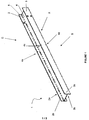
- FIGS 1 to 3 show a post 1.
- Post 1 is in an 'I' configuration, with two post members 2 and 3 connected in parallel by a central post member 4.
- the central post member 4 is positioned substantially within the centre of members 2 and 3 along line 5.
- Each post member 2 and 3 has two surfaces indicated by 2a / 2b and 3a / 3b respectively.
- Each surface 2a / 2b and 3a / 3b of post members 2 and 3 has region of weakness formed by a series of indents 4a to 4d (indent 4b is not visible in the drawings). As shown, the indents 4a to 4d are located substantially at the end of each post member 2 and 3.
- Indent 4c is formed by two V-shaped notches 41 and 42 on surfaces 3a and 3b of member 3. Both notches 41 and 42 have a central point 43 and 44 respectively which are flanked by arms 45, 46, 47 and 48.
- Notches 41 and 42 are formed by compressing the surfaces 3a and 3b of post member 3 in the directions of arrows Y and U. This compression results in the 9 central points 43 and 44 of the indents 41 and 42 to form a region of the post having a reduced width, as indicated by arrows Z 1 and Z 2 with respect to the non-compressed surfaces of the post member.
- the post 1 is positioned in the ground such that post members 2 and 3 are parallel with, and post member 4 is perpendicular to, the road (not shown) and rails (not shown) forming the barrier.
- the post 1 is placed in the ground with a suitable amount of the post members protruding from the ground.
- the indents 4a to 4d are then be formed in the surface of post members 2 and 3 by compressing a portion of the post members 2 and 3 in the required place by a suitable tool (not shown).
- the notches are formed by a press (not shown) having two jaws which are "pressed” together by hydraulic rams, to a set distance dictated by a suitable stop.
- the jaws of the tool contain suitable triangular shaped projections.
- the post members 2 and 3 are placed, at the required position, into the jaws of the press.
- the jaws are then closed together so the projections press into the post members 2 and/or 3 to form the indents 4a to 4d having the required depth as dictated by the stop.
- the notches 4a to 4d allow members 2 and 3 of the post 1 to collapse and/or fail.
- the post will retain tensile strength.
Landscapes
- Engineering & Computer Science (AREA)
- Architecture (AREA)
- Civil Engineering (AREA)
- Structural Engineering (AREA)
- Press Drives And Press Lines (AREA)
- Containers Having Bodies Formed In One Piece (AREA)
Claims (17)
- Poteau cassable (1) pour une barrière routière latérale comprenant au moins deux éléments de poteau (2, 3, 4) agencés perpendiculairement entre eux, dans lequel le premier élément de poteau (2, 3) comprend une région de faiblesse formée par compression d'au moins une surface et/ou bord du poteau, ladite région ayant une largeur réduite par rapport à une largeur d'origine du poteau (1) dans cette région,
caractérisé en ce que les au moins deux éléments de poteau sont agencés perpendiculairement entre eux de sorte que le poteau (1) comprend une section transversale ayant une configuration en « I » ou en « T », dans lequel la région de faiblesse dans le premier élément de poteau (2, 3) comprend au moins une indentation (4a) se présentant sous la forme d'au moins deux encoches (41, 42), chacune positionnée sur un axe latéral du premier élément de poteau (2, 3) au niveau d'un point le long d'une longueur du poteau (1), et sensiblement opposées entre elles sur des côtés ou bords différents du premier élément de poteau (2, 3), dans lequel la région de faiblesse est agencée de sorte que le poteau (1) est cassable dans la région de faiblesse suite à un impact de collision sensiblement perpendiculaire à l'axe latéral du premier élément de poteau (2, 3), et dans lequel le poteau (1) conserve la résistance à la traction suite à l'impact de collision sensiblement parallèle à l'axe latéral du premier élément de poteau (2, 3). - Poteau cassable (1) selon la revendication 1, dans lequel les éléments de poteau (1) sont raccordés de manière solidaire ou soudés ensemble.
- Poteau cassable (1) selon la revendication 1 ou 2, dans lequel les encoches (41, 42) ont une forme de V.
- Poteau cassable (1) selon l'une quelconque des revendications précédentes, dans lequel l'indentation (4a) est positionnée sensiblement proche du niveau du sol.
- Poteau cassable (1) selon l'une quelconque des revendications précédentes, dans lequel le poteau comprend des indentations (4a, 4b) alternant sur différents côtés (2, 3) le long de la longueur du poteau (1).
- Poteau cassable (1) selon l'une quelconque des revendications précédentes, dans lequel les encoches (41, 42) sont des images en miroir l'une de l'autre.
- Poteau cassable (1) selon l'une quelconque des revendications précédentes, dans lequel la largeur réduite formant la région de faiblesse est une épaisseur d'au moins un dixième de la largeur du poteau initiale.
- Barrière comprenant au moins un poteau cassable (1) selon l'une quelconque des revendications précédentes.
- Procédé pour produire un poteau cassable selon l'une quelconque des revendications 1 à 7, le procédé comprenant l'étape consistant à sertir les surfaces ou bords (2) du premier élément de poteau (2, 3) pour former la région de faiblesse.
- Procédé selon la revendication 9, dans lequel le sertissage produit sensiblement peu ou pas de matériau résiduel par rapport au poteau (1).
- Procédé selon la revendication 9 ou 10, dans lequel le sertissage est obtenu par un outil avec des mâchoires, dans lequel la longueur et/ou la configuration des mâchoires est telle que la région de faiblesse est toujours formée sensiblement dans le même plan sur chaque poteau (1).
- Procédé selon la revendication 11, dans lequel les mâchoires ont des saillies appropriées, avec une forme inversée par rapport à celle de la forme souhaitée des indentations.
- Procédé selon la revendication 12, dans lequel les saillies ressemblent à une forme de V inversé.
- Procédé selon l'une quelconque des revendications 11 à 13, dans lequel le poteau (1) est positionné de sorte que la mâchoire s'installe de chaque côté des éléments de poteau, les mâchoires sont ensuite comprimées ensemble, jusqu'à l'obtention d'une profondeur correcte de l'indentation.
- Procédé selon la revendication 14, dans lequel la profondeur correcte est obtenue en ayant une butée appropriée pour garantir que les mâchoires peuvent comprimer uniquement les saillies dans le poteau (1) sur une distance de consigne.
- Procédé selon l'une quelconque des revendications 9 à 15, dans lequel le poteau (1) est comprimé suite au déplacement des poteaux formant une barrière.
- Procédé selon les revendications 9 à 16, dans lequel les surfaces ou bords (2) du premier élément de poteau (2, 3) sont sertis in situ.
Applications Claiming Priority (2)
| Application Number | Priority Date | Filing Date | Title |
|---|---|---|---|
| NZ556782A NZ556782A (en) | 2007-07-27 | 2007-07-27 | Method of producing a frangible post |
| PCT/NZ2008/000189 WO2009017427A1 (fr) | 2007-07-27 | 2008-07-28 | Améliorations apportées à et concernant des poteaux fragiles |
Publications (3)
| Publication Number | Publication Date |
|---|---|
| EP2183434A1 EP2183434A1 (fr) | 2010-05-12 |
| EP2183434A4 EP2183434A4 (fr) | 2013-11-06 |
| EP2183434B1 true EP2183434B1 (fr) | 2017-09-13 |
Family
ID=40304542
Family Applications (1)
| Application Number | Title | Priority Date | Filing Date |
|---|---|---|---|
| EP08793951.8A Active EP2183434B1 (fr) | 2007-07-27 | 2008-07-28 | Améliorations apportées à et concernant des poteaux de sécurité |
Country Status (8)
| Country | Link |
|---|---|
| US (1) | US8978225B2 (fr) |
| EP (1) | EP2183434B1 (fr) |
| AU (1) | AU2008283115B2 (fr) |
| CA (1) | CA2694671C (fr) |
| ES (1) | ES2656797T3 (fr) |
| NZ (1) | NZ556782A (fr) |
| WO (1) | WO2009017427A1 (fr) |
| ZA (1) | ZA201001178B (fr) |
Families Citing this family (7)
| Publication number | Priority date | Publication date | Assignee | Title |
|---|---|---|---|---|
| US8757597B2 (en) * | 2010-09-02 | 2014-06-24 | Valmont Highway Technology Limited | Posts |
| US10047488B2 (en) | 2012-10-24 | 2018-08-14 | Energy Absorption Systems, Inc. | Frangible post for highway barrier end terminals |
| US9051699B2 (en) | 2013-01-22 | 2015-06-09 | Fletcher Building Holdings Limited | Pedestrian and vehicle barrier |
| US10818204B2 (en) * | 2013-09-10 | 2020-10-27 | John O'Connor | Pivotable signpost support device |
| US10340735B2 (en) * | 2016-05-09 | 2019-07-02 | Electronics And Telecommunications Research Institute | Method and apparatus for optimal resource allocation based on contribution margin ratio |
| USD891963S1 (en) * | 2018-09-19 | 2020-08-04 | Highway Care Ltd. | Combined T-barrier connector and barrier |
| US11921480B2 (en) * | 2021-03-31 | 2024-03-05 | Hygge Energy Inc. | Optimizing distributed energy resource value |
Family Cites Families (100)
| Publication number | Priority date | Publication date | Assignee | Title |
|---|---|---|---|---|
| US1722994A (en) | 1927-05-05 | 1929-08-06 | American Cable Co Inc | Hitch for wire rope |
| US1828349A (en) | 1930-12-26 | 1931-10-20 | Malleable Iron Fittings Co | Automatic compensating device for highway guard fence cables |
| US1951470A (en) * | 1932-10-29 | 1934-03-20 | Arthur T Cole | Crimping and sealing edge for light gauge sheet materials |
| US2244042A (en) | 1939-10-20 | 1941-06-03 | Logan Co Inc | Sheet metal hinge construction |
| US2561206A (en) | 1949-04-01 | 1951-07-17 | Kaspar Rudolf | Wood screen with lock joints |
| US2976923A (en) | 1958-09-25 | 1961-03-28 | Hirashiki James | Foldable traverse curtain and construction units therefor |
| US3204606A (en) | 1963-11-08 | 1965-09-07 | Ira B Parr | Articulated livestock panels |
| US3350039A (en) | 1965-10-18 | 1967-10-31 | Wilbur D Crater | Clutching means for launching and arresting aircraft and the like |
| US3537687A (en) | 1967-09-25 | 1970-11-03 | Philip Adelman | Garden fence and wall |
| US3617076A (en) | 1967-10-27 | 1971-11-02 | Unistrut Corp | Fastening clamp |
| SE344314B (fr) | 1969-11-14 | 1972-04-10 | Borgs Fabriks Ab | |
| US3776520A (en) | 1972-11-06 | 1973-12-04 | J P C Inc | Energy absorbing highway guardrail |
| US3866397A (en) | 1972-11-27 | 1975-02-18 | Robert L Koziol | Brush eradicator |
| US3912404A (en) | 1975-01-02 | 1975-10-14 | Herbert L Katt | Highway post construction |
| IT1031675B (it) | 1975-02-12 | 1979-05-10 | Snam Progetti | Dispositivo per l assorbimento dell energia d urto |
| US3982734A (en) | 1975-06-30 | 1976-09-28 | Dynamics Research And Manufacturing, Inc. | Impact barrier and restraint |
| US4183317A (en) * | 1977-10-12 | 1980-01-15 | Follick George E | Versatile all purpose barricade structures |
| US4222552A (en) | 1978-10-20 | 1980-09-16 | Matteo Sr George W | Highway guardrail cover |
| US4330106A (en) | 1979-05-02 | 1982-05-18 | Chisholm Douglas B | Guard rail construction |
| US4452431A (en) | 1982-05-19 | 1984-06-05 | Energy Absorption Systems, Inc. | Restorable fender panel |
| CA1178096A (fr) | 1982-12-02 | 1984-11-20 | Robert J. Brema | Cloture modulaire |
| US4681302A (en) | 1983-12-02 | 1987-07-21 | Thompson Marion L | Energy absorbing barrier |
| US4674911A (en) | 1984-06-13 | 1987-06-23 | Energy Absorption Systems, Inc. | Energy absorbing pneumatic crash cushion |
| FR2576047B1 (fr) | 1985-01-14 | 1987-02-13 | Mecanroc | Barriere de protection contre les chutes de pierres avec des cables d'amarrage susceptibles de glisser dans des organes amortisseurs |
| DE8511870U1 (de) | 1985-04-22 | 1986-04-24 | Faber, Hans, 8120 Weilheim | Vorrichtung zur Verlängerung von Pfosten von Verkehrszeichen und sonstigen Straßenschildern |
| US4678166A (en) | 1986-04-24 | 1987-07-07 | Southwest Research Institute | Eccentric loader guardrail terminal |
| US4655434A (en) | 1986-04-24 | 1987-04-07 | Southwest Research Institute | Energy absorbing guardrail terminal |
| US4739971A (en) | 1987-03-05 | 1988-04-26 | Ruane George W | Guard rail assembly |
| US4844424A (en) | 1987-12-21 | 1989-07-04 | Don Knudslien | Fence structure |
| GB2224528B (en) | 1988-11-08 | 1993-02-10 | British Ropes Ltd | Tensioned cable safety fence |
| US5022782A (en) | 1989-11-20 | 1991-06-11 | Energy Absorption Systems, Inc. | Vehicle crash barrier |
| US5123773A (en) | 1990-10-18 | 1992-06-23 | Rose Enterprises Inc. | Stand-alone highway barrier |
| ES2053311T3 (es) | 1990-12-31 | 1994-07-16 | Fatzer Ag | Dispositivo para la amortiguacion de choques para un cable solicitado a traccion, en el caso de caida de piedras y acumulaciones de nieve. |
| US5118056A (en) | 1991-03-22 | 1992-06-02 | Jeanise Dorothy J | Barricade apparatus |
| DE69305085D1 (de) * | 1992-08-10 | 1996-10-31 | Alcan Aluminium Ltd | Geländer |
| US5391016A (en) | 1992-08-11 | 1995-02-21 | The Texas A&M University System | Metal beam rail terminal |
| FR2701046B1 (fr) | 1993-02-02 | 1995-05-12 | Tss | Séparateur de voies déplaçable latéralement. |
| CA2103002C (fr) * | 1993-11-12 | 2000-10-24 | Ernest R. Bodnar | Poutre laminee a chaud et methode de fabrication connexe |
| AU3215295A (en) | 1994-08-12 | 1996-03-14 | Neosoft, A.G. | Nonlinear digital communications system |
| US6022003A (en) * | 1994-11-07 | 2000-02-08 | The Board Of Regents Of The University Of Nebraska | Guardrail cutting terminal |
| US6220575B1 (en) | 1995-01-18 | 2001-04-24 | Trn Business Trust | Anchor assembly for highway guardrail end terminal |
| DK27795A (da) | 1995-03-20 | 1996-09-21 | Gunnar Davidsen | Profilstykke for kabelautoværn |
| US5609327A (en) | 1995-04-03 | 1997-03-11 | Amidon; William D. | Portable fence panel |
| AUPN408495A0 (en) | 1995-07-10 | 1995-08-03 | Bhp Steel (Jla) Pty Limited | Breakaway post connector |
| AU705297B2 (en) | 1995-12-01 | 1999-05-20 | IF3 Pty Limited | Anchor for cables |
| FR2750714B1 (fr) | 1996-07-05 | 2007-11-02 | Sec Envel | Barriere de securite pour voie de circulation de vehicules traversee d'un passage temporaire |
| US6065738A (en) | 1996-11-29 | 2000-05-23 | Brifen Limited | Anchor for cables |
| US5820110A (en) | 1997-03-11 | 1998-10-13 | B & R Erectors, Inc. | Self storing guard rail system for telescopic bleachers |
| US5775675A (en) | 1997-04-02 | 1998-07-07 | Safety By Design, Inc. | Sequential kinking guardrail terminal system |
| US5851005A (en) | 1997-04-15 | 1998-12-22 | Muller; Franz M. | Energy absorption apparatus |
| US5797591A (en) | 1997-04-25 | 1998-08-25 | Energy Absorption Systems, Inc. | Guardrail with improved ground anchor assembly |
| ES2560846T3 (es) | 1997-05-09 | 2016-02-23 | Trinity Industries, Inc. | Poste de soporte desprendible para tratamiento de los extremos de barandas de protección de autopistas |
| US5921021A (en) | 1997-09-11 | 1999-07-13 | Coates; Carl | Lawn border and edging device |
| US6059491A (en) | 1997-11-14 | 2000-05-09 | Striefel; Richard R. | Portable barrier |
| US5967497A (en) * | 1997-12-15 | 1999-10-19 | Energy Absorption Systems, Inc. | Highway barrier and guardrail |
| PT924347E (pt) | 1997-12-22 | 2004-07-30 | Autostrada Del Brennero S P A | Terminal de barreira de seguranca para guardas de seguranca de auto-estradas |
| US6085458A (en) | 1997-12-31 | 2000-07-11 | Gau; Larry J. | Lawn edging |
| US6173943B1 (en) | 1998-04-22 | 2001-01-16 | Energy Absorption Systems, Inc. | Guardrail with slidable impact-receiving element |
| US6149134A (en) | 1998-10-01 | 2000-11-21 | Wisconsin Alumni Research Foundation | Composite material highway guardrail having high impact energy dissipation characteristics |
| SE513130C2 (sv) | 1998-11-27 | 2000-07-10 | Anders Welandsson | Sätt och anordning för att förhindra skador vid påkörning av ändpartiet av ett vägräcke |
| US6398192B1 (en) * | 1999-01-06 | 2002-06-04 | Trn Business Trust | Breakaway support post for highway guardrail end treatments |
| US6516573B1 (en) | 1999-01-06 | 2003-02-11 | Tyco Flow Services Ag | Integrated breakaway for support posts |
| IT1307663B1 (it) | 1999-02-03 | 2001-11-14 | Snoline Spa | Struttura perfezionata di terminale di barriera stradale di sicurezzaad assorbimento graduale dell'energia di impatto |
| US6290427B1 (en) | 1999-02-16 | 2001-09-18 | Carlos M. Ochoa | Guardrail beam with enhanced stability |
| US6401510B1 (en) * | 1999-04-07 | 2002-06-11 | 3M Innovative Properties Company | Method for stamping a part from a multi-layered strip |
| US6382583B1 (en) | 2000-04-18 | 2002-05-07 | Utd Incorporated | Releasable device and method |
| JP2001324725A (ja) | 2000-05-12 | 2001-11-22 | Hitachi Ltd | 液晶表示装置およびその製造方法 |
| US6877349B2 (en) * | 2000-08-17 | 2005-04-12 | Industrial Origami, Llc | Method for precision bending of sheet of materials, slit sheets fabrication process |
| US20020025221A1 (en) | 2000-08-30 | 2002-02-28 | John Johnson | Modular barrier cushion system |
| US6662620B1 (en) * | 2000-09-12 | 2003-12-16 | Black & Decker Inc. | Steel stud crimper |
| SE519725C2 (sv) | 2000-10-27 | 2003-04-01 | Vaegverket Vaegverket Produkti | Stållineräcke samt en metod att sätta upp ett stållineräcke |
| US6729607B2 (en) | 2001-07-19 | 2004-05-04 | Texas A&M University System | Cable release anchor |
| US20040140460A1 (en) | 2001-08-29 | 2004-07-22 | Heimbecker Chad Garrett | Integrated cable guardrail system |
| ITTO20011105A1 (it) | 2001-11-27 | 2003-05-27 | C R F Societa Con Sortile Per | ,,barriera stradale a scomparsa,,. |
| EP1458935B1 (fr) * | 2001-11-30 | 2013-10-16 | The Texas A & M University System | Poteau de support flexible en acier pour glissiere de securite |
| US6948703B2 (en) | 2002-01-30 | 2005-09-27 | The Texas A&M University System | Locking hook bolt and method for using same |
| US6932327B2 (en) | 2002-01-30 | 2005-08-23 | The Texas A&M University System | Cable guardrail release system |
| US7785031B2 (en) | 2002-02-07 | 2010-08-31 | Universal Safety Response, Inc. | Energy absorbing system |
| IL148689A (en) | 2002-03-14 | 2009-11-18 | Sagy Alexander | Collision partitions for roads and a method of assembling them |
| US7234275B1 (en) | 2002-03-27 | 2007-06-26 | Safety By Design, Ltd. | Barrier and barrier system |
| US6962328B2 (en) | 2002-05-28 | 2005-11-08 | Trn Business Trust | Cable safety system |
| US6854716B2 (en) | 2002-06-19 | 2005-02-15 | Trn Business Trust | Crash cushions and other energy absorbing devices |
| FR2846673A1 (fr) | 2002-11-06 | 2004-05-07 | Claude Alix Georges Pomero | Glissiere de securite routiere a double file de profiles solidarises entre eux |
| US6962459B2 (en) | 2003-08-12 | 2005-11-08 | Sci Products Inc. | Crash attenuator with cable and cylinder arrangement for decelerating vehicles |
| GB2406127A (en) * | 2003-09-17 | 2005-03-23 | Hill & Smith Holdings Plc | Road safety barriers |
| NZ528396A (en) | 2003-09-22 | 2006-02-24 | Armorflex Ltd | Guardrail |
| WO2005028757A1 (fr) | 2003-09-22 | 2005-03-31 | Armorflex Limited | Glissiere de securite |
| US7216854B2 (en) | 2004-02-20 | 2007-05-15 | Bryan Thomas R | Modular fence |
| SE528438C2 (sv) | 2004-07-02 | 2006-11-14 | Varmfoerzinkning Ab | Stolpe med uppfångande organ i ett vägräcke med nedre tillplattat parti |
| FR2872834A1 (fr) | 2004-07-06 | 2006-01-13 | Profiles Du Ct Soc Par Actions | Dispositif de montage coulissant d'au moins une lisse de glissiere de securite |
| AU2005285021B2 (en) | 2004-09-15 | 2010-09-16 | Energy Absorption Systems, Inc. | Crash cushion |
| US20060102883A1 (en) | 2004-09-29 | 2006-05-18 | Creative Pultrusions, Inc. | Pultruded composite guardrail |
| CA2601585A1 (fr) * | 2005-03-17 | 2006-09-28 | Industrial Origami, Llc | Structures pliees de precision a haute resistance mecanique et resistant a la fatigue et feuille a cet effet |
| GB2431955A (en) | 2005-11-02 | 2007-05-09 | Richard James Porter | Folding safety post |
| US20070102689A1 (en) * | 2005-11-08 | 2007-05-10 | Alberson Dean C | Cable barrier guardrail system with steel yielding support posts |
| US20070252124A1 (en) | 2006-04-27 | 2007-11-01 | Bryson Products Inc. | Guardrail System |
| US7621165B2 (en) * | 2006-06-29 | 2009-11-24 | Wheeling-Corrugating Company | Crimp tool |
| US7537411B2 (en) | 2007-05-18 | 2009-05-26 | Yodock Jr Leo J | End connector for barrier devices |
| US7445402B1 (en) | 2007-12-18 | 2008-11-04 | Chih-Hung Chen | Barrier plate for highways |
| US8376650B2 (en) * | 2011-03-31 | 2013-02-19 | Mccue Corporation | Bollard assembly |
-
2007
- 2007-07-27 NZ NZ556782A patent/NZ556782A/en unknown
-
2008
- 2008-07-28 WO PCT/NZ2008/000189 patent/WO2009017427A1/fr not_active Ceased
- 2008-07-28 US US12/670,678 patent/US8978225B2/en active Active
- 2008-07-28 CA CA2694671A patent/CA2694671C/fr active Active
- 2008-07-28 EP EP08793951.8A patent/EP2183434B1/fr active Active
- 2008-07-28 ES ES08793951.8T patent/ES2656797T3/es active Active
- 2008-07-28 AU AU2008283115A patent/AU2008283115B2/en active Active
-
2010
- 2010-02-18 ZA ZA2010/01178A patent/ZA201001178B/en unknown
Non-Patent Citations (1)
| Title |
|---|
| None * |
Also Published As
| Publication number | Publication date |
|---|---|
| WO2009017427A1 (fr) | 2009-02-05 |
| CA2694671A1 (fr) | 2009-02-05 |
| AU2008283115B2 (en) | 2014-05-01 |
| CA2694671C (fr) | 2015-11-24 |
| US20100192482A1 (en) | 2010-08-05 |
| NZ556782A (en) | 2010-03-26 |
| ZA201001178B (en) | 2010-11-24 |
| ES2656797T3 (es) | 2018-02-28 |
| AU2008283115A1 (en) | 2009-02-05 |
| EP2183434A4 (fr) | 2013-11-06 |
| US8978225B2 (en) | 2015-03-17 |
| EP2183434A1 (fr) | 2010-05-12 |
Similar Documents
| Publication | Publication Date | Title |
|---|---|---|
| AU2008283115B2 (en) | Improvements in and relating to frangible posts | |
| EP0487948B1 (fr) | Procédé et dispositif pour placer des caneaux dans la surface des matériaux panneaux doux et usage de ce dispositif | |
| EP1788864B1 (fr) | Structures de securite d'autoroute amovibles | |
| US8500103B2 (en) | Yielding post guardrail safety system incorporating thrie beam guardrail elements | |
| DE69938610T2 (de) | Leitplankenpfosten mit Sollbruchstelle für Schienenende. | |
| AU2002255435B2 (en) | Guardrail beam with enhanced stability | |
| WO2000077441A1 (fr) | Poteau indicateur frangible | |
| DE4015627C2 (de) | Abbruchzange | |
| US20050166482A1 (en) | Breakaway signpost connector | |
| US8864109B2 (en) | Fence panel | |
| CA1046248A (fr) | Barre d'attache pour coffrages a beton | |
| US20070063179A1 (en) | A weakened guardrail mounting connection | |
| AU2024216460A1 (en) | An improved foundation sleeve | |
| EP0085681B1 (fr) | Structure de pied en beton pour poteaux ou socles de poteaux en beton ayant un mecanisme de cassure coule a l'interieur, et procede de fabrication d'une telle structure de pied ou socle | |
| US20070063178A1 (en) | Guardrail flange protector | |
| GB2499836A (en) | Method of driving precast piles by recycling a cropped section | |
| JP6844879B1 (ja) | コンクリート杭の切断装置 | |
| US20070063177A1 (en) | Yielding post guardrail safety system | |
| EP3491208B1 (fr) | Clôture de sécurité à treillis métallique double face | |
| DE102016125158A1 (de) | Verfahren zum Abbruch von Gestein und Abbruchwerkzeug | |
| DE102018102678A1 (de) | Nivellierungshilfe, Nivellierungsvorrichtung für plattenförmige Boden- oder Wandverkleidungen und Verfahren zum Verlegen von plattenförmigen Boden- oder Wandverkleidungen | |
| AT512411A4 (de) | Ortbetonschutzwand | |
| JP2817578B2 (ja) | 橋台のノックオフ機構 | |
| EP0305100A1 (fr) | Eléments et structures de sécurité | |
| DE102024123471A1 (de) | Verfahren zum Bearbeiten eines Bearbeitungsguts |
Legal Events
| Date | Code | Title | Description |
|---|---|---|---|
| PUAI | Public reference made under article 153(3) epc to a published international application that has entered the european phase |
Free format text: ORIGINAL CODE: 0009012 |
|
| 17P | Request for examination filed |
Effective date: 20100225 |
|
| AK | Designated contracting states |
Kind code of ref document: A1 Designated state(s): AT BE BG CH CY CZ DE DK EE ES FI FR GB GR HR HU IE IS IT LI LT LU LV MC MT NL NO PL PT RO SE SI SK TR |
|
| AX | Request for extension of the european patent |
Extension state: AL BA MK RS |
|
| DAX | Request for extension of the european patent (deleted) | ||
| RAP1 | Party data changed (applicant data changed or rights of an application transferred) |
Owner name: AXIP LIMITED |
|
| RAP1 | Party data changed (applicant data changed or rights of an application transferred) |
Owner name: AXIP LIMITED |
|
| A4 | Supplementary search report drawn up and despatched |
Effective date: 20131009 |
|
| RIC1 | Information provided on ipc code assigned before grant |
Ipc: B26D 3/14 20060101ALI20131002BHEP Ipc: B26F 1/12 20060101ALI20131002BHEP Ipc: E01F 15/02 20060101AFI20131002BHEP |
|
| RAP1 | Party data changed (applicant data changed or rights of an application transferred) |
Owner name: VALMONT HIGHWAY TECHNOLOGY LIMITED |
|
| 17Q | First examination report despatched |
Effective date: 20140516 |
|
| STAA | Information on the status of an ep patent application or granted ep patent |
Free format text: STATUS: EXAMINATION IS IN PROGRESS |
|
| GRAP | Despatch of communication of intention to grant a patent |
Free format text: ORIGINAL CODE: EPIDOSNIGR1 |
|
| STAA | Information on the status of an ep patent application or granted ep patent |
Free format text: STATUS: GRANT OF PATENT IS INTENDED |
|
| INTG | Intention to grant announced |
Effective date: 20170406 |
|
| GRAS | Grant fee paid |
Free format text: ORIGINAL CODE: EPIDOSNIGR3 |
|
| GRAA | (expected) grant |
Free format text: ORIGINAL CODE: 0009210 |
|
| STAA | Information on the status of an ep patent application or granted ep patent |
Free format text: STATUS: THE PATENT HAS BEEN GRANTED |
|
| AK | Designated contracting states |
Kind code of ref document: B1 Designated state(s): AT BE BG CH CY CZ DE DK EE ES FI FR GB GR HR HU IE IS IT LI LT LU LV MC MT NL NO PL PT RO SE SI SK TR |
|
| REG | Reference to a national code |
Ref country code: GB Ref legal event code: FG4D |
|
| REG | Reference to a national code |
Ref country code: CH Ref legal event code: EP |
|
| REG | Reference to a national code |
Ref country code: IE Ref legal event code: FG4D |
|
| REG | Reference to a national code |
Ref country code: AT Ref legal event code: REF Ref document number: 928260 Country of ref document: AT Kind code of ref document: T Effective date: 20171015 |
|
| REG | Reference to a national code |
Ref country code: DE Ref legal event code: R096 Ref document number: 602008052116 Country of ref document: DE |
|
| REG | Reference to a national code |
Ref country code: SE Ref legal event code: TRGR |
|
| REG | Reference to a national code |
Ref country code: NL Ref legal event code: MP Effective date: 20170913 |
|
| REG | Reference to a national code |
Ref country code: LT Ref legal event code: MG4D |
|
| PG25 | Lapsed in a contracting state [announced via postgrant information from national office to epo] |
Ref country code: HR Free format text: LAPSE BECAUSE OF FAILURE TO SUBMIT A TRANSLATION OF THE DESCRIPTION OR TO PAY THE FEE WITHIN THE PRESCRIBED TIME-LIMIT Effective date: 20170913 Ref country code: FI Free format text: LAPSE BECAUSE OF FAILURE TO SUBMIT A TRANSLATION OF THE DESCRIPTION OR TO PAY THE FEE WITHIN THE PRESCRIBED TIME-LIMIT Effective date: 20170913 Ref country code: LT Free format text: LAPSE BECAUSE OF FAILURE TO SUBMIT A TRANSLATION OF THE DESCRIPTION OR TO PAY THE FEE WITHIN THE PRESCRIBED TIME-LIMIT Effective date: 20170913 Ref country code: NO Free format text: LAPSE BECAUSE OF FAILURE TO SUBMIT A TRANSLATION OF THE DESCRIPTION OR TO PAY THE FEE WITHIN THE PRESCRIBED TIME-LIMIT Effective date: 20171213 |
|
| REG | Reference to a national code |
Ref country code: AT Ref legal event code: MK05 Ref document number: 928260 Country of ref document: AT Kind code of ref document: T Effective date: 20170913 |
|
| PG25 | Lapsed in a contracting state [announced via postgrant information from national office to epo] |
Ref country code: GR Free format text: LAPSE BECAUSE OF FAILURE TO SUBMIT A TRANSLATION OF THE DESCRIPTION OR TO PAY THE FEE WITHIN THE PRESCRIBED TIME-LIMIT Effective date: 20171214 Ref country code: LV Free format text: LAPSE BECAUSE OF FAILURE TO SUBMIT A TRANSLATION OF THE DESCRIPTION OR TO PAY THE FEE WITHIN THE PRESCRIBED TIME-LIMIT Effective date: 20170913 Ref country code: BG Free format text: LAPSE BECAUSE OF FAILURE TO SUBMIT A TRANSLATION OF THE DESCRIPTION OR TO PAY THE FEE WITHIN THE PRESCRIBED TIME-LIMIT Effective date: 20171213 |
|
| REG | Reference to a national code |
Ref country code: ES Ref legal event code: FG2A Ref document number: 2656797 Country of ref document: ES Kind code of ref document: T3 Effective date: 20180228 |
|
| PG25 | Lapsed in a contracting state [announced via postgrant information from national office to epo] |
Ref country code: NL Free format text: LAPSE BECAUSE OF FAILURE TO SUBMIT A TRANSLATION OF THE DESCRIPTION OR TO PAY THE FEE WITHIN THE PRESCRIBED TIME-LIMIT Effective date: 20170913 |
|
| PG25 | Lapsed in a contracting state [announced via postgrant information from national office to epo] |
Ref country code: CZ Free format text: LAPSE BECAUSE OF FAILURE TO SUBMIT A TRANSLATION OF THE DESCRIPTION OR TO PAY THE FEE WITHIN THE PRESCRIBED TIME-LIMIT Effective date: 20170913 Ref country code: RO Free format text: LAPSE BECAUSE OF FAILURE TO SUBMIT A TRANSLATION OF THE DESCRIPTION OR TO PAY THE FEE WITHIN THE PRESCRIBED TIME-LIMIT Effective date: 20170913 Ref country code: PL Free format text: LAPSE BECAUSE OF FAILURE TO SUBMIT A TRANSLATION OF THE DESCRIPTION OR TO PAY THE FEE WITHIN THE PRESCRIBED TIME-LIMIT Effective date: 20170913 |
|
| PG25 | Lapsed in a contracting state [announced via postgrant information from national office to epo] |
Ref country code: EE Free format text: LAPSE BECAUSE OF FAILURE TO SUBMIT A TRANSLATION OF THE DESCRIPTION OR TO PAY THE FEE WITHIN THE PRESCRIBED TIME-LIMIT Effective date: 20170913 Ref country code: AT Free format text: LAPSE BECAUSE OF FAILURE TO SUBMIT A TRANSLATION OF THE DESCRIPTION OR TO PAY THE FEE WITHIN THE PRESCRIBED TIME-LIMIT Effective date: 20170913 Ref country code: SK Free format text: LAPSE BECAUSE OF FAILURE TO SUBMIT A TRANSLATION OF THE DESCRIPTION OR TO PAY THE FEE WITHIN THE PRESCRIBED TIME-LIMIT Effective date: 20170913 Ref country code: IS Free format text: LAPSE BECAUSE OF FAILURE TO SUBMIT A TRANSLATION OF THE DESCRIPTION OR TO PAY THE FEE WITHIN THE PRESCRIBED TIME-LIMIT Effective date: 20180113 |
|
| REG | Reference to a national code |
Ref country code: DE Ref legal event code: R097 Ref document number: 602008052116 Country of ref document: DE |
|
| PLBE | No opposition filed within time limit |
Free format text: ORIGINAL CODE: 0009261 |
|
| STAA | Information on the status of an ep patent application or granted ep patent |
Free format text: STATUS: NO OPPOSITION FILED WITHIN TIME LIMIT |
|
| REG | Reference to a national code |
Ref country code: FR Ref legal event code: PLFP Year of fee payment: 11 |
|
| PG25 | Lapsed in a contracting state [announced via postgrant information from national office to epo] |
Ref country code: DK Free format text: LAPSE BECAUSE OF FAILURE TO SUBMIT A TRANSLATION OF THE DESCRIPTION OR TO PAY THE FEE WITHIN THE PRESCRIBED TIME-LIMIT Effective date: 20170913 |
|
| 26N | No opposition filed |
Effective date: 20180614 |
|
| PG25 | Lapsed in a contracting state [announced via postgrant information from national office to epo] |
Ref country code: SI Free format text: LAPSE BECAUSE OF FAILURE TO SUBMIT A TRANSLATION OF THE DESCRIPTION OR TO PAY THE FEE WITHIN THE PRESCRIBED TIME-LIMIT Effective date: 20170913 |
|
| REG | Reference to a national code |
Ref country code: CH Ref legal event code: PL |
|
| GBPC | Gb: european patent ceased through non-payment of renewal fee |
Effective date: 20180728 |
|
| PG25 | Lapsed in a contracting state [announced via postgrant information from national office to epo] |
Ref country code: LU Free format text: LAPSE BECAUSE OF NON-PAYMENT OF DUE FEES Effective date: 20180728 Ref country code: MC Free format text: LAPSE BECAUSE OF FAILURE TO SUBMIT A TRANSLATION OF THE DESCRIPTION OR TO PAY THE FEE WITHIN THE PRESCRIBED TIME-LIMIT Effective date: 20170913 |
|
| REG | Reference to a national code |
Ref country code: BE Ref legal event code: MM Effective date: 20180731 |
|
| PG25 | Lapsed in a contracting state [announced via postgrant information from national office to epo] |
Ref country code: CH Free format text: LAPSE BECAUSE OF NON-PAYMENT OF DUE FEES Effective date: 20180731 Ref country code: LI Free format text: LAPSE BECAUSE OF NON-PAYMENT OF DUE FEES Effective date: 20180731 Ref country code: GB Free format text: LAPSE BECAUSE OF NON-PAYMENT OF DUE FEES Effective date: 20180728 |
|
| REG | Reference to a national code |
Ref country code: IE Ref legal event code: MM4A |
|
| PG25 | Lapsed in a contracting state [announced via postgrant information from national office to epo] |
Ref country code: BE Free format text: LAPSE BECAUSE OF NON-PAYMENT OF DUE FEES Effective date: 20180731 |
|
| PG25 | Lapsed in a contracting state [announced via postgrant information from national office to epo] |
Ref country code: IE Free format text: LAPSE BECAUSE OF NON-PAYMENT OF DUE FEES Effective date: 20180728 |
|
| REG | Reference to a national code |
Ref country code: ES Ref legal event code: FD2A Effective date: 20190918 |
|
| PG25 | Lapsed in a contracting state [announced via postgrant information from national office to epo] |
Ref country code: ES Free format text: LAPSE BECAUSE OF NON-PAYMENT OF DUE FEES Effective date: 20180729 |
|
| PG25 | Lapsed in a contracting state [announced via postgrant information from national office to epo] |
Ref country code: MT Free format text: LAPSE BECAUSE OF NON-PAYMENT OF DUE FEES Effective date: 20180728 |
|
| PG25 | Lapsed in a contracting state [announced via postgrant information from national office to epo] |
Ref country code: TR Free format text: LAPSE BECAUSE OF FAILURE TO SUBMIT A TRANSLATION OF THE DESCRIPTION OR TO PAY THE FEE WITHIN THE PRESCRIBED TIME-LIMIT Effective date: 20170913 |
|
| PG25 | Lapsed in a contracting state [announced via postgrant information from national office to epo] |
Ref country code: HU Free format text: LAPSE BECAUSE OF FAILURE TO SUBMIT A TRANSLATION OF THE DESCRIPTION OR TO PAY THE FEE WITHIN THE PRESCRIBED TIME-LIMIT; INVALID AB INITIO Effective date: 20080728 Ref country code: PT Free format text: LAPSE BECAUSE OF FAILURE TO SUBMIT A TRANSLATION OF THE DESCRIPTION OR TO PAY THE FEE WITHIN THE PRESCRIBED TIME-LIMIT Effective date: 20170913 |
|
| PG25 | Lapsed in a contracting state [announced via postgrant information from national office to epo] |
Ref country code: CY Free format text: LAPSE BECAUSE OF FAILURE TO SUBMIT A TRANSLATION OF THE DESCRIPTION OR TO PAY THE FEE WITHIN THE PRESCRIBED TIME-LIMIT Effective date: 20170913 |
|
| PGFP | Annual fee paid to national office [announced via postgrant information from national office to epo] |
Ref country code: DE Payment date: 20250728 Year of fee payment: 18 |
|
| PGFP | Annual fee paid to national office [announced via postgrant information from national office to epo] |
Ref country code: IT Payment date: 20250721 Year of fee payment: 18 |
|
| PGFP | Annual fee paid to national office [announced via postgrant information from national office to epo] |
Ref country code: FR Payment date: 20250725 Year of fee payment: 18 |
|
| PGFP | Annual fee paid to national office [announced via postgrant information from national office to epo] |
Ref country code: SE Payment date: 20250725 Year of fee payment: 18 |