EP2183460B1 - Klemm- und brechvorrichtung - Google Patents
Klemm- und brechvorrichtung Download PDFInfo
- Publication number
- EP2183460B1 EP2183460B1 EP08798826.7A EP08798826A EP2183460B1 EP 2183460 B1 EP2183460 B1 EP 2183460B1 EP 08798826 A EP08798826 A EP 08798826A EP 2183460 B1 EP2183460 B1 EP 2183460B1
- Authority
- EP
- European Patent Office
- Prior art keywords
- insert
- jaw
- breaking
- housing
- clamping
- Prior art date
- Legal status (The legal status is an assumption and is not a legal conclusion. Google has not performed a legal analysis and makes no representation as to the accuracy of the status listed.)
- Active
Links
Images




Classifications
-
- E—FIXED CONSTRUCTIONS
- E21—EARTH OR ROCK DRILLING; MINING
- E21B—EARTH OR ROCK DRILLING; OBTAINING OIL, GAS, WATER, SOLUBLE OR MELTABLE MATERIALS OR A SLURRY OF MINERALS FROM WELLS
- E21B19/00—Handling rods, casings, tubes or the like outside the borehole, e.g. in the derrick; Apparatus for feeding the rods or cables
- E21B19/16—Connecting or disconnecting pipe couplings or joints
- E21B19/161—Connecting or disconnecting pipe couplings or joints using a wrench or a spinner adapted to engage a circular section of pipe
Definitions
- the present invention relates to equipment for manipulating threaded tubular members and to clamping threaded tubular members and breaking joints between threaded tubular members.
- the process of drilling often involves lifting numerous drill rods into place and then connecting them together.
- the connected drill rods form a drill string, which is often tipped with a drill bit.
- the connection between adjacent drill rods is often referred to as a joint.
- the joints between the drill rods are formed when one drill rod with male threads is threaded into engagement with female threads of another drill rod.
- the joint between the drill rods is often tightened to maximum torque using a clamping and breaking device.
- a drill rig applies an axial force and rotates the drill string, often causing these joints to become very tight and possibly require tremendous force to break the joint and separate the drill rods.
- each of the joints for the rods which now may be extremely tight, are often broken by unthreading the male and female ends of adjacent drill rods.
- multiple drill rods (which are typically around 5, 10, or 20 feet), may be connected to form a string that extends for very long distances.
- a single drill string may have hundreds of joints that may need to be broken and separated.
- the drill rods are often tightened to a torque higher than the torque applied by a drill head. Accordingly, the torque in the joint can be similarly high.
- tong dies are replaced.
- the tong dies can only be replaced when the whole drill string has been removed out of the bore hole. Otherwise, there is not enough room to exchange the tong dies. The resulting risk is that the entire drill string can slip out of the jaws and fall back into the borehole.
- a jaw body comprises two inserts, each retained by a shoulder in an insert pocket defined in the jaw body with an opening at a first end of the jaw body, wherein the inserts are configured to rotate within the insert pockets, and wherein the inserts have gripping features to avoid slippage when transferring torque.
- the disclosed jaw assembly has the above summarized disadvantages.
- a jaw assembly in at least one example, includes a jaw body having a first end and a second end and at least one insert pocket defined in the jaw body.
- the insert pocket includes an arcuate profile relative to a plane between the first end and the second end and an opening in communication with the second end.
- a shoulder formed is on the first end of the jaw body.
- the jaw body is in communication with the opening.
- the jaw assembly further includes at least one insert having an at least partially arcuate shape complimentary to the insert pocket in which the insert is configured to rotate within the pocket and wherein the shoulder is configured to retain the insert in the pocket relative to the second end.
- a system for clamping and breaking threaded tubular members can also be provided that includes a clamping device configured to grip a threaded tubular member.
- the clamping device further includes a housing and a base mount associated with the housing.
- a breaking device can be provided to grip and rotate a threaded tubular member, the breaking device further including a housing and a base mount associated with the housing in which the base mount of clamping device and the base mount of the breaking device are configured to be mounted independently to at least one support structure.
- Figs. demonstrate non-limiting features of exemplary devices and methods.
- the thickness and configuration of components can be exaggerated in the Figures for clarity.
- the same reference numerals in different drawings represent similar, though not necessarily identical, elements.
- the devices for assembling and disassembling tubular members contain a set of jaws for gripping or clamping the ends of two adjacent drill rods and then rotating one drill rod relative to the other.
- the set of jaws contains two jaws, one located on each of two adjacent drill rods.
- additional jaws could be included. For example, there could be one jaw for gripping a first drill rod and multiple jaws for the other drill rod, or vice versa. In another example, there could be multiple jaws for each drill rod.
- the joint of the threaded connection is positioned between a clamping device containing a fixed jaw and a breaking device containing a rotatable jaw.
- the fixed jaw clamps the lower drill rod, which can still remain partially inside the ground.
- the rotatable jaw clamps the upper drill rod, i.e., the drill rod above the ground and often on the drill mast of a drill rig. Then, the rotatable jaw turns the upper rod enough to break the threaded connection.
- Fig. 1A illustrates a drilling system 10 that includes a clamping and breaking system 100 according to one example.
- the clamping and breaking system 100 generally includes a clamping device 200 and a breaking device 300.
- the drilling system 100 includes a rig 105.
- a mast 110 can be coupled to the rig 105.
- the mast 110 is configured to support a drill head 120.
- the mast 110 supports the drill head 120 as the drill head 120 translates between an upper end 110A and a lower end 110B of the mast 110. While the mast 110 is illustrated at a particular orientation, it will be appreciated that the mast 110 may be oriented at any angle as desired.
- the drill head 120 is operatively associated with a drill string 130 that may include any number of drill rods 140.
- the drill head 120 includes mating features configured to engage corresponding mating features in a head or upper end 140A of the drill rod 140.
- the drill head 120 includes male features, such as external threads, while the head end 140A of the drill rod 140 includes female features, such as internal threads. Accordingly, the female features on the drill rod 140 may be rotated into engagement with the male features on the drill head 120.
- a bit end 140B of the drill rod 140 may include male features, such as external threads, that may be similarly coupled with additional drill rods to form the drill string 130.
- the junction between adjacent drill rods may be referred to as a joint 145. While upper ends (head ends) are described as having male features, such as internal threads, and the lower ends (bit ends) are described as having female features, such as internal threads, individual drill rods may be mated to other drill rods in any manner.
- a drill bit 150 is operatively associated with a lower end of the drill string 130.
- the drill head 120 applies forces to the drill string 130, which are at least partially transmitted to the drill bit 150 to thereby cause the drill bit 150 to advance through a formation 160.
- the forces applied to the drill string 130 can include, without limitation, rotary, axial, percussive, and/or vibratory as well as any combination of forces.
- the following examples will be discussed in the context of a drill head that is configured to apply rotary and axial forces to the drill string 130 and thence the drill bit 150.
- the rotary forces may be described as rotation in a first direction, which may be a clockwise direction.
- a second direction will also be described, which may be counter clockwise.
- the drilling system 10 includes machinery and/or devices for translating the drill head 120 relative to the mast 110. This translation includes advancing the drill head 120 as the drill bit 150 penetrates the formation 160.
- both the clamping device 200 as well as the breaking device 300 may be disengaged from the drill string 130 to allow the drill string 130 to move freely.
- the clamping device 200 can be used to clamp drill rod 140' to allow the breaking device 300 to rotate drill rod 140 to break the joint 145.
- the clamping device 200 can be positioned at any desired location, such as near the lower end 110B of the mast 110.
- the breaking device 300 can be positioned independently of the clamping device 200. In at least one example, the breaking device 300 can be secured to the mast 110 at various locations to provide desired separation between the clamping device 200 and the breaking device 300
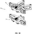
- Fig. 1B illustrates a perspective view of the clamping and breaking system 100.
- the clamping and system 100 can be secured to a mast 110 ( Fig.1A ).
- the clamping device 200 and the breaking device 300 can be moved and/or mounted separately and/or independently. Accordingly, the clamping device 200 and the breaking device 300 can each be positioned as desired to provide a desired amount of separation between the two.
- the clamping device 200 and breaking device 300 can be coupled to other support structure or support structures.
- the support structure or structures can also include a part of any known drilling rig, as the mast 110 ( Fig. 1 ).
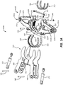
- Fig. 2A illustrates an exploded view of a clamping device 200 according to one example.
- the clamping device 200 includes a housing 205 having an upper portion 205A and a lower portion 205B.
- the upper portion 205A and lower portion 205B are spaced apart by a base mount 210 as well as any number of additional peripheral supports.
- the base mount 210 can allow the clamping device 200 to be secured to a support structure at a desired location to thereby provide a stable platform from which the clamping device 200 can operate.
- the upper portion 205A and the lower portion 205B can have substantially similar configurations. In other examples, the upper portion 205A and the lower portion 205B can have different configurations. For ease of reference, an example will be discussed in which the upper portion 205A and the lower portion 205B have substantially similar configurations. Accordingly, the discussion of the upper portion 205A can be applicable to the lower portion 205B.
- the housing 205 is configured to support one or more of the components of the clamping device 200, including one or more linear actuators, such as clamping cylinders 215, 215'.
- the clamping cylinders 215, 215' are configured to position one or more jaw assemblies 400, 400'.
- the upper portion 205A generally includes opposing arms 225A, 225A'.
- An opening 230 is defined near a central portion of the housing 205 and passes through the upper portion 205A.
- the opening 230 can be sized to allow drill rods or other elongate threaded members of varying diameters to pass through the clamping device 200.
- the clamping cylinders 215, 215' are secured to the housing 205 by outer pins 235, 235'.
- the outer pins 235, 235' can pass through upper portion 205A, through the clamping cylinders 215, 215' and at least partially through the lower portion 205B.
- the outer pins 235, 235' can be secured in place in any suitable manner, such as by a nut, by threaded engagement with one or more of the upper or lower portions 205A, 205B, by lock/snap rings, some combination of these or in any other manner.
- any number of fasteners can be used to secure any number of components described herein. Many of such fasteners have been omitted for clarity in describing the operation of the clamping and breaking system 10 ( Figs. 1A-1B ).
- the clamping cylinders 215, 215' can transfer forces to the jaw assemblies 400, 400' in any manner as they extend and retract.
- channels can be defined between the upper arms 225A, 225A' and lower arms 225B, 225B that are sized to receive and guide the jaw assemblies 400, 400' when the jaw assemblies 400, 400' are moved by extending and retracting the clamping cylinders 215, 215'.
- extension and retraction of the clamping cylinders 215, 215' moves the jaw assemblies 400, 400' into and out of the opening 230.
- the clamping cylinders 215, 215' can exert a force directly onto the jaw assemblies 400, 400' as they extend.
- inner pins 240, 240' can secure the clamping cylinders 215, 215' to the jaw assemblies 400, 400' such that as the clamping cylinders 215, 215' retract, the clamping cylinders 215, 215' move the clamping cylinders 215, 215' relative to the housing 205.
- the clamping device 200 can further include a retention structure, such as a retention strap 242 that is configured to retain a threaded tubular member within the opening 230.
- the retention strap 242 can be removably coupled to the housing 204 with pins 244.
- Moving the jaw assemblies 400, 400' toward and away from the opening 230 can allow the jaw assemblies 400 to engage drill rods or other elongate threaded members of varying diameters as well as to apply a sufficient force to the drill rod to clamp the drill rod.
- Clamping the drill rod can include applying sufficient force to reduce or eliminate rotation of the drill rod relative to the jaw assemblies 400, 400'.
- the jaw assemblies 400, 400' can be substantially similar. In other examples, the jaw assemblies 400, 400' can be configured differently. Further, more or less than two jaw assemblies 400, 400' can be provided as desired.
- the jaw assemblies 400, 400' are configured to be moved into gripping contact with a drill rod to reduce or prevent rotation of the drill rod. Preventing or reducing rotation of one drill rod can allow the breaking device 300 to rotate an additional drill rod on an opposing side of a joint between the two drill rods to break the joint.
- One exemplary breaking device will now be described in more detail.
- Fig. 3A illustrates a top view of a breaking device 300 according to one example.
- the breaking device 300 is configured to clamp a drill rod or other threaded tubular member through actuation of a first set of actuators, such as clamping cylinders, and to break a joint between drill rods or other elongate threaded members through the use of a second set of actuators, such as breaking cylinders.
- a first set of actuators such as clamping cylinders
- the breaking device 300 includes a clamp housing 305 having an upper portion 305A and a lower portion 305B.
- the upper portion 305A and lower portion 305B are spaced apart by any number of peripheral supports.
- the upper portion 305A and the lower portion 305B can have substantially similar configurations.
- the upper portion 305A and the lower portion 305B can have different configurations.
- an example will be discussed in which the upper portion 305A and the lower portion 305B have substantially similar configurations. Accordingly, the discussion of the upper portion 305A can be applicable to the lower portion 305B.
- the clamp housing 305 is configured to support one or more of the components to apply a clamping force to a drill rod, including one actuators, such as clamping cylinders 315, 315'.
- the clamping cylinders 315, 315' are configured to position one or more jaw assemblies 400, 400'.
- the jaw assemblies 400 associated with the breaking device 300 can be substantially similar to the jaw assemblies associated with the clamping device 200 or they can be different.
- the upper portion 305A generally includes opposing arms 325A, 325A'.
- An opening 330 is defined near a central portion of the housing 305 and extends through the upper portion 305A and the lower portion 305B ( Fig. 3B ).
- the opening 330 can be sized to allow drill rods or other elongate threaded members of varying diameters to pass through the clamping device 300.
- the clamping cylinders 315, 315' are secured to the clamp housing 305 by outer pins 335, 335'.
- the outer pins 335, 335' can pass through upper portion 305A, through the clamping cylinders 315, 315' and at least partially through the lower portion 305B.
- the clamping cylinders 215, 215' can transfer forces to the jaw assemblies 400, 400' in any manner as they extend and retract.
- channels can be defined between the upper arms 225A, 225A' and lower arms 225B, 225B that are sized to receive and guide the jaw assemblies 400, 400' when the jaw assemblies 400, 400' are moved by extending and retracting the clamping cylinders 215, 215'.
- extension and retraction of the clamping cylinders 315, 315' moves the jaw assemblies 400 toward and away from the opening 330.
- the breaking device 300 can include a breaking housing 350.
- the breaking housing 350 can generally include an upper portion 350A and a lower portion 350B that are spaced apart by a base mount 352 as well as any number of additional peripheral supports. The separation between the upper portion 350A and the lower portion 350B ( Fig. 3A ) allows the breaking housing 350 to receive at least a portion of the clamping housing 305 therein.
- the clamping housing 305 can be rotatingly coupled to the breaking housing 350 in any manner to allow the breaking housing 350 to rotate the clamping housing 305, which in turn can rotate a drill rod clamped by the jaw assemblies 400, 400'.
- the clamping housing 305 can be coupled to the breaking housing 350 by one or more interfacing bearing rings.
- bearing rings 355, 355' can be associated with outer surfaces of the upper portion 305A and the lower portion 305B of the clamp housing 305 respectively.
- Additional bearing rings 360, 360' can be coupled to inner surfaces of the breaking housing 350.
- spacers 362, 362' can couple the bearing rings 360, 360' to the upper portion 305A and lower portion 305B respectively.
- the bearing rings 355, 355' can have an arcuate shape as well as rims 365, 365 that are positioned on outer portions of the bearing rings 355, 355'.
- Bearing rings 360, 360' can have a shape complimentary to bearing rings 355, 355'. Further, the bearing rings 360, 360' can include rims 370 positioned toward inner portions of the bearing rings 360, 360'. Such a configuration constrains and guides motion of the clamp housing 305 relative to the breaking housing 350 to allow the clamp housing 305 to rotate relative to the break housing 350. In at least one example, bearings or other mechanisms can be employed to reduce friction associated with rotating the clamp housing 305 relative to the breaking housing 350. In other examples, pivots, pins, other rotational devices and/or combinations thereof can be used to allow rotation of the clamp housing 305 relative to the breaking housing 350.
- the clamping cylinders 315 can be actuated to move the jaw assemblies 400, 400' into engagement with one drill rod on one side of a joint while the clamping device 200 ( Figs. 2A-2B ) clamps another drill rod on the other side of the joint.
- the breaking device 300 can rotate the clamp housing 305 with the jaw assemblies 400, 400' thus engaged to break the joint.
- the force exerted by the breaking device 300 when it rotates the drill rod can be absorbed by the breaking arms 380, 380', thereby reducing force and/or vibration transmitted to a support structure.
- the breaking device 300 includes at least one actuator, such as breaking cylinders 375, 375'.
- the breaking cylinders 375, 375' can be coupled to breaking arms 380, 380', which extend away from the base mount 352.
- the breaking cylinders 375, 375' can be coupled to the breaking arms 380, 380' by pins 385, 385' and to clamp housing 305 by pins 390, 390'.
- the breaking arms 380, 380' are positioned such as the breaking cylinders 375, 375' extend and retract they exert a force on the clamping housing 305 to thereby cause the clamp housing 305 to rotate relative to the breaking housing 350 about bearing rings 355, 355' and 360, 360'.
- breaking cylinder 375 As breaking cylinder 375 extends it exerts a force on arms 325A, 325B to cause the clamp housing 305 to rotate. Similarly, breaking cylinder 375' can retract to draw arms 325A', 325B to rotate the same direction. Reversing the extension and retraction of the breaking cylinders 375, 375 can result in rotation of the clamp housing 305 in the opposite direction relative to the breaking housing 350. Accordingly, the breaking device 300 can clamp and rotate a drill rod in two directions, thereby allowing the breaking device 300 to break both right-hand and left-hand joints by deploying actuators, such as actuators. Further, the breaking device 300 can breaking both right-hand and left-hand joints with similar or the same breaking torque. While actuators discussed above have been described as including hydraulic cylinders, it will be appreciated that any type of actuator can be used. For example, linear actuators can include electrically or other solenoids, chain drive systems, gear drive systems, linear actuators or combinations thereof.
- jaw assemblies in general.
- Various types of jaw assemblies can be used to grip and clamp drill rods or other elongate threaded members.
- Exemplary jaw assemblies will be described below that include multiple gripping contacts that are configured to engage elongate threaded members of varying sizes and shapes.
- One exemplary jaw assembly 400 is illustrated in more detail in Figs. 4A-4C .
- Fig. 4A illustrates an exploded view of a jaw assembly 400.
- the jaw assembly 400 generally includes a jaw body 405 having a first end 405A and a second end 405B. While the jaw body 405 is depicted to be substantially rectangular, it will be appreciated that the jaw body can be any shape including round, square, triangular or any other suitable shape to accomplish its function.
- the jaw body 405 can be adapted to reduce or eliminate direct contact between the second end 405B of the jaw body 405 and an engaged threaded tubular member.
- the jaw body 405 can be configured so that the jaw can be advanced and retracted smoothly and stably relative to either the housing 205 of the clamping device and/or the clamp housing 305 of the breaking device 300.
- the jaw body 405 includes insert pockets 410, 410' defined therein.
- the insert pockets 410, 410' are configured to receive inserts 415, 415'.
- the insert pockets 410, 410' can be shaped to allow the inserts 415, 415' to rotate therein.
- the inserts 415, 415' can have an arcuate outer shape.
- the insert pockets 410, 410' can have similar shapes or can be configured differently.
- the inserts 415, 415' are configured to have gripping features, such as tong dies 420 removably coupled thereto.
- the tong dies 420 associated with each of the inserts 415, 415' can be similar or can be different.
- the clamping and breaking devices can securely grip a wide range of pipe (or rod diameters).
- the diameters that can be securely gripped range from about 60 mm to about 350 mm.
- tong dies 420 incorporated in each of the round inserts 415, 415' are in substantially constant contact with the exterior surface of the tubular member during a drilling operation as shown in Fig. 1A .
- This arrangement allows more than four friction contacts, such as eight or more friction contacts, during operation whereas conventional jaw designs, on the other hand, typically only provide four frictional contacts. The increased frictional contact can provide better load transmission, thus increasing capacity and safety while decreasing wear on the associated components.
- the jaw assembly 400 can further include opposing plates 425A, 425B secured to the jaw body 405.
- plate 425A can be coupled to the jaw body 405 by one or more fasteners 430.
- the plates 425A, 425B can be fashioned in such a way that they rarely, if ever, touch a corresponding threaded drill rod directly during operation. Thus, the side plates do not detract from the threading or unthreading action of the jaws. As well, they need not be replaced because they do not wear down from friction with the drill rod.
- Plate 425B can be secured to the opposing side of jaw body 405 in any suitable manner, such as by welding.
- the inserts 415, 415' can be positioned within the insert pockets 410, 410'.
- the arcuate profile of the insert pockets 410, 410' can include shoulders 435, 435'.
- the arcuate profile of the insert pockets 410, 410' can allow the inserts 415, 415' to rotate within the insert pockets 410, 410' while the shoulders 435, 435' can retain the inserts 415, 415' within the insert pockets 410, 410' as will be discussed in more detail below.
- insert 415' can include stop channels 440A', 440B' defined therein.
- the stop channels 440A', 440B' can be configured to engage stops 445A', 445B' that may be passed through openings 450A in the plates 425A, 425B and into engagement one or more stop pocket 452.
- the stops 445A, 445B can also the stop channels 440.
- stops 445A, 445B allow the insert 415' to rotate between engagement with the ends of the stop channels 440A, 440B.
- rotation can be between about 22.5° to about 45°degrees.
- the jaw assembly is configured to allow the inserts 415, 415' to rotate relative to the jaw body 405 while the configuration of the insert pockets 410, 410' helps prevent the insert pockets 410, 410' from inadvertently being dislodged from the jaw body 405.
- the plates 425A and 425B can further help retain the inserts 415, 415' within the jaw assembly 400.
- the use of fasteners 430 to secure the plate 425A to the body 405 can allow plate 425 to be removed to provide access to the inserts, such as to replace the inserts, service the inserts 415, 415' or for other purposes.
- the jaw assembly 400 can include a recess defined in the first end 405A.
- the recess can be formed substantially perpendicular to the first end 405A and substantially parallel to the direction in which the jaw assembly 400 engages the outside surface of the tubular member.
- the recess can be located substantially along the central line of action of the jaw so that a cross pin hole and the pin 240 ( Fig. 2A ) can pass through the recess.
- the recess is configured to receive a piston bar which is advanced and retracted by means of a clamping cylinder as described above.
- the piston bar communicates with the recess such that the front surface of the piston bar contacts jaw body 405, thereby driving the jaw assembly during a clamping operation.
- the piston bar drives the jaw assembly directly and not by means of the cross pin 240.
- the cross pin 240 can help ensure that the jaw assembly 400 is retracted in concert with the piston bar.
- the jaw body 405 is configured to engage threaded tubular members, such as a drill rod 460 illustrated in Fig. 4B .
- a drill rod 460 illustrated in Fig. 4B .
- the inserts 415, 415' pivot relative to the jaw body 405 to move the tong dies 420 into contact with the drill rod 460.
- the jaw body tong dies 420 can rotate to grip drill rods 460 ( Fig. 4B ), 460' ( Fig. 4C ) having a variety of diameters while maximizing the amount of surface area of the tong dies 420 that are in contact with the drill rods.
- the pivoting inserts 415, 415' to maximize the clamping force the jaw assemblies 400, 400' apply to the drill rods 460, 460'. Further, such a configuration can allow operators to use readily available spare parts.
- a jaw assembly 500 can have differently configured inserts 515 and corresponding tong dies interchanged with inserts 515, 515' and tong dies 420.
- the jaw body 505 can be configured to receive round inserts 510 with gripping pads 520.
- various inserts can be provided with accompanying replaceable pads to accommodate any number of angles or configurations. In this manner, the jaw assembly can be capable of gripping a broad range of threaded tubular member diameters as previously discussed.
- inserts 600 can contain a groove 610 and cut 620, so that the gripping pads can be easily removed or clipped out and replaced if a different type of pad or a new pad is desired.
- any type of tong die or gripping pad can be used with inserts including dies and pads that are smooth or incorporate ridges, pads, bumps, teeth and the like to facilitate or alter gripping capacity. Indeed, dies and pads of differing shapes and makes may be used to facilitate or alter gripping capacity.
- round inserts 415 described above include two slots 418, 418' for the tong dies 420, in some embodiments the inserts may accommodate one, three, or even more tong dies as needed. Likewise, while the insets depicted above include one gripping pad, the inserts may accommodate one, two, or even more gripping pads. Further, multiple types of round inserts may be used within the jaw assembly beyond the physical depictions shown above.
- tong dies and gripping pads any types of wear insert can be used with any type of inserts.
- tong dies will be used for certain types of inserts because of the size of the drill rods being gripped.
- gripping pads are used because of the size of the drill rods being gripped.
- the contours of tong dies and gripping pads can be different and, therefore, they can be adapted and used for different purposes.
- the clamping device 200, the breaking device 300, and their components can be constructed out of any suitable material(s) that are structurally sufficient to perform their intended functions.
- suitable material(s) can include but are not limited to steel, aluminum, brass, copper, and other metal alloys .Furthermore, the components can be formed out of any or all of these materials by any method known in the art.
- the clamping and breaking devices may be used in any desired orientation.
- the above description typically refers to a vertical orientation so that they are used on a drill rod that is in a vertical position.
- the devices could be used for a drill rod that is in a horizontal position.
- the devices could be used with any threaded tubular members that are oriented at any angle.
Landscapes
- Engineering & Computer Science (AREA)
- Geology (AREA)
- Mining & Mineral Resources (AREA)
- Life Sciences & Earth Sciences (AREA)
- General Life Sciences & Earth Sciences (AREA)
- Fluid Mechanics (AREA)
- Mechanical Engineering (AREA)
- Environmental & Geological Engineering (AREA)
- Physics & Mathematics (AREA)
- Geochemistry & Mineralogy (AREA)
- Earth Drilling (AREA)
- Automatic Assembly (AREA)
- Clamps And Clips (AREA)
- Details Of Connecting Devices For Male And Female Coupling (AREA)
- Working Measures On Existing Buildindgs (AREA)
Claims (15)
- Klemmbackenanordnung (440), die umfasst:einen Klemmbackenkörper (405) mit einem ersten Ende (405A) und einem zweiten Ende (405B), und wobei der Klemmbackenkörper (405) umfasst:eine Einsatztasche (410), die im Klemmbackenkörper (405) definiert ist, wobei die Einsatztasche (410) umfasst: eine Öffnung an dem ersten Ende (405A) des Klemmbackenkörpers (405); ein bogenförmiges Profil in Bezug auf eine Ebene zwischen dem ersten Ende (405A) und dem zweiten Ende (405B) des Klemmbackenkörpers (405); undeine Schulter (435), die durch einen Abschnitt des ersten Endes (405A) des Klemmbackenkörpers (405) und der Öffnung der Einsatztasche (410) definiert ist; undeinen Einsatz (415), der dazu ausgelegt ist, in der Einsatztasche (410) durch die Schulter des Klemmbackenkörpers (405) gehalten zu werden, wobei der Einsatz (415) dazu ausgelegt ist, in der Einsatztasche (410) zu drehen, und wobei die Schulter (435) dazu ausgelegt ist, den Einsatz (415) in der Einsatztasche (410) zu halten, wobei der Einsatz (415) eine im Wesentlichen teilweise bogenförmige Form, komplementär zum bogenförmigen Profil der zumindest einen Einsatztasche (410), aufweist, und wobei der Einsatz (415) erste und zweite Greifmerkmale (420) aufweist, dadurch gekennzeichnet, dassdie Einsatztasche (410) erste und zweite Anschläge (445A', 445B'), die entlang des bogenförmigen Profils positioniert sind, umfasst, wobei der Einsatz (415) erste und zweite Kanäle (440A', 440B') umfasst, die sich in und entlang der bogenförmigen Form erstrecken, wobei der erste und der zweite Anschlag (440A', 440B') zulassen, dass sich der Einsatz (415) zwischen dem Eingriff in die Enden der ersten und zweiten Kanäle (440A', 440B') dreht, wobei der erste Anschlag (445A') im ersten Kanal (440A') positioniert ist und der zweite Anschlag (445B') im zweiten Kanal (440B') positioniert ist, und dass der Einsatz (415) einen ersten Schlitz (418) und einen zweiten Schlitz (418') umfasst, wobei das erste Greifmerkmal (420) im ersten Schlitz (418) des Einsatzes (415) positioniert ist, und wobei das zweite Greifmerkmal (420) im zweiten Schlitz (418') des Einsatzes (415) positioniert ist.
- Klemmbackenanordnung (400) gemäß Anspruch 1, wobei die Einsatztasche (410) ein teilweise kreisförmiges Profil aufweist.
- Klemmbackenanordnung (400) gemäß Anspruch 1, wobei das erste Greifmerkmal (420) lösbar mit dem ersten Schlitz (418) des Einsatzes (415) gekoppelt ist, und wobei das zweite Greifmerkmal (420) lösbar mit dem zweiten Schlitz (418') des Einsatzes (415) gekoppelt ist.
- Klemmbackenanordnung (400) gemäß Anspruch 1, wobei der erste und der zweite Anschlag (445A', 445B') dazu ausgelegt sind, die Drehung des Einsatzes (415) in Bezug auf die Einsatztasche (410) zu begrenzen.
- Klemmbackenanordnung (400) gemäß Anspruch 4, wobei der erste und der zweite Kanal (440A',440B') dazu ausgelegt sind, mit dem ersten und dem zweiten Anschlag (445A', 445B') zusammenzuwirken, um die Drehung des Einsatzes (415) in Bezug auf die Einsatztasche (410) zu begrenzen.
- Klemmbackenanordnung (400) gemäß Anspruch 4, wobei der erste und der zweite Anschlag (445A', 445B') dazu ausgelegt sind, eine Drehung von 22,5 bis 45 Grad des Einsatzes (415) in Bezug auf den Klemmbackenkörper (405) zuzulassen.
- System (100) zum Klemmen und Brechen von Bohrstrangelementen (140, 140'), das umfasst:eine Klemmvorrichtung (200), die dazu ausgelegt ist, ein Bohrstrangelement (140, 140') zu ergreifen, und die ein Gehäuse (205) und eine mit dem Gehäuse (205) assoziierte Basisbefestigung (210) umfasst; undeine Brechvorrichtung (300), die dazu ausgelegt ist, eine Vorrichtung, die ein Gehäuse und eine mit dem Gehäuse assoziierte Basisbefestigung (352) umfasst, zu ergreifen und zu drehen, wobei die Basisbefestigung (210) der Klemmvorrichtung (200) und die Basisbefestigung (352) der Brechvorrichtung (300) dazu ausgelegt sind, unabhängig voneinander auf zumindest einer Trägerstruktur (110) montiert zu werden, und wobei eine der Klemmvorrichtung (200) und der Brechvorrichtung (300) entgegengesetzte Klemmbackenanordnungen (400, 400') gemäß einem der Ansprüche 1-6 umfasst.
- System (100) gemäß Anspruch 7, wobei die Klemmvorrichtung (200) ferner umfasst:entgegengesetzte Klemmbackenanordnungen (400, 400') gemäß einem der Ansprüche 1-6; undBetätigungsmittel, die dazu ausgelegt sind, die Klemmbackenanordnungen (400, 400') der Klemmvorrichtung (200) in Greifkontakt mit einem Bohrstrangelement (140, 140') zu bringen.
- System (100) gemäß Anspruch 8, wobei die Brechvorrichtung (300) ferner umfasst:ein Klemmgehäuse (305) mit einer Öffnung (330), die darin definiert ist;Klemmbackenanordnungen (400, 400') gemäß einem der Ansprüche 1 - 6;Klemmbetätigungsmittel, die dazu ausgerichtet sind, die Klemmbackenanordnungen (400, 400') mit einem Bohrstrangelement (140, 140') in Eingriff zu bringen; undein Brechgehäuse (350) und Brechbetätigungsmittel, die mit dem Brechgehäuse (350) und dem Klemmgehäuse (305) gekoppelt sind, wobei die Brechbetätigungsmittel dazu ausgelegt sind, das Klemmgehäuse (305) in Bezug auf das Brechgehäuse (350) zu drehen.
- System (100) gemäß Anspruch 9, wobei zumindest eines der Klemmbetätigungsmittel und der Brechbetätigungsmittel einen Brechzylinder (375) umfasst.
- System (100) gemäß Anspruch 9, das ferner komplementäre Lagerringe (355, 360) umfasst, die das Klemmgehäuse (305) an das Brechgehäuse (350) koppeln.
- System (100) gemäß Anspruch 9, wobei das Klemmgehäuse (305) einen oberen Abschnitt (305A) mit entgegengesetzten oberen Armen (325A, 325A') und einen unteren Abschnitt (305B) mit entgegengesetzten unteren Armen (325B, 325B') umfasst, wobei der obere Abschnitt (305A) vom unteren Abschnitt (305B) beabstandet ist.
- System (100) gemäß Anspruch 12, das ferner zumindest einen Kanal zwischen jedem der entgegengesetzten oberen Armen (325A, 325A') und der entgegengesetzten unteren Armen (325B, 325B') umfasst, wobei jeder Kanal dazu ausgelegt ist, eine Klemmbackenanordnung (400, 400') zur Öffnung (330) im Klemmgehäuse (305) hin und davon weg zu führen.
- System (100) gemäß Anspruch 13, wobei die Klemmbetätigungsmittel zwischen den entgegengesetzten oberen Armen (325A, 325A') und den entgegengesetzten unteren Armen (325B, 325B') montiert und ferner mit den Klemmbackenanordnungen (400, 400') gekoppelt sind.
- Klemmbackenanordnung (400) gemäß einem der Ansprüche 1-6, die ferner eine erste Platte (425A) und eine zweite Platte (425B) umfasst, wobei die erste Platte (425A) mit einer ersten Seite des Klemmbackenkörpers (405) gekoppelt ist und die zweite Platte (425B) mit einer zweiten entgegengesetzten Seite des Klemmbackenkörpers (405) gekoppelt ist.
Applications Claiming Priority (3)
| Application Number | Priority Date | Filing Date | Title |
|---|---|---|---|
| US96897007P | 2007-08-30 | 2007-08-30 | |
| US12/197,817 US7997167B2 (en) | 2007-08-30 | 2008-08-25 | Clamping and breaking device |
| PCT/US2008/074499 WO2009032705A1 (en) | 2007-08-30 | 2008-08-27 | Clamping and breaking device |
Publications (3)
| Publication Number | Publication Date |
|---|---|
| EP2183460A1 EP2183460A1 (de) | 2010-05-12 |
| EP2183460A4 EP2183460A4 (de) | 2016-01-20 |
| EP2183460B1 true EP2183460B1 (de) | 2017-11-08 |
Family
ID=40405601
Family Applications (1)
| Application Number | Title | Priority Date | Filing Date |
|---|---|---|---|
| EP08798826.7A Active EP2183460B1 (de) | 2007-08-30 | 2008-08-27 | Klemm- und brechvorrichtung |
Country Status (10)
| Country | Link |
|---|---|
| US (1) | US7997167B2 (de) |
| EP (1) | EP2183460B1 (de) |
| CN (1) | CN101790619B (de) |
| AR (1) | AR068150A1 (de) |
| AU (1) | AU2008296490B2 (de) |
| CA (1) | CA2696269C (de) |
| CL (1) | CL2008002543A1 (de) |
| PE (1) | PE20091609A1 (de) |
| WO (1) | WO2009032705A1 (de) |
| ZA (1) | ZA201000778B (de) |
Families Citing this family (32)
| Publication number | Priority date | Publication date | Assignee | Title |
|---|---|---|---|---|
| US7997166B2 (en) | 2007-06-15 | 2011-08-16 | Longyear Tm, Inc. | Methods and apparatus for joint disassembly |
| US7997167B2 (en) | 2007-08-30 | 2011-08-16 | Longyear Tm, Inc. | Clamping and breaking device |
| EP2274498A2 (de) | 2008-05-12 | 2011-01-19 | Longyear TM, Inc. | Stangenschleuder mit offener oberfläche |
| EP2524105A4 (de) * | 2010-01-15 | 2015-03-04 | Vermeer Mfg Co | Bohrmaschine und -verfahren |
| US20110278515A1 (en) * | 2010-05-14 | 2011-11-17 | Express Energy Services Operating Lp | Pushing or Pulling Device |
| US8286943B2 (en) * | 2010-05-14 | 2012-10-16 | Express Energy Services Operating Lp | Pushing or pulling device |
| KR101828638B1 (ko) * | 2010-08-16 | 2018-03-22 | 티크 마이닝 솔루션스 피티와이 엘티디 | 센트럴라이저 |
| WO2012162617A2 (en) * | 2011-05-26 | 2012-11-29 | Lavalley Industries, Llc | An attachment for making up or breaking out pipe |
| WO2013036140A2 (en) * | 2011-09-09 | 2013-03-14 | National Oilwell Varco Norway As | A die retainer system for a clamp die and method of operation of same |
| US8601911B1 (en) * | 2011-11-22 | 2013-12-10 | Scorpion Oil Tools, Inc. | Tong assembly for manipulating a tubular |
| US9297222B1 (en) * | 2011-11-22 | 2016-03-29 | Scorpion Oil Tools, Inc. | Method for manipulating a tubular |
| US9228399B1 (en) * | 2011-11-22 | 2016-01-05 | Scorpion Oil Tools, Inc. | Tong assembly for manipulating a tubular |
| US9097071B1 (en) * | 2012-03-27 | 2015-08-04 | Scorpion Oil Tools, Inc. | Tong arm assembly with floating jaw |
| US9551194B1 (en) * | 2012-03-27 | 2017-01-24 | Scorpion Oil Tools, Inc. | Tong assembly with floating jaw |
| US9551195B1 (en) * | 2012-03-27 | 2017-01-24 | Scorpion Oil Tools, Inc. | Rig with tong assembly with floating jaw and remote control |
| US9447645B2 (en) | 2012-03-29 | 2016-09-20 | Black Dog Industries Llc | Breakout wrench assemblies and methods |
| PE20160973A1 (es) | 2013-12-30 | 2016-10-06 | Longyear Tm Inc | Sistema de manejo de brocas para mover las brocas hacia y desde una posicion de funcionamiento |
| DE102014208113A1 (de) * | 2014-04-29 | 2015-10-29 | Bentec Gmbh Drilling & Oilfield Systems | Zangensystem zur Verwendung auf einer Bohranlage und Klemmblock eines solchen Zangensystems |
| WO2016179004A1 (en) | 2015-05-01 | 2016-11-10 | Bly Ip Inc. | Drill rod alignment device and systems and methods of using same |
| NO3101218T3 (de) * | 2015-06-05 | 2018-01-06 | ||
| CA3006082A1 (en) | 2015-12-22 | 2017-06-29 | Bly Ip Inc. | Drill rod clamping system and methods of using same |
| AU2017200880B2 (en) * | 2016-02-12 | 2022-01-20 | Joy Global Surface Mining Inc | Mechanism for retaining bits on a blasthole drill |
| CN105649556B (zh) * | 2016-03-21 | 2019-01-08 | 河南龙腾新型钻具制造有限公司 | 一种钻机不停机状态下的钻杆装卸装置 |
| CN105973107B (zh) * | 2016-07-11 | 2018-11-20 | 扬州市双龙工业设备安装有限公司 | 电磁阀阀体螺纹测试机的夹紧定位机构 |
| US10316597B2 (en) * | 2017-03-08 | 2019-06-11 | Forum Us, Inc. | Tubular clamp system |
| CA3103517C (en) * | 2017-08-04 | 2023-01-03 | Bly Ip Inc. | Diamond bodies and tools for gripping drill rods |
| WO2019125698A1 (en) * | 2017-12-19 | 2019-06-27 | Falcon Tools, LLC | Bit breaker technology |
| US11391101B2 (en) | 2017-12-19 | 2022-07-19 | Falcon Tools, LLC | Bit breaker technology |
| CN109403863A (zh) * | 2018-11-02 | 2019-03-01 | 广西业南机械设备有限公司 | 一种半自动钻探取芯设备的行走系统 |
| CN109577884B (zh) * | 2018-12-20 | 2023-11-07 | 江苏徐工工程机械研究院有限公司 | 一种保持块、卸杆结构及使用该结构的深井钻机 |
| CN110552636B (zh) * | 2019-08-20 | 2021-01-26 | 宁夏天地奔牛实业集团有限公司 | 反井钻机锥螺纹安装方法及装置 |
| WO2021195224A1 (en) * | 2020-03-24 | 2021-09-30 | Vacuworx Global Llc | Adaptor block for use with a vacuum material handler |
Family Cites Families (75)
| Publication number | Priority date | Publication date | Assignee | Title |
|---|---|---|---|---|
| US430994A (en) | 1890-06-24 | Pipe-wrench | ||
| US621293A (en) | 1899-03-14 | George f | ||
| US712253A (en) | 1902-08-06 | 1902-10-28 | Joseph D Brown | Chain wrench. |
| US1416685A (en) | 1921-06-30 | 1922-05-23 | J H Williams & Company | Chain pipe wrench |
| US2633045A (en) * | 1949-04-20 | 1953-03-31 | Benjamin L Lurie | Pipe wrench having arm with a recess therein and a pivotally mounted spring-biased pipe-engaging jaw in the recess |
| US2650070A (en) | 1950-04-08 | 1953-08-25 | Byron Jackson Co | Pipe gripping mechanism for power tongs |
| US2921489A (en) | 1957-03-18 | 1960-01-19 | Standard Oil Co | Chain-type pipe wrench |
| US2928301A (en) | 1957-07-18 | 1960-03-15 | Archie W Beeman | Power operated spinning devices for pipe |
| US2933961A (en) | 1957-10-28 | 1960-04-26 | Orville A Adams | Power operated pipe wrench |
| US2989880A (en) | 1958-07-03 | 1961-06-27 | Earl D Hesser | Power tongs |
| GB1451663A (en) | 1973-05-07 | 1976-10-06 | Weatherford Oil Tool | Rotary drive apparatus |
| JPS5135277B2 (de) | 1973-07-30 | 1976-10-01 | ||
| US4076640A (en) * | 1975-02-24 | 1978-02-28 | Xerox Corporation | Preparation of spheroidized particles |
| US4079640A (en) | 1976-10-18 | 1978-03-21 | Golden R L | Pipe make up device |
| US4212212A (en) | 1978-10-06 | 1980-07-15 | Weatherford/Lamb, Inc. | Rotary drive apparatus |
| US4221269A (en) | 1978-12-08 | 1980-09-09 | Hudson Ray E | Pipe spinner |
| US4324157A (en) | 1980-01-28 | 1982-04-13 | Soutsos Michael D | Drill pipe clamp |
| US4475607A (en) * | 1981-12-11 | 1984-10-09 | Walker-Neer Manufacturing Co. Inc. | Clamp and insert for clamping drilling tubulars |
| US4485697A (en) | 1983-04-29 | 1984-12-04 | Foster Cathead Company | Kelly spinner |
| US4683962A (en) | 1983-10-06 | 1987-08-04 | True Martin E | Spinner for use in connecting pipe joints |
| US4512216A (en) | 1984-01-20 | 1985-04-23 | Tommie Rogers | Pipe spinner |
| US4604922A (en) | 1984-09-17 | 1986-08-12 | Soutsos Michael D | Drill pipe turning device |
| US4694712A (en) | 1985-09-26 | 1987-09-22 | Doss Hubert M | Well string section spinning tool |
| JPS62156468A (ja) | 1985-12-27 | 1987-07-11 | 元旦ビューティ工業株式会社 | 屋根の軒先構造 |
| US4765401A (en) | 1986-08-21 | 1988-08-23 | Varco International, Inc. | Apparatus for handling well pipe |
| US4843924A (en) | 1987-09-10 | 1989-07-04 | Hawk Industries, Inc. | Compact high-torque apparatus and method for rotating pipe |
| US4885963A (en) | 1988-02-26 | 1989-12-12 | Mcc Corporation | Oscillating drive apparatus for working tool and working apparatus using the same |
| DE3842081A1 (de) | 1988-03-15 | 1989-09-28 | Hausherr & Soehne Rudolf | Bohrgeraet |
| US4895056A (en) | 1988-11-28 | 1990-01-23 | Weatherford U.S., Inc. | Tong and belt apparatus for a tong |
| JP2652808B2 (ja) | 1989-09-29 | 1997-09-10 | 鉱研工業株式会社 | ダウンザホールドリル掘削装置 |
| US5054550A (en) | 1990-05-24 | 1991-10-08 | W-N Apache Corporation | Centering spinning for down hole tubulars |
| US5060542A (en) * | 1990-10-12 | 1991-10-29 | Hawk Industries, Inc. | Apparatus and method for making and breaking joints in drill pipe strings |
| US5207128A (en) * | 1992-03-23 | 1993-05-04 | Weatherford-Petco, Inc. | Tong with floating jaws |
| US5291808A (en) | 1992-07-08 | 1994-03-08 | Buck David A | Ring gear camming member |
| US5320021A (en) | 1993-02-05 | 1994-06-14 | Heintz Farrell E | Universal chain wrench and tools |
| US5386746A (en) * | 1993-05-26 | 1995-02-07 | Hawk Industries, Inc. | Apparatus for making and breaking joints in drill pipe strings |
| JPH0762968A (ja) | 1993-08-31 | 1995-03-07 | Nippon Soil Kogyo Kk | 管体の着脱装置 |
| US6082225A (en) | 1994-01-31 | 2000-07-04 | Canrig Drilling Technology, Ltd. | Power tong wrench |
| US5660087A (en) | 1995-08-08 | 1997-08-26 | Rae; Donald David | Drill pipe spinner |
| US5845549A (en) * | 1995-12-20 | 1998-12-08 | Frank's Casing Crew And Rental Tools, Inc. | Power tong gripping ring mechanism |
| JPH09250285A (ja) | 1996-03-14 | 1997-09-22 | Koken Boring Mach Co Ltd | 掘削ロッド把持装置 |
| US5931231A (en) | 1996-06-27 | 1999-08-03 | Bucyrus International, Inc. | Blast hole drill pipe gripping mechanism |
| US6050156A (en) | 1996-11-26 | 2000-04-18 | Buck; David A. | Braking mechanism for power tongs |
| AUPO418296A0 (en) | 1996-12-11 | 1997-01-09 | Universal Drilling Systems (Aust) Pty Limited | An apparatus for connecting and disconnecting drill rods |
| AUPO829097A0 (en) | 1997-07-29 | 1997-08-21 | Universal Drilling Systems (Aust) Pty Limited | Apparatus for disconnecting drill rods |
| DE29720465U1 (de) | 1997-11-19 | 1998-01-02 | Hütte & Co Bohrtechnik GmbH, 57462 Olpe | Vorrichtung zum Klemmen und Brechen von Bohrsträngen |
| US6070500A (en) * | 1998-04-20 | 2000-06-06 | White Bear Energy Serives Ltd. | Rotatable die holder |
| WO1999055728A2 (en) | 1998-04-27 | 1999-11-04 | Hsc Research And Development Limited Partnership | Ese genes and proteins |
| AUPP009999A0 (en) | 1999-04-28 | 1999-05-20 | Boart Longyear Pty Ltd | Drill rod handling device |
| US7028585B2 (en) | 1999-11-26 | 2006-04-18 | Weatherford/Lamb, Inc. | Wrenching tong |
| US7861618B2 (en) | 1999-11-26 | 2011-01-04 | Weatherford/Lamb, Inc. | Wrenching tong |
| US6318199B1 (en) | 2000-01-18 | 2001-11-20 | David A. Buck | Load equalizing power tong gear train |
| AU2001273161A1 (en) | 2000-07-06 | 2002-01-21 | Eckel Manufacturing Company, Inc. | High torque power tong |
| JP4684413B2 (ja) | 2000-12-27 | 2011-05-18 | 古河機械金属株式会社 | ロッドのねじ弛め装置 |
| US6935210B2 (en) | 2001-03-19 | 2005-08-30 | Hawk Industries, Inc. | Variable rack adjustment assembly for pipe spinning machines |
| AUPR825501A0 (en) | 2001-10-15 | 2001-11-08 | Udl Kl Pty Ltd | Pipe breaking tool & method |
| JP2003184471A (ja) | 2001-12-20 | 2003-07-03 | Yamamoto Rock Machine Co Ltd | 削孔装置 |
| DE20202396U1 (de) | 2002-02-15 | 2002-06-06 | Prime Drilling GmbH, 57482 Wenden | Klemmvorrichtung für Rundmaterial |
| CA2487120A1 (en) | 2002-05-30 | 2003-12-11 | Gray Eot, Inc. | Drill pipe connecting and disconnecting apparatus |
| CA2440581C (en) * | 2002-09-12 | 2014-04-15 | National-Oilwell, L.P. | Jaw insert for gripping a cylindrical member and method of manufacture |
| US7216724B2 (en) | 2003-06-27 | 2007-05-15 | The Charles Machine Works, Inc. | Coupling for dual member pipe |
| US6910402B2 (en) | 2003-08-13 | 2005-06-28 | National-Oilwell, L. P. | Pipe spinner |
| US7000502B2 (en) | 2003-09-05 | 2006-02-21 | National-Ollwell | Drillpipe spinner |
| US7318491B2 (en) | 2005-04-28 | 2008-01-15 | Astec Industries, Inc. | Apparatus and method for modified horizontal directional drilling assembly |
| US7204173B2 (en) * | 2004-08-06 | 2007-04-17 | Buck David A | Rotatable die tong jaw |
| US20060053977A1 (en) | 2004-09-16 | 2006-03-16 | Hawkins Samuel P Iii | Apparatus and method for assembling and disassembling downhole components in a horizontal mode |
| US20060054331A1 (en) | 2004-09-16 | 2006-03-16 | Hawkins Samuel P Iii | Apparatus and method for making up and breaking out threaded connections of drill bits and bottomhole components |
| CA2551884C (en) | 2005-07-19 | 2009-12-15 | National-Oilwell, L.P. | Single joint drilling system with inclined pipe handling system |
| US7188547B1 (en) | 2005-12-23 | 2007-03-13 | Varco I/P, Inc. | Tubular connect/disconnect apparatus |
| US7191686B1 (en) | 2006-02-01 | 2007-03-20 | Frank's Casing Crew & Rental Tools, Inc. | Method and apparatus for connecting and disconnecting threaded tubulars |
| US7997166B2 (en) | 2007-06-15 | 2011-08-16 | Longyear Tm, Inc. | Methods and apparatus for joint disassembly |
| US7997167B2 (en) | 2007-08-30 | 2011-08-16 | Longyear Tm, Inc. | Clamping and breaking device |
| US7849929B2 (en) | 2008-05-12 | 2010-12-14 | Longyear Tm, Inc. | Drill rod spinner device |
| EP2274498A2 (de) | 2008-05-12 | 2011-01-19 | Longyear TM, Inc. | Stangenschleuder mit offener oberfläche |
| US7975572B2 (en) | 2008-10-02 | 2011-07-12 | Weatherford/Lamb, Inc. | Methods and apparatus for make up and break out of tubular connections |
-
2008
- 2008-08-25 US US12/197,817 patent/US7997167B2/en active Active
- 2008-08-27 WO PCT/US2008/074499 patent/WO2009032705A1/en not_active Ceased
- 2008-08-27 CN CN200880104593.9A patent/CN101790619B/zh not_active Expired - Fee Related
- 2008-08-27 CA CA2696269A patent/CA2696269C/en not_active Expired - Fee Related
- 2008-08-27 EP EP08798826.7A patent/EP2183460B1/de active Active
- 2008-08-27 AU AU2008296490A patent/AU2008296490B2/en active Active
- 2008-08-28 CL CL2008002543A patent/CL2008002543A1/es unknown
- 2008-08-29 PE PE2008001469A patent/PE20091609A1/es not_active Application Discontinuation
- 2008-08-29 AR ARP080103787A patent/AR068150A1/es unknown
-
2010
- 2010-02-02 ZA ZA2010/00778A patent/ZA201000778B/en unknown
Non-Patent Citations (1)
| Title |
|---|
| None * |
Also Published As
| Publication number | Publication date |
|---|---|
| WO2009032705A1 (en) | 2009-03-12 |
| CA2696269C (en) | 2012-12-04 |
| AU2008296490A1 (en) | 2009-03-12 |
| US7997167B2 (en) | 2011-08-16 |
| CA2696269A1 (en) | 2009-03-12 |
| ZA201000778B (en) | 2011-04-28 |
| CN101790619B (zh) | 2014-05-28 |
| CL2008002543A1 (es) | 2009-12-28 |
| EP2183460A4 (de) | 2016-01-20 |
| US20090056931A1 (en) | 2009-03-05 |
| AR068150A1 (es) | 2009-11-04 |
| AU2008296490B2 (en) | 2011-06-09 |
| PE20091609A1 (es) | 2009-11-04 |
| CN101790619A (zh) | 2010-07-28 |
| EP2183460A1 (de) | 2010-05-12 |
Similar Documents
| Publication | Publication Date | Title |
|---|---|---|
| EP2183460B1 (de) | Klemm- und brechvorrichtung | |
| US9144894B2 (en) | Drill pipe breakout machine | |
| EP2115264B1 (de) | Bohrstammführung und schlüsselvorrichtung | |
| US7707914B2 (en) | Apparatus and methods for connecting tubulars | |
| EP3218570B1 (de) | Befestigung zum reparieren oder herausbrechen eines rohrs | |
| EP1212172B1 (de) | Angetriebene zange mit geschlossenem kopf | |
| EP3630414B1 (de) | Schraubenschlüsselanordnung mit schwimmenden drehmomentkörpern | |
| US8454066B2 (en) | Grip extension linkage to provide gripping tool with improved operational range, and method of use of the same | |
| US20070068669A1 (en) | Pipe gripping ram | |
| US10006260B2 (en) | Power tong spool valve speed limiting system | |
| US20090272233A1 (en) | Tong Unit Having Multi-Jaw Assembly Gripping System | |
| US7204173B2 (en) | Rotatable die tong jaw | |
| US11396780B2 (en) | Wrench for use with making and breaking a drill string | |
| EP3631146B1 (de) | Schraubenmontage mit rohrzentriervorrichtung | |
| WO1999006186A1 (en) | Apparatus for disconnecting drill rods | |
| EP3348782B1 (de) | Vorrichtung und verfahren zum greifen eines rohrförmigen elements | |
| US20220268112A1 (en) | Ergonomic shoe interface system for core drilling | |
| EP0166675B1 (de) | Zange und Zangenanordnung | |
| CA3149725A1 (en) | Ergonomic shoe interface system for core drilling | |
| CA3068024C (en) | Wrench for use with making and breaking a drill string | |
| CN105102755A (zh) | 可更换模具 |
Legal Events
| Date | Code | Title | Description |
|---|---|---|---|
| PUAI | Public reference made under article 153(3) epc to a published international application that has entered the european phase |
Free format text: ORIGINAL CODE: 0009012 |
|
| 17P | Request for examination filed |
Effective date: 20100222 |
|
| AK | Designated contracting states |
Kind code of ref document: A1 Designated state(s): AT BE BG CH CY CZ DE DK EE ES FI FR GB GR HR HU IE IS IT LI LT LU LV MC MT NL NO PL PT RO SE SI SK TR |
|
| AX | Request for extension of the european patent |
Extension state: AL BA MK RS |
|
| DAX | Request for extension of the european patent (deleted) | ||
| RA4 | Supplementary search report drawn up and despatched (corrected) |
Effective date: 20151218 |
|
| RIC1 | Information provided on ipc code assigned before grant |
Ipc: E21B 19/16 20060101ALI20151214BHEP Ipc: E21B 19/24 20060101ALI20151214BHEP Ipc: E21B 19/06 20060101AFI20151214BHEP |
|
| 17Q | First examination report despatched |
Effective date: 20161019 |
|
| GRAP | Despatch of communication of intention to grant a patent |
Free format text: ORIGINAL CODE: EPIDOSNIGR1 |
|
| INTG | Intention to grant announced |
Effective date: 20170621 |
|
| GRAS | Grant fee paid |
Free format text: ORIGINAL CODE: EPIDOSNIGR3 |
|
| GRAA | (expected) grant |
Free format text: ORIGINAL CODE: 0009210 |
|
| AK | Designated contracting states |
Kind code of ref document: B1 Designated state(s): AT BE BG CH CY CZ DE DK EE ES FI FR GB GR HR HU IE IS IT LI LT LU LV MC MT NL NO PL PT RO SE SI SK TR |
|
| REG | Reference to a national code |
Ref country code: GB Ref legal event code: FG4D |
|
| REG | Reference to a national code |
Ref country code: CH Ref legal event code: EP Ref country code: AT Ref legal event code: REF Ref document number: 944339 Country of ref document: AT Kind code of ref document: T Effective date: 20171115 |
|
| REG | Reference to a national code |
Ref country code: IE Ref legal event code: FG4D |
|
| REG | Reference to a national code |
Ref country code: DE Ref legal event code: R096 Ref document number: 602008052882 Country of ref document: DE |
|
| REG | Reference to a national code |
Ref country code: NL Ref legal event code: MP Effective date: 20171108 |
|
| REG | Reference to a national code |
Ref country code: LT Ref legal event code: MG4D |
|
| REG | Reference to a national code |
Ref country code: AT Ref legal event code: MK05 Ref document number: 944339 Country of ref document: AT Kind code of ref document: T Effective date: 20171108 |
|
| PG25 | Lapsed in a contracting state [announced via postgrant information from national office to epo] |
Ref country code: LT Free format text: LAPSE BECAUSE OF FAILURE TO SUBMIT A TRANSLATION OF THE DESCRIPTION OR TO PAY THE FEE WITHIN THE PRESCRIBED TIME-LIMIT Effective date: 20171108 Ref country code: SE Free format text: LAPSE BECAUSE OF FAILURE TO SUBMIT A TRANSLATION OF THE DESCRIPTION OR TO PAY THE FEE WITHIN THE PRESCRIBED TIME-LIMIT Effective date: 20171108 Ref country code: NL Free format text: LAPSE BECAUSE OF FAILURE TO SUBMIT A TRANSLATION OF THE DESCRIPTION OR TO PAY THE FEE WITHIN THE PRESCRIBED TIME-LIMIT Effective date: 20171108 Ref country code: NO Free format text: LAPSE BECAUSE OF FAILURE TO SUBMIT A TRANSLATION OF THE DESCRIPTION OR TO PAY THE FEE WITHIN THE PRESCRIBED TIME-LIMIT Effective date: 20180208 Ref country code: ES Free format text: LAPSE BECAUSE OF FAILURE TO SUBMIT A TRANSLATION OF THE DESCRIPTION OR TO PAY THE FEE WITHIN THE PRESCRIBED TIME-LIMIT Effective date: 20171108 Ref country code: FI Free format text: LAPSE BECAUSE OF FAILURE TO SUBMIT A TRANSLATION OF THE DESCRIPTION OR TO PAY THE FEE WITHIN THE PRESCRIBED TIME-LIMIT Effective date: 20171108 |
|
| PG25 | Lapsed in a contracting state [announced via postgrant information from national office to epo] |
Ref country code: IS Free format text: LAPSE BECAUSE OF FAILURE TO SUBMIT A TRANSLATION OF THE DESCRIPTION OR TO PAY THE FEE WITHIN THE PRESCRIBED TIME-LIMIT Effective date: 20180308 Ref country code: GR Free format text: LAPSE BECAUSE OF FAILURE TO SUBMIT A TRANSLATION OF THE DESCRIPTION OR TO PAY THE FEE WITHIN THE PRESCRIBED TIME-LIMIT Effective date: 20180209 Ref country code: HR Free format text: LAPSE BECAUSE OF FAILURE TO SUBMIT A TRANSLATION OF THE DESCRIPTION OR TO PAY THE FEE WITHIN THE PRESCRIBED TIME-LIMIT Effective date: 20171108 Ref country code: BG Free format text: LAPSE BECAUSE OF FAILURE TO SUBMIT A TRANSLATION OF THE DESCRIPTION OR TO PAY THE FEE WITHIN THE PRESCRIBED TIME-LIMIT Effective date: 20180208 Ref country code: LV Free format text: LAPSE BECAUSE OF FAILURE TO SUBMIT A TRANSLATION OF THE DESCRIPTION OR TO PAY THE FEE WITHIN THE PRESCRIBED TIME-LIMIT Effective date: 20171108 Ref country code: AT Free format text: LAPSE BECAUSE OF FAILURE TO SUBMIT A TRANSLATION OF THE DESCRIPTION OR TO PAY THE FEE WITHIN THE PRESCRIBED TIME-LIMIT Effective date: 20171108 |
|
| REG | Reference to a national code |
Ref country code: FR Ref legal event code: PLFP Year of fee payment: 11 |
|
| PG25 | Lapsed in a contracting state [announced via postgrant information from national office to epo] |
Ref country code: CZ Free format text: LAPSE BECAUSE OF FAILURE TO SUBMIT A TRANSLATION OF THE DESCRIPTION OR TO PAY THE FEE WITHIN THE PRESCRIBED TIME-LIMIT Effective date: 20171108 Ref country code: SK Free format text: LAPSE BECAUSE OF FAILURE TO SUBMIT A TRANSLATION OF THE DESCRIPTION OR TO PAY THE FEE WITHIN THE PRESCRIBED TIME-LIMIT Effective date: 20171108 Ref country code: CY Free format text: LAPSE BECAUSE OF FAILURE TO SUBMIT A TRANSLATION OF THE DESCRIPTION OR TO PAY THE FEE WITHIN THE PRESCRIBED TIME-LIMIT Effective date: 20171108 Ref country code: DK Free format text: LAPSE BECAUSE OF FAILURE TO SUBMIT A TRANSLATION OF THE DESCRIPTION OR TO PAY THE FEE WITHIN THE PRESCRIBED TIME-LIMIT Effective date: 20171108 Ref country code: EE Free format text: LAPSE BECAUSE OF FAILURE TO SUBMIT A TRANSLATION OF THE DESCRIPTION OR TO PAY THE FEE WITHIN THE PRESCRIBED TIME-LIMIT Effective date: 20171108 |
|
| REG | Reference to a national code |
Ref country code: DE Ref legal event code: R097 Ref document number: 602008052882 Country of ref document: DE |
|
| PG25 | Lapsed in a contracting state [announced via postgrant information from national office to epo] |
Ref country code: RO Free format text: LAPSE BECAUSE OF FAILURE TO SUBMIT A TRANSLATION OF THE DESCRIPTION OR TO PAY THE FEE WITHIN THE PRESCRIBED TIME-LIMIT Effective date: 20171108 Ref country code: PL Free format text: LAPSE BECAUSE OF FAILURE TO SUBMIT A TRANSLATION OF THE DESCRIPTION OR TO PAY THE FEE WITHIN THE PRESCRIBED TIME-LIMIT Effective date: 20171108 |
|
| PLBE | No opposition filed within time limit |
Free format text: ORIGINAL CODE: 0009261 |
|
| STAA | Information on the status of an ep patent application or granted ep patent |
Free format text: STATUS: NO OPPOSITION FILED WITHIN TIME LIMIT |
|
| 26N | No opposition filed |
Effective date: 20180809 |
|
| PG25 | Lapsed in a contracting state [announced via postgrant information from national office to epo] |
Ref country code: SI Free format text: LAPSE BECAUSE OF FAILURE TO SUBMIT A TRANSLATION OF THE DESCRIPTION OR TO PAY THE FEE WITHIN THE PRESCRIBED TIME-LIMIT Effective date: 20171108 |
|
| PG25 | Lapsed in a contracting state [announced via postgrant information from national office to epo] |
Ref country code: MC Free format text: LAPSE BECAUSE OF FAILURE TO SUBMIT A TRANSLATION OF THE DESCRIPTION OR TO PAY THE FEE WITHIN THE PRESCRIBED TIME-LIMIT Effective date: 20171108 |
|
| REG | Reference to a national code |
Ref country code: CH Ref legal event code: PL |
|
| GBPC | Gb: european patent ceased through non-payment of renewal fee |
Effective date: 20180827 |
|
| PG25 | Lapsed in a contracting state [announced via postgrant information from national office to epo] |
Ref country code: LU Free format text: LAPSE BECAUSE OF NON-PAYMENT OF DUE FEES Effective date: 20180827 Ref country code: CH Free format text: LAPSE BECAUSE OF NON-PAYMENT OF DUE FEES Effective date: 20180831 Ref country code: LI Free format text: LAPSE BECAUSE OF NON-PAYMENT OF DUE FEES Effective date: 20180831 |
|
| REG | Reference to a national code |
Ref country code: BE Ref legal event code: MM Effective date: 20180831 |
|
| PG25 | Lapsed in a contracting state [announced via postgrant information from national office to epo] |
Ref country code: BE Free format text: LAPSE BECAUSE OF NON-PAYMENT OF DUE FEES Effective date: 20180831 |
|
| PG25 | Lapsed in a contracting state [announced via postgrant information from national office to epo] |
Ref country code: GB Free format text: LAPSE BECAUSE OF NON-PAYMENT OF DUE FEES Effective date: 20180827 |
|
| PGFP | Annual fee paid to national office [announced via postgrant information from national office to epo] |
Ref country code: DE Payment date: 20190715 Year of fee payment: 12 |
|
| PG25 | Lapsed in a contracting state [announced via postgrant information from national office to epo] |
Ref country code: MT Free format text: LAPSE BECAUSE OF NON-PAYMENT OF DUE FEES Effective date: 20180827 |
|
| PG25 | Lapsed in a contracting state [announced via postgrant information from national office to epo] |
Ref country code: TR Free format text: LAPSE BECAUSE OF FAILURE TO SUBMIT A TRANSLATION OF THE DESCRIPTION OR TO PAY THE FEE WITHIN THE PRESCRIBED TIME-LIMIT Effective date: 20171108 |
|
| PG25 | Lapsed in a contracting state [announced via postgrant information from national office to epo] |
Ref country code: PT Free format text: LAPSE BECAUSE OF FAILURE TO SUBMIT A TRANSLATION OF THE DESCRIPTION OR TO PAY THE FEE WITHIN THE PRESCRIBED TIME-LIMIT Effective date: 20171108 Ref country code: HU Free format text: LAPSE BECAUSE OF FAILURE TO SUBMIT A TRANSLATION OF THE DESCRIPTION OR TO PAY THE FEE WITHIN THE PRESCRIBED TIME-LIMIT; INVALID AB INITIO Effective date: 20080827 |
|
| PG25 | Lapsed in a contracting state [announced via postgrant information from national office to epo] |
Ref country code: IE Free format text: LAPSE BECAUSE OF NON-PAYMENT OF DUE FEES Effective date: 20180827 |
|
| REG | Reference to a national code |
Ref country code: DE Ref legal event code: R119 Ref document number: 602008052882 Country of ref document: DE |
|
| PG25 | Lapsed in a contracting state [announced via postgrant information from national office to epo] |
Ref country code: DE Free format text: LAPSE BECAUSE OF NON-PAYMENT OF DUE FEES Effective date: 20210302 |
|
| P01 | Opt-out of the competence of the unified patent court (upc) registered |
Effective date: 20230523 |
|
| PGFP | Annual fee paid to national office [announced via postgrant information from national office to epo] |
Ref country code: IT Payment date: 20250811 Year of fee payment: 18 |
|
| PGFP | Annual fee paid to national office [announced via postgrant information from national office to epo] |
Ref country code: FR Payment date: 20250709 Year of fee payment: 18 |