EP2183477B1 - Procede d'injection de carburant dans la chambre de combustion d'un moteur a combustion interne - Google Patents
Procede d'injection de carburant dans la chambre de combustion d'un moteur a combustion interne Download PDFInfo
- Publication number
- EP2183477B1 EP2183477B1 EP08782821A EP08782821A EP2183477B1 EP 2183477 B1 EP2183477 B1 EP 2183477B1 EP 08782821 A EP08782821 A EP 08782821A EP 08782821 A EP08782821 A EP 08782821A EP 2183477 B1 EP2183477 B1 EP 2183477B1
- Authority
- EP
- European Patent Office
- Prior art keywords
- fuel
- flushing
- pressure
- pump
- flushing volume
- Prior art date
- Legal status (The legal status is an assumption and is not a legal conclusion. Google has not performed a legal analysis and makes no representation as to the accuracy of the status listed.)
- Not-in-force
Links
- 239000000446 fuel Substances 0.000 title claims description 47
- 238000002485 combustion reaction Methods 0.000 title claims description 15
- 238000000034 method Methods 0.000 title claims description 13
- 238000011010 flushing procedure Methods 0.000 claims description 30
- 238000002347 injection Methods 0.000 claims description 21
- 239000007924 injection Substances 0.000 claims description 21
- 238000001816 cooling Methods 0.000 description 11
- 238000010926 purge Methods 0.000 description 10
- 238000010438 heat treatment Methods 0.000 description 4
- 239000000295 fuel oil Substances 0.000 description 3
- 230000006835 compression Effects 0.000 description 2
- 238000007906 compression Methods 0.000 description 2
- 230000001276 controlling effect Effects 0.000 description 2
- 230000001419 dependent effect Effects 0.000 description 1
- 238000011161 development Methods 0.000 description 1
- 230000018109 developmental process Effects 0.000 description 1
- 239000002828 fuel tank Substances 0.000 description 1
- 239000010687 lubricating oil Substances 0.000 description 1
- 239000000463 material Substances 0.000 description 1
- 238000002156 mixing Methods 0.000 description 1
- 239000000203 mixture Substances 0.000 description 1
- 239000010705 motor oil Substances 0.000 description 1
- 230000037452 priming Effects 0.000 description 1
- 230000001105 regulatory effect Effects 0.000 description 1
- 239000007787 solid Substances 0.000 description 1
- 230000003685 thermal hair damage Effects 0.000 description 1
Images


Classifications
-
- F—MECHANICAL ENGINEERING; LIGHTING; HEATING; WEAPONS; BLASTING
- F02—COMBUSTION ENGINES; HOT-GAS OR COMBUSTION-PRODUCT ENGINE PLANTS
- F02M—SUPPLYING COMBUSTION ENGINES IN GENERAL WITH COMBUSTIBLE MIXTURES OR CONSTITUENTS THEREOF
- F02M61/00—Fuel-injectors not provided for in groups F02M39/00 - F02M57/00 or F02M67/00
- F02M61/16—Details not provided for in, or of interest apart from, the apparatus of groups F02M61/02 - F02M61/14
- F02M61/168—Assembling; Disassembling; Manufacturing; Adjusting
-
- F—MECHANICAL ENGINEERING; LIGHTING; HEATING; WEAPONS; BLASTING
- F02—COMBUSTION ENGINES; HOT-GAS OR COMBUSTION-PRODUCT ENGINE PLANTS
- F02M—SUPPLYING COMBUSTION ENGINES IN GENERAL WITH COMBUSTIBLE MIXTURES OR CONSTITUENTS THEREOF
- F02M47/00—Fuel-injection apparatus operated cyclically with fuel-injection valves actuated by fluid pressure
- F02M47/02—Fuel-injection apparatus operated cyclically with fuel-injection valves actuated by fluid pressure of accumulator-injector type, i.e. having fuel pressure of accumulator tending to open, and fuel pressure in other chamber tending to close, injection valves and having means for periodically releasing that closing pressure
- F02M47/027—Electrically actuated valves draining the chamber to release the closing pressure
-
- B—PERFORMING OPERATIONS; TRANSPORTING
- B05—SPRAYING OR ATOMISING IN GENERAL; APPLYING FLUENT MATERIALS TO SURFACES, IN GENERAL
- B05B—SPRAYING APPARATUS; ATOMISING APPARATUS; NOZZLES
- B05B9/00—Spraying apparatus for discharge of liquids or other fluent material, without essentially mixing with gas or vapour
- B05B9/002—Spraying apparatus for discharge of liquids or other fluent material, without essentially mixing with gas or vapour incorporating means for heating or cooling, e.g. the material to be sprayed
-
- F—MECHANICAL ENGINEERING; LIGHTING; HEATING; WEAPONS; BLASTING
- F02—COMBUSTION ENGINES; HOT-GAS OR COMBUSTION-PRODUCT ENGINE PLANTS
- F02M—SUPPLYING COMBUSTION ENGINES IN GENERAL WITH COMBUSTIBLE MIXTURES OR CONSTITUENTS THEREOF
- F02M51/00—Fuel-injection apparatus characterised by being operated electrically
- F02M51/06—Injectors peculiar thereto with means directly operating the valve needle
- F02M51/061—Injectors peculiar thereto with means directly operating the valve needle using electromagnetic operating means
- F02M51/0625—Injectors peculiar thereto with means directly operating the valve needle using electromagnetic operating means characterised by arrangement of mobile armatures
- F02M51/0664—Injectors peculiar thereto with means directly operating the valve needle using electromagnetic operating means characterised by arrangement of mobile armatures having a cylindrically or partly cylindrically shaped armature, e.g. entering the winding; having a plate-shaped or undulated armature entering the winding
- F02M51/0667—Injectors peculiar thereto with means directly operating the valve needle using electromagnetic operating means characterised by arrangement of mobile armatures having a cylindrically or partly cylindrically shaped armature, e.g. entering the winding; having a plate-shaped or undulated armature entering the winding the armature acting as a valve or having a short valve body attached thereto
-
- F—MECHANICAL ENGINEERING; LIGHTING; HEATING; WEAPONS; BLASTING
- F02—COMBUSTION ENGINES; HOT-GAS OR COMBUSTION-PRODUCT ENGINE PLANTS
- F02M—SUPPLYING COMBUSTION ENGINES IN GENERAL WITH COMBUSTIBLE MIXTURES OR CONSTITUENTS THEREOF
- F02M53/00—Fuel-injection apparatus characterised by having heating, cooling or thermally-insulating means
- F02M53/04—Injectors with heating, cooling, or thermally-insulating means
- F02M53/043—Injectors with heating, cooling, or thermally-insulating means with cooling means other than air cooling
-
- F—MECHANICAL ENGINEERING; LIGHTING; HEATING; WEAPONS; BLASTING
- F02—COMBUSTION ENGINES; HOT-GAS OR COMBUSTION-PRODUCT ENGINE PLANTS
- F02M—SUPPLYING COMBUSTION ENGINES IN GENERAL WITH COMBUSTIBLE MIXTURES OR CONSTITUENTS THEREOF
- F02M53/00—Fuel-injection apparatus characterised by having heating, cooling or thermally-insulating means
- F02M53/04—Injectors with heating, cooling, or thermally-insulating means
- F02M53/06—Injectors with heating, cooling, or thermally-insulating means with fuel-heating means, e.g. for vaporising
-
- F—MECHANICAL ENGINEERING; LIGHTING; HEATING; WEAPONS; BLASTING
- F02—COMBUSTION ENGINES; HOT-GAS OR COMBUSTION-PRODUCT ENGINE PLANTS
- F02M—SUPPLYING COMBUSTION ENGINES IN GENERAL WITH COMBUSTIBLE MIXTURES OR CONSTITUENTS THEREOF
- F02M57/00—Fuel-injectors combined or associated with other devices
- F02M57/02—Injectors structurally combined with fuel-injection pumps
- F02M57/022—Injectors structurally combined with fuel-injection pumps characterised by the pump drive
- F02M57/025—Injectors structurally combined with fuel-injection pumps characterised by the pump drive hydraulic, e.g. with pressure amplification
-
- F—MECHANICAL ENGINEERING; LIGHTING; HEATING; WEAPONS; BLASTING
- F02—COMBUSTION ENGINES; HOT-GAS OR COMBUSTION-PRODUCT ENGINE PLANTS
- F02M—SUPPLYING COMBUSTION ENGINES IN GENERAL WITH COMBUSTIBLE MIXTURES OR CONSTITUENTS THEREOF
- F02M59/00—Pumps specially adapted for fuel-injection and not provided for in groups F02M39/00 -F02M57/00, e.g. rotary cylinder-block type of pumps
- F02M59/20—Varying fuel delivery in quantity or timing
- F02M59/36—Varying fuel delivery in quantity or timing by variably-timed valves controlling fuel passages to pumping elements or overflow passages
- F02M59/366—Valves being actuated electrically
-
- F—MECHANICAL ENGINEERING; LIGHTING; HEATING; WEAPONS; BLASTING
- F02—COMBUSTION ENGINES; HOT-GAS OR COMBUSTION-PRODUCT ENGINE PLANTS
- F02M—SUPPLYING COMBUSTION ENGINES IN GENERAL WITH COMBUSTIBLE MIXTURES OR CONSTITUENTS THEREOF
- F02M61/00—Fuel-injectors not provided for in groups F02M39/00 - F02M57/00 or F02M67/00
- F02M61/04—Fuel-injectors not provided for in groups F02M39/00 - F02M57/00 or F02M67/00 having valves, e.g. having a plurality of valves in series
- F02M61/10—Other injectors with elongated valve bodies, i.e. of needle-valve type
-
- F—MECHANICAL ENGINEERING; LIGHTING; HEATING; WEAPONS; BLASTING
- F23—COMBUSTION APPARATUS; COMBUSTION PROCESSES
- F23D—BURNERS
- F23D11/00—Burners using a direct spraying action of liquid droplets or vaporised liquid into the combustion space
- F23D11/24—Burners using a direct spraying action of liquid droplets or vaporised liquid into the combustion space by pressurisation of the fuel before a nozzle through which it is sprayed by a substantial pressure reduction into a space
- F23D11/26—Burners using a direct spraying action of liquid droplets or vaporised liquid into the combustion space by pressurisation of the fuel before a nozzle through which it is sprayed by a substantial pressure reduction into a space with provision for varying the rate at which the fuel is sprayed
- F23D11/28—Burners using a direct spraying action of liquid droplets or vaporised liquid into the combustion space by pressurisation of the fuel before a nozzle through which it is sprayed by a substantial pressure reduction into a space with provision for varying the rate at which the fuel is sprayed with flow-back of fuel at the burner, e.g. using by-pass
-
- F—MECHANICAL ENGINEERING; LIGHTING; HEATING; WEAPONS; BLASTING
- F02—COMBUSTION ENGINES; HOT-GAS OR COMBUSTION-PRODUCT ENGINE PLANTS
- F02M—SUPPLYING COMBUSTION ENGINES IN GENERAL WITH COMBUSTIBLE MIXTURES OR CONSTITUENTS THEREOF
- F02M2547/00—Special features for fuel-injection valves actuated by fluid pressure
- F02M2547/001—Control chambers formed by movable sleeves
-
- F—MECHANICAL ENGINEERING; LIGHTING; HEATING; WEAPONS; BLASTING
- F02—COMBUSTION ENGINES; HOT-GAS OR COMBUSTION-PRODUCT ENGINE PLANTS
- F02M—SUPPLYING COMBUSTION ENGINES IN GENERAL WITH COMBUSTIBLE MIXTURES OR CONSTITUENTS THEREOF
- F02M2700/00—Supplying, feeding or preparing air, fuel, fuel air mixtures or auxiliary fluids for a combustion engine; Use of exhaust gas; Compressors for piston engines
- F02M2700/07—Nozzles and injectors with controllable fuel supply
- F02M2700/077—Injectors having cooling or heating means
-
- F—MECHANICAL ENGINEERING; LIGHTING; HEATING; WEAPONS; BLASTING
- F02—COMBUSTION ENGINES; HOT-GAS OR COMBUSTION-PRODUCT ENGINE PLANTS
- F02M—SUPPLYING COMBUSTION ENGINES IN GENERAL WITH COMBUSTIBLE MIXTURES OR CONSTITUENTS THEREOF
- F02M31/00—Apparatus for thermally treating combustion-air, fuel, or fuel-air mixture
- F02M31/20—Apparatus for thermally treating combustion-air, fuel, or fuel-air mixture for cooling
-
- F—MECHANICAL ENGINEERING; LIGHTING; HEATING; WEAPONS; BLASTING
- F02—COMBUSTION ENGINES; HOT-GAS OR COMBUSTION-PRODUCT ENGINE PLANTS
- F02M—SUPPLYING COMBUSTION ENGINES IN GENERAL WITH COMBUSTIBLE MIXTURES OR CONSTITUENTS THEREOF
- F02M63/00—Other fuel-injection apparatus having pertinent characteristics not provided for in groups F02M39/00 - F02M57/00 or F02M67/00; Details, component parts, or accessories of fuel-injection apparatus, not provided for in, or of interest apart from, the apparatus of groups F02M39/00 - F02M61/00 or F02M67/00; Combination of fuel pump with other devices, e.g. lubricating oil pump
- F02M63/0012—Valves
- F02M63/0014—Valves characterised by the valve actuating means
- F02M63/0015—Valves characterised by the valve actuating means electrical, e.g. using solenoid
Definitions
- the present invention relates to a method for injecting fuel into the combustion chamber of an internal combustion engine, in which the fuel is conveyed from a prefeed pump from a tank to a high pressure pump and the high pressure pumped by the high pressure pump high pressure fuel is supplied to the injection injector, wherein the injector injector with a having axially displaceable nozzle needle, which dips into a fuel-pressurized control chamber, the pressure of which is controlled via a at least one inlet or outlet channel for fuel opening or closing control valve, and a device for injecting fuel into the combustion chamber of an internal combustion engine.
- Injection injectors of the type described above are often used in common rail injection systems.
- Injectors for common rail systems for injecting high viscosity fuels into the combustion chamber of internal combustion engines are known in various forms. In the case of heavy oil, heating up to 150 ° C is required to achieve the necessary injection viscosity. With a high proportion of abrasive solids and a high temperature naturally increases the Veschl employ and thus affects the reliability.
- an injector for a common rail injection system has different parts, which are usually held together by a nozzle retaining nut.
- the actual injector nozzle contains a nozzle needle, which is guided axially displaceably in the nozzle body of the injector nozzle and has a plurality of open spaces through which fuel can flow from the nozzle antechamber to the needle tip.
- the nozzle needle itself carries a collar on which a compression spring is supported, and dives into a control room, which can be acted upon with fuel under pressure.
- An inlet channel can be connected to this control chamber via an inlet throttle and an outlet channel via an outlet throttle, wherein the respective pressure built up in the control chamber together with the force of the compression spring holds the nozzle needle in the closed position.
- the pressure in the control chamber can be controlled by a control valve, which is usually operated by an electromagnet.
- a control valve which is usually operated by an electromagnet.
- an opening of the solenoid valve can cause a flow of fuel through a throttle, so that a decrease in the hydraulic holding force leads to the immersed into the control chamber end face of the nozzle needle for opening the nozzle needle. In this way, the fuel can pass through the injection openings in the combustion chamber of the engine in the sequence.
- an inlet throttle is usually also provided, wherein the opening speed of the nozzle needle is determined by the flow difference between the inlet and outlet throttle.
- a temperature control or cooling of injection injectors is for example from the WO 2006/021014 A1 known, are arranged in the injector by additional perfused by lubricating oil or engine oil channels for the purpose of cooling.
- the invention now aims to improve the method for injecting fuel into the combustion chamber of an internal combustion engine of the type mentioned in that improved cooling of the control valve, in particular solenoid valve is achieved.
- the invention essentially proceeds in such a way that a subset of the fuel is diverted as Spülmenge between the prefeed pump and the high-pressure pump and a purge passage of the injection injector is supplied, wherein the purge is fed directly to the control valve, so that the purge flow through the control valve at least partially and preferably mixed with the fuel from the inlet and outlet channel, and that the flushing amount is passed through a heat exchanger for controlling the temperature of the flushing.
- the procedure according to the invention it is possible to carry out effective cooling of the solenoid valve without complex internals, wherein already the removal of a small amount of fuel between priming pump and high-pressure pump is sufficient to achieve a significant reduction of the temperature in the region of the solenoid valve.
- the flushing quantity is in this case conducted via a heat exchanger for preheating the flushing quantity.
- the cooling capacity can be adjusted, wherein the temperature comprises the cooling of the flushing amount.
- a heating of the valve for example, before the engine start, possible.
- the flushing quantity is supplied to the control valve in the region of the valve seat of the valve member.
- the purge quantity diverted between the feed pump and the high-pressure pump mixes directly at the input of the control valve with the fuel coming from the supply or discharge channel, so that essentially the entire control valve is traversed by the already cooled fuel.
- the armature chamber of the control valve is flown through by the flushing quantity, so that in particular the part of the solenoid valve subject to a strong thermal load can be efficiently cooled.
- the control of the cooling power is carried out in a particularly preferred manner in that the diverted between the prefeed pump and the high-pressure pump purge amount, preferably by means of a throttle or a purge valve, is regulated.
- the regulation can advantageously be carried out as a function of measured values of a temperature sensor, wherein the temperature sensor detects the temperature of the magnetic valve or of the fuel in the outlet of the magnetic valve. In this way, a particularly simple temperature control.
- the procedure is preferably such that the fuel from the prefeed pump is pressurized to 5. 10 bar is promoted.
- the present invention also aims to provide a device for injecting fuel into the combustion chamber of an internal combustion engine, in which an improved cooling of the solenoid valve is achieved.
- the device comprises a prefeed pump for conveying fuel from a tank, a high-pressure pump and an injection injector, wherein the fuel delivered by the prefeed pump of the high pressure pump and the high pressure fuel delivered by the high pressure pump is supplied to the injector, the injector having an injector with an axially displaceable nozzle needle which is immersed in a controllable with fuel under pressure control chamber whose pressure is controllable via a at least one inlet or outlet channel for fuel opening or closing control valve.
- the device is essentially characterized in that between the prefeed pump and the high-pressure pump, a branch line is connected, which is connected to a flushing channel of the injection injector, wherein the flushing channel opens on the control valve, so that the flushing amount flows through the control valve at least partially and preferably with the fuel from the inlet and outlet channel mixed, and that the branch line via a heat exchanger (31) is guided for controlling the temperature of the flushing.
- FIG. 1 the schematic structure of a modular common rail injection system
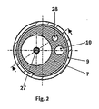
- Fig. 2 a section along the line II-II according to Fig.1
- Fig. 3 a section along the line III-III according to Fig. 2
- Fig. 1 the schematic structure of a modular common rail injection system
- Fig. 1 shows the schematic structure of a modular common rail injection system according to the present invention.
- fuel is sucked with a prefeed pump and from the high pressure pump 3 to the required System pressure brought and fed to the injection injector 4.
- the injector 4 consists of an injection nozzle 5, a throttle plate 6, a solenoid valve 7, a (not shown) with a high pressure accumulator equipped injector body 8 and a nozzle retaining nut 9, which holds the parts together.
- the solenoid valve 7 In the idle state, the solenoid valve 7 is closed, so that high-pressure fuel from the high-pressure bore 10 via the transverse groove 11 and the inlet throttle 12 flows into the control chamber 13 of the nozzle 5, the outflow from the control chamber 13 via the outlet throttle 14 but is blocked on the valve seat 15 of the solenoid valve 7 , The voltage applied in the control chamber 13 system pressure presses together with the force of the nozzle spring 16, the nozzle needle 17 in the nozzle needle seat 18, so that the injection holes 24 are closed.
- solenoid valve 7 If the solenoid valve 7 is operated by the solenoid 25 is controlled and the solenoid valve member 27 is lifted against the force of the solenoid valve spring 26 from the solenoid valve seat 15, it releases the flow through the solenoid valve seat 15, and fuel flows from the control chamber 13 through the outlet throttle 14, It sets a defined by the flow cross sections of inlet throttle 12 and outlet throttle 14 equilibrium pressure in the control chamber 13, which is so low that in the nozzle chamber 23 applied system pressure in the nozzle body 32 longitudinally displaceable guided nozzle needle 17 is able to open, so that the injection holes 24 are released and an injection takes place.
- an absolute pressure of 1-2 bar prevails, so that it comes through the Ab Kunststoffung the system pressure via inlet throttle 12, outlet throttle 14 and solenoid valve seat 15 to a strong heating of the fuel.
- electrical and magnetic losses act as additional heating, so it especially at high flow rates, as well as already preheated fuels (eg heavy oil) and can come at high electrical operating currents of the solenoid valve 7 to critical component loads.
- Fig. 2 shows the in Fig.1 indicated section through the injection injector 4. Here, in addition, the Spellerbohrung invention 28 is visible.
- Fig. 3 shows the in Fig. 2 specified section through the injection injector 4 with the invention Spülstofstoffmakers.
- the flushing quantity can be controlled via the flushing valve 30 and tempered in the heat exchanger 31.
- the diverted amount is passed via the flushing bore 28 directly to the solenoid valve seat 15, where the flushing quantity mixed with the exiting from the outlet throttle 14 control amount. Due to the large temperature difference between purge and control amount here is a significant cooling of the control amount, so that the adjusting temperature in the armature chamber 19 is much lower compared to a conventional injector without flushing.
Landscapes
- Engineering & Computer Science (AREA)
- Chemical & Material Sciences (AREA)
- Combustion & Propulsion (AREA)
- Mechanical Engineering (AREA)
- General Engineering & Computer Science (AREA)
- Physics & Mathematics (AREA)
- Fluid Mechanics (AREA)
- Manufacturing & Machinery (AREA)
- Electromagnetism (AREA)
- Fuel-Injection Apparatus (AREA)
Claims (5)
- Procédé pour injecter du carburant dans la chambre de combustion d'un moteur à combustion interne, dans lequel le carburant est acheminé par au moins une pompe de pré-alimentation (2) à partir d'un réservoir jusqu'à au moins une pompe à haute pression (3), et le carburant sous haute pression acheminé à partir de la pompe à haute pression (3) est délivré à l'injecteur (4), dans lequel l'injecteur (4) comporte une buse d'infection (5) avec une aiguille de buse (17) axialement mobile, laquelle aiguille de buse plonge dans une chambre de commande (13) pouvant être alimentée en carburant sous pression et dont la pression est commandée via une soupape de commande (7) qui ouvre ou ferme au moins un canal (14) d'alimentation ou de refoulement de carburant, dans lequel entre la pompe de pré-alimentation (2) et la pompe à haute pression (3), un volume partiel du carburant est dévié en tant que volume de purge, et est délivré à un canal de purge (28) de l'injecteur (4), dans lequel le volume de purge est directement délivré à la soupape de commande (13) de telle sorte que le volume de purge s'écoule au moins partiellement à travers la soupape de commande (13) et se mélange de préférence avec le carburant provenant du canal d'alimentation ou de refoulement (14), caractérisé en ce que le volume de purge est guidé par l'intermédiaire d'un échangeur de chaleur (31) afin de régler la température du volume de purge, dans lequel l'échangeur de chaleur refroidit le volume de purge pendant le fonctionnement afin de réduire la contrainte thermique et chauffe le volume de purge afin d'accélérer le démarrage du moteur.
- Procédé selon la revendication 1, caractérisé en ce que le volume de purge est délivré à la soupape de commande (7) dans la zone du siège de soupape (15) de l'organe de soupape.
- Procédé selon la revendication 1 ou 2, caractérisé en ce que la chambre d'armature de la soupape de commande (7) est traversée par le volume de purge.
- Procédé selon la revendication 1, 2 ou 3, caractérisé en ce que le volume de purge dévié entre la pompe de pré-alimentation (2) et la pompe à haute pression (3) est régulé, de préférence au moyen d'un papillon ou d'une soupape de purge (30).
- Procédé selon l'une quelconque des revendications 1 à 4, caractérisé en ce que le carburant est délivré à partir de la pompe de pré-alimentation (2) à une surpression de 5 à 10 bar.
Applications Claiming Priority (2)
| Application Number | Priority Date | Filing Date | Title |
|---|---|---|---|
| AT0129407A AT505666B1 (de) | 2007-08-20 | 2007-08-20 | Verfahren und vorrichtung zum einspritzen von kraftstoff in den brennraum einer brennkraftmaschine |
| PCT/AT2008/000293 WO2009023887A1 (fr) | 2007-08-20 | 2008-08-19 | Procédé et dispositif d'injection de carburant dans la chambre de combustion d'un moteur à combustion interne |
Publications (2)
| Publication Number | Publication Date |
|---|---|
| EP2183477A1 EP2183477A1 (fr) | 2010-05-12 |
| EP2183477B1 true EP2183477B1 (fr) | 2012-10-17 |
Family
ID=40090716
Family Applications (1)
| Application Number | Title | Priority Date | Filing Date |
|---|---|---|---|
| EP08782821A Not-in-force EP2183477B1 (fr) | 2007-08-20 | 2008-08-19 | Procede d'injection de carburant dans la chambre de combustion d'un moteur a combustion interne |
Country Status (8)
| Country | Link |
|---|---|
| US (1) | US8708247B2 (fr) |
| EP (1) | EP2183477B1 (fr) |
| JP (1) | JP2010537106A (fr) |
| KR (1) | KR101234161B1 (fr) |
| CN (1) | CN101965449A (fr) |
| AT (1) | AT505666B1 (fr) |
| RU (1) | RU2442016C2 (fr) |
| WO (1) | WO2009023887A1 (fr) |
Cited By (1)
| Publication number | Priority date | Publication date | Assignee | Title |
|---|---|---|---|---|
| DE102017208400A1 (de) | 2017-05-18 | 2018-11-22 | Robert Bosch Gmbh | Vorrichtung und Verfahren zum Einspritzen von Kraftstoff in einen Brennraum einer Brennkraftmaschine |
Families Citing this family (16)
| Publication number | Priority date | Publication date | Assignee | Title |
|---|---|---|---|---|
| US7937936B2 (en) * | 2007-01-16 | 2011-05-10 | Deere & Company | Vehicle exhaust component arrangement |
| DE102009027459A1 (de) * | 2009-07-03 | 2011-01-05 | Robert Bosch Gmbh | Kraftstoffeinspritzventil und Kraftstoffeinspritzsystem |
| DE102009027932A1 (de) * | 2009-07-22 | 2011-01-27 | Robert Bosch Gmbh | Kraftstoffinjektor und Kraftstoffeinspritzsystem |
| AT509405A1 (de) | 2010-01-19 | 2011-08-15 | Bosch Gmbh Robert | Verfahren zum temperieren eines injektors einer einspritzung für das einspritzen von kraftstoff in den brennraum einer brennkraftmaschine |
| DE102010062883A1 (de) * | 2010-09-14 | 2012-04-26 | Robert Bosch Gmbh | Verfahren zum Betreiben einer Einspritzanlage |
| HUE025828T2 (en) | 2010-10-20 | 2016-05-30 | Delphi Int Operations Luxembourg Sarl | Improved fuel injector |
| AT512422B1 (de) * | 2012-02-07 | 2016-01-15 | Bosch Gmbh Robert | Vorrichtung zum einspritzen von kraftstoff in den brennraum einer brennkraftmaschine |
| DE102012208075A1 (de) | 2012-05-15 | 2013-11-21 | Man Diesel & Turbo Se | Injektor für eine Kraftstoffversorgungsanlage einer Brennkraftmaschine sowie Kraftstoffversorgungsanlage |
| DE102012220025A1 (de) * | 2012-06-29 | 2014-01-02 | Robert Bosch Gmbh | Kraftstoffeinspritzventil für Brennkraftmaschinen |
| DE102013018177B4 (de) * | 2013-11-29 | 2016-01-28 | L'orange Gmbh | Kraftstoffinjektormodul sowie Kraftstoffinjektor und Prüfanordnung damit |
| AT516251B1 (de) * | 2015-01-07 | 2016-04-15 | Hoerbiger Kompressortech Hold | Brenngaszuführungs- und Zündvorrichtung für einen Gasmotor |
| AT516250B1 (de) * | 2015-01-07 | 2016-04-15 | Hoerbiger Kompressortech Hold | Brenngaszuführungs- und Zündvorrichtung für einen Gasmotor |
| DE102015001070A1 (de) * | 2015-01-29 | 2016-08-04 | Man Truck & Bus Ag | Temperierungsvorrichtung für ein Kraftstoffversorgungssystem eines Kraftfahrzeugs |
| DE102016211477A1 (de) * | 2016-06-27 | 2017-12-28 | Robert Bosch Gmbh | Düsenkörper für einen Kraftstoffinjektor |
| RU2722796C1 (ru) * | 2019-08-22 | 2020-06-03 | Владимир Александрович Шишков | Способ подачи лёгкого углеводородного топлива в двигатель внутреннего сгорания |
| CN112761827A (zh) * | 2021-01-27 | 2021-05-07 | 宁波盛煜智能科技有限公司 | 密封截面积可变的燃气喷嘴 |
Citations (1)
| Publication number | Priority date | Publication date | Assignee | Title |
|---|---|---|---|---|
| EP0304742A1 (fr) * | 1987-08-25 | 1989-03-01 | WEBER S.r.l. | Système d'injection de combustible à injecteurs commandés pour moteurs diesel |
Family Cites Families (14)
| Publication number | Priority date | Publication date | Assignee | Title |
|---|---|---|---|---|
| CH667698A5 (de) * | 1985-05-03 | 1988-10-31 | Sulzer Ag | Einrichtung zum betrieb einer kolbenbrennkraftmaschine mit einem brennstoff relativ hoher viskositaet. |
| JPH0219651A (ja) * | 1988-07-08 | 1990-01-23 | Toyota Motor Corp | 燃料噴射弁用圧電素子の加熱制御装置 |
| JPH0354358A (ja) * | 1989-07-21 | 1991-03-08 | Yamaha Motor Co Ltd | エンジンの高圧燃料噴射装置 |
| JP2976356B2 (ja) * | 1990-07-05 | 1999-11-10 | ヤマハ発動機株式会社 | エンジンの高圧燃料噴射装置 |
| US5148987A (en) | 1990-07-05 | 1992-09-22 | Yamaha Hatsudoki Kabushiki Kaisha | High pressure fuel injection device for engine |
| RU2015407C1 (ru) * | 1990-12-29 | 1994-06-30 | Макаренко Евгений Викторович | Двигатель внутреннего сгорания |
| US5335852A (en) * | 1993-01-28 | 1994-08-09 | Cummins Engine Company, Inc. | Lubrication oil controlled unit injector |
| AU6769598A (en) | 1997-03-31 | 1998-10-22 | Allied-Signal Inc. | Turbocharger integral fluid temperature management system |
| JP3791190B2 (ja) * | 1998-06-30 | 2006-06-28 | いすゞ自動車株式会社 | コモンレール式燃料噴射装置 |
| JP2002019651A (ja) | 1999-02-26 | 2002-01-23 | Tuner Kk | 車載用画像記録システム |
| RU2216643C2 (ru) * | 2002-01-28 | 2003-11-20 | Саратовский государственный технический университет | Топливная система дизельного двигателя |
| DE20310824U1 (de) | 2003-07-14 | 2004-11-18 | Winkelmann, Karlheinrich, Dipl.-Ing. (TH) | Verbrennungskraftmaschine mit Hochdruckeinspritzung eines flüssigen Kraftstoffgemisches |
| AT500773B8 (de) * | 2004-08-24 | 2007-02-15 | Bosch Gmbh Robert | Einspritzdüse für brennkraftmaschinen |
| RU45472U1 (ru) * | 2004-11-03 | 2005-05-10 | Буторов Сергей Михайлович | Система питания дизельного двигателя |
-
2007
- 2007-08-20 AT AT0129407A patent/AT505666B1/de not_active IP Right Cessation
-
2008
- 2008-08-19 JP JP2010521261A patent/JP2010537106A/ja active Pending
- 2008-08-19 WO PCT/AT2008/000293 patent/WO2009023887A1/fr not_active Ceased
- 2008-08-19 US US12/674,332 patent/US8708247B2/en not_active Expired - Fee Related
- 2008-08-19 CN CN2008801036836A patent/CN101965449A/zh active Pending
- 2008-08-19 KR KR1020107005986A patent/KR101234161B1/ko not_active Expired - Fee Related
- 2008-08-19 EP EP08782821A patent/EP2183477B1/fr not_active Not-in-force
- 2008-08-19 RU RU2010110548/06A patent/RU2442016C2/ru not_active IP Right Cessation
Patent Citations (1)
| Publication number | Priority date | Publication date | Assignee | Title |
|---|---|---|---|---|
| EP0304742A1 (fr) * | 1987-08-25 | 1989-03-01 | WEBER S.r.l. | Système d'injection de combustible à injecteurs commandés pour moteurs diesel |
Cited By (1)
| Publication number | Priority date | Publication date | Assignee | Title |
|---|---|---|---|---|
| DE102017208400A1 (de) | 2017-05-18 | 2018-11-22 | Robert Bosch Gmbh | Vorrichtung und Verfahren zum Einspritzen von Kraftstoff in einen Brennraum einer Brennkraftmaschine |
Also Published As
| Publication number | Publication date |
|---|---|
| KR101234161B1 (ko) | 2013-02-18 |
| AT505666A4 (de) | 2009-03-15 |
| US20110186647A1 (en) | 2011-08-04 |
| JP2010537106A (ja) | 2010-12-02 |
| CN101965449A (zh) | 2011-02-02 |
| EP2183477A1 (fr) | 2010-05-12 |
| KR20100090758A (ko) | 2010-08-17 |
| RU2010110548A (ru) | 2011-09-27 |
| WO2009023887A1 (fr) | 2009-02-26 |
| US8708247B2 (en) | 2014-04-29 |
| RU2442016C2 (ru) | 2012-02-10 |
| AT505666B1 (de) | 2009-03-15 |
Similar Documents
| Publication | Publication Date | Title |
|---|---|---|
| AT505666B1 (de) | Verfahren und vorrichtung zum einspritzen von kraftstoff in den brennraum einer brennkraftmaschine | |
| EP1781931B1 (fr) | Gicleur d'injection pour moteurs a combustion interne | |
| DE102004009792B3 (de) | Kraftstoffzuführeinrichtung zur Versorgung der Injektoren an Brennräumen einer Brennkraftmaschine mit Kraftstoff | |
| DE60311490T2 (de) | Flüssigkeitsgekühltes brennstoffeinspritzventil und methode zum betrieb eines flüssigkeitsgekühlten brennstoffeinspritzventils | |
| DE112009002378T5 (de) | Kühlprinzip für Treibstoffinjektor und Treibstoffsystem, das denselben verwendet | |
| DE19742180C2 (de) | Einspritzsystem für eine Brennkraftmaschine und Verfahren zum Regeln eines Einspritzsystems | |
| EP2526283B1 (fr) | Procédé pour thermoréguler un injecteur d'une injection pour l'injection de carburant dans la chambre de combustion d'un moteur à combustion interne | |
| EP1348072B1 (fr) | Procede, programme informatique et appareil de commande et/ou de reglage permettant d'exploiter un moteur a combustion interne et moteur a combustion interne | |
| DE3219612A1 (de) | Brennstoffabsperrvorrichtung fuer eine diesel-einspritzpumpe | |
| EP1209349B1 (fr) | Système d'injection de carburant avec préchauffage de carburant et soupape de régulation de pression refroidie avec du carburant | |
| DE4211651B4 (de) | Kraftstoffeinspritzeinrichtung, insbesondere Pumpedüse für Brennkraftmaschinen | |
| DE102007000095B4 (de) | Kraftstoffeinspritzelement | |
| AT501668B1 (de) | Steuerventil für eine einspritzdüse | |
| AT501914B1 (de) | Vorrichtung zum einspritzen von kraftstoff in den brennraum einer brennkraftmaschine | |
| AT512422B1 (de) | Vorrichtung zum einspritzen von kraftstoff in den brennraum einer brennkraftmaschine | |
| DE19738502A1 (de) | System zur Hochdruckerzeugung | |
| DE10056048A1 (de) | Kraftstoffeinspritzanlage für Brennkraftmaschinen mit Kraftstoffvorwärmung | |
| DE10005471A1 (de) | Kraftstoffversorgungsanlage für eine Brennkraftmaschine | |
| EP2273098B1 (fr) | Soupape d'injection de carburant et système d'injection de carburant | |
| EP2115291B1 (fr) | Soupape, dispositif et procédé de production d'une impulsion fluidique | |
| DE102012012890B4 (de) | Injektor | |
| DE19839579C1 (de) | Einspritzsystem | |
| DE102006000187A1 (de) | Fluideinspritzventil | |
| DE102016207521B4 (de) | Druckregelventil und Kraftstoffeinspritzsystem | |
| DE102013210231A1 (de) | Hochdruckpumpe für ein Kraftstoffeinspritzsystem sowie Verfahren zur Ermittlung der Kraftstofftemperatur in einer Hochdruckpumpe |
Legal Events
| Date | Code | Title | Description |
|---|---|---|---|
| PUAI | Public reference made under article 153(3) epc to a published international application that has entered the european phase |
Free format text: ORIGINAL CODE: 0009012 |
|
| 17P | Request for examination filed |
Effective date: 20100212 |
|
| AK | Designated contracting states |
Kind code of ref document: A1 Designated state(s): AT BE BG CH CY CZ DE DK EE ES FI FR GB GR HR HU IE IS IT LI LT LU LV MC MT NL NO PL PT RO SE SI SK TR |
|
| AX | Request for extension of the european patent |
Extension state: AL BA MK RS |
|
| RIN1 | Information on inventor provided before grant (corrected) |
Inventor name: HLOUSEK, JAROSLAV Inventor name: MEISL, CHRISTIAN Inventor name: BERNHAUPT, MARTIN |
|
| DAX | Request for extension of the european patent (deleted) | ||
| 17Q | First examination report despatched |
Effective date: 20110117 |
|
| GRAP | Despatch of communication of intention to grant a patent |
Free format text: ORIGINAL CODE: EPIDOSNIGR1 |
|
| GRAS | Grant fee paid |
Free format text: ORIGINAL CODE: EPIDOSNIGR3 |
|
| GRAA | (expected) grant |
Free format text: ORIGINAL CODE: 0009210 |
|
| AK | Designated contracting states |
Kind code of ref document: B1 Designated state(s): AT BE BG CH CY CZ DE DK EE ES FI FR GB GR HR HU IE IS IT LI LT LU LV MC MT NL NO PL PT RO SE SI SK TR |
|
| REG | Reference to a national code |
Ref country code: GB Ref legal event code: FG4D Free format text: NOT ENGLISH |
|
| REG | Reference to a national code |
Ref country code: CH Ref legal event code: EP Ref country code: CH Ref legal event code: NV Representative=s name: FIAMMENGHI-FIAMMENGHI |
|
| REG | Reference to a national code |
Ref country code: IE Ref legal event code: FG4D Free format text: LANGUAGE OF EP DOCUMENT: GERMAN |
|
| REG | Reference to a national code |
Ref country code: AT Ref legal event code: REF Ref document number: 580026 Country of ref document: AT Kind code of ref document: T Effective date: 20121115 |
|
| REG | Reference to a national code |
Ref country code: DE Ref legal event code: R096 Ref document number: 502008008429 Country of ref document: DE Effective date: 20121213 |
|
| REG | Reference to a national code |
Ref country code: NL Ref legal event code: VDEP Effective date: 20121017 |
|
| REG | Reference to a national code |
Ref country code: LT Ref legal event code: MG4D |
|
| PG25 | Lapsed in a contracting state [announced via postgrant information from national office to epo] |
Ref country code: ES Free format text: LAPSE BECAUSE OF FAILURE TO SUBMIT A TRANSLATION OF THE DESCRIPTION OR TO PAY THE FEE WITHIN THE PRESCRIBED TIME-LIMIT Effective date: 20130128 Ref country code: NO Free format text: LAPSE BECAUSE OF FAILURE TO SUBMIT A TRANSLATION OF THE DESCRIPTION OR TO PAY THE FEE WITHIN THE PRESCRIBED TIME-LIMIT Effective date: 20130117 Ref country code: HR Free format text: LAPSE BECAUSE OF FAILURE TO SUBMIT A TRANSLATION OF THE DESCRIPTION OR TO PAY THE FEE WITHIN THE PRESCRIBED TIME-LIMIT Effective date: 20121017 Ref country code: LT Free format text: LAPSE BECAUSE OF FAILURE TO SUBMIT A TRANSLATION OF THE DESCRIPTION OR TO PAY THE FEE WITHIN THE PRESCRIBED TIME-LIMIT Effective date: 20121017 Ref country code: NL Free format text: LAPSE BECAUSE OF FAILURE TO SUBMIT A TRANSLATION OF THE DESCRIPTION OR TO PAY THE FEE WITHIN THE PRESCRIBED TIME-LIMIT Effective date: 20121017 Ref country code: SE Free format text: LAPSE BECAUSE OF FAILURE TO SUBMIT A TRANSLATION OF THE DESCRIPTION OR TO PAY THE FEE WITHIN THE PRESCRIBED TIME-LIMIT Effective date: 20121017 Ref country code: IS Free format text: LAPSE BECAUSE OF FAILURE TO SUBMIT A TRANSLATION OF THE DESCRIPTION OR TO PAY THE FEE WITHIN THE PRESCRIBED TIME-LIMIT Effective date: 20130217 |
|
| PG25 | Lapsed in a contracting state [announced via postgrant information from national office to epo] |
Ref country code: PT Free format text: LAPSE BECAUSE OF FAILURE TO SUBMIT A TRANSLATION OF THE DESCRIPTION OR TO PAY THE FEE WITHIN THE PRESCRIBED TIME-LIMIT Effective date: 20130218 Ref country code: PL Free format text: LAPSE BECAUSE OF FAILURE TO SUBMIT A TRANSLATION OF THE DESCRIPTION OR TO PAY THE FEE WITHIN THE PRESCRIBED TIME-LIMIT Effective date: 20121017 Ref country code: SI Free format text: LAPSE BECAUSE OF FAILURE TO SUBMIT A TRANSLATION OF THE DESCRIPTION OR TO PAY THE FEE WITHIN THE PRESCRIBED TIME-LIMIT Effective date: 20121017 Ref country code: LV Free format text: LAPSE BECAUSE OF FAILURE TO SUBMIT A TRANSLATION OF THE DESCRIPTION OR TO PAY THE FEE WITHIN THE PRESCRIBED TIME-LIMIT Effective date: 20121017 Ref country code: GR Free format text: LAPSE BECAUSE OF FAILURE TO SUBMIT A TRANSLATION OF THE DESCRIPTION OR TO PAY THE FEE WITHIN THE PRESCRIBED TIME-LIMIT Effective date: 20130118 |
|
| PG25 | Lapsed in a contracting state [announced via postgrant information from national office to epo] |
Ref country code: EE Free format text: LAPSE BECAUSE OF FAILURE TO SUBMIT A TRANSLATION OF THE DESCRIPTION OR TO PAY THE FEE WITHIN THE PRESCRIBED TIME-LIMIT Effective date: 20121017 Ref country code: DK Free format text: LAPSE BECAUSE OF FAILURE TO SUBMIT A TRANSLATION OF THE DESCRIPTION OR TO PAY THE FEE WITHIN THE PRESCRIBED TIME-LIMIT Effective date: 20121017 Ref country code: SK Free format text: LAPSE BECAUSE OF FAILURE TO SUBMIT A TRANSLATION OF THE DESCRIPTION OR TO PAY THE FEE WITHIN THE PRESCRIBED TIME-LIMIT Effective date: 20121017 Ref country code: BG Free format text: LAPSE BECAUSE OF FAILURE TO SUBMIT A TRANSLATION OF THE DESCRIPTION OR TO PAY THE FEE WITHIN THE PRESCRIBED TIME-LIMIT Effective date: 20130117 Ref country code: CZ Free format text: LAPSE BECAUSE OF FAILURE TO SUBMIT A TRANSLATION OF THE DESCRIPTION OR TO PAY THE FEE WITHIN THE PRESCRIBED TIME-LIMIT Effective date: 20121017 |
|
| PLBE | No opposition filed within time limit |
Free format text: ORIGINAL CODE: 0009261 |
|
| STAA | Information on the status of an ep patent application or granted ep patent |
Free format text: STATUS: NO OPPOSITION FILED WITHIN TIME LIMIT |
|
| PG25 | Lapsed in a contracting state [announced via postgrant information from national office to epo] |
Ref country code: RO Free format text: LAPSE BECAUSE OF FAILURE TO SUBMIT A TRANSLATION OF THE DESCRIPTION OR TO PAY THE FEE WITHIN THE PRESCRIBED TIME-LIMIT Effective date: 20121017 |
|
| 26N | No opposition filed |
Effective date: 20130718 |
|
| REG | Reference to a national code |
Ref country code: DE Ref legal event code: R097 Ref document number: 502008008429 Country of ref document: DE Effective date: 20130718 |
|
| PG25 | Lapsed in a contracting state [announced via postgrant information from national office to epo] |
Ref country code: CY Free format text: LAPSE BECAUSE OF FAILURE TO SUBMIT A TRANSLATION OF THE DESCRIPTION OR TO PAY THE FEE WITHIN THE PRESCRIBED TIME-LIMIT Effective date: 20121017 |
|
| BERE | Be: lapsed |
Owner name: ROBERT BOSCH G.M.B.H. Effective date: 20130831 |
|
| GBPC | Gb: european patent ceased through non-payment of renewal fee |
Effective date: 20130819 |
|
| PG25 | Lapsed in a contracting state [announced via postgrant information from national office to epo] |
Ref country code: MC Free format text: LAPSE BECAUSE OF FAILURE TO SUBMIT A TRANSLATION OF THE DESCRIPTION OR TO PAY THE FEE WITHIN THE PRESCRIBED TIME-LIMIT Effective date: 20121017 |
|
| REG | Reference to a national code |
Ref country code: IE Ref legal event code: MM4A |
|
| REG | Reference to a national code |
Ref country code: FR Ref legal event code: ST Effective date: 20140430 |
|
| PG25 | Lapsed in a contracting state [announced via postgrant information from national office to epo] |
Ref country code: BE Free format text: LAPSE BECAUSE OF NON-PAYMENT OF DUE FEES Effective date: 20130831 |
|
| PG25 | Lapsed in a contracting state [announced via postgrant information from national office to epo] |
Ref country code: GB Free format text: LAPSE BECAUSE OF NON-PAYMENT OF DUE FEES Effective date: 20130819 Ref country code: IE Free format text: LAPSE BECAUSE OF NON-PAYMENT OF DUE FEES Effective date: 20130819 |
|
| PG25 | Lapsed in a contracting state [announced via postgrant information from national office to epo] |
Ref country code: FR Free format text: LAPSE BECAUSE OF NON-PAYMENT OF DUE FEES Effective date: 20130902 |
|
| REG | Reference to a national code |
Ref country code: AT Ref legal event code: MM01 Ref document number: 580026 Country of ref document: AT Kind code of ref document: T Effective date: 20130819 |
|
| PG25 | Lapsed in a contracting state [announced via postgrant information from national office to epo] |
Ref country code: AT Free format text: LAPSE BECAUSE OF NON-PAYMENT OF DUE FEES Effective date: 20130819 |
|
| PG25 | Lapsed in a contracting state [announced via postgrant information from national office to epo] |
Ref country code: MT Free format text: LAPSE BECAUSE OF FAILURE TO SUBMIT A TRANSLATION OF THE DESCRIPTION OR TO PAY THE FEE WITHIN THE PRESCRIBED TIME-LIMIT Effective date: 20121017 Ref country code: TR Free format text: LAPSE BECAUSE OF FAILURE TO SUBMIT A TRANSLATION OF THE DESCRIPTION OR TO PAY THE FEE WITHIN THE PRESCRIBED TIME-LIMIT Effective date: 20121017 |
|
| PG25 | Lapsed in a contracting state [announced via postgrant information from national office to epo] |
Ref country code: LU Free format text: LAPSE BECAUSE OF NON-PAYMENT OF DUE FEES Effective date: 20130819 Ref country code: HU Free format text: LAPSE BECAUSE OF FAILURE TO SUBMIT A TRANSLATION OF THE DESCRIPTION OR TO PAY THE FEE WITHIN THE PRESCRIBED TIME-LIMIT; INVALID AB INITIO Effective date: 20080819 |
|
| PGFP | Annual fee paid to national office [announced via postgrant information from national office to epo] |
Ref country code: CH Payment date: 20150824 Year of fee payment: 8 |
|
| REG | Reference to a national code |
Ref country code: CH Ref legal event code: PL |
|
| PG25 | Lapsed in a contracting state [announced via postgrant information from national office to epo] |
Ref country code: LI Free format text: LAPSE BECAUSE OF NON-PAYMENT OF DUE FEES Effective date: 20160831 Ref country code: CH Free format text: LAPSE BECAUSE OF NON-PAYMENT OF DUE FEES Effective date: 20160831 |
|
| PGFP | Annual fee paid to national office [announced via postgrant information from national office to epo] |
Ref country code: IT Payment date: 20220831 Year of fee payment: 15 Ref country code: FI Payment date: 20220818 Year of fee payment: 15 |
|
| PGFP | Annual fee paid to national office [announced via postgrant information from national office to epo] |
Ref country code: DE Payment date: 20221025 Year of fee payment: 15 |
|
| REG | Reference to a national code |
Ref country code: DE Ref legal event code: R119 Ref document number: 502008008429 Country of ref document: DE |
|
| PG25 | Lapsed in a contracting state [announced via postgrant information from national office to epo] |
Ref country code: FI Free format text: LAPSE BECAUSE OF NON-PAYMENT OF DUE FEES Effective date: 20230819 |
|
| PG25 | Lapsed in a contracting state [announced via postgrant information from national office to epo] |
Ref country code: IT Free format text: LAPSE BECAUSE OF NON-PAYMENT OF DUE FEES Effective date: 20230819 Ref country code: DE Free format text: LAPSE BECAUSE OF NON-PAYMENT OF DUE FEES Effective date: 20240301 |