EP2184377A1 - Appareil de fabrication d'une bande d'acier plaquée par trempage à chaud - Google Patents
Appareil de fabrication d'une bande d'acier plaquée par trempage à chaud Download PDFInfo
- Publication number
- EP2184377A1 EP2184377A1 EP08829357A EP08829357A EP2184377A1 EP 2184377 A1 EP2184377 A1 EP 2184377A1 EP 08829357 A EP08829357 A EP 08829357A EP 08829357 A EP08829357 A EP 08829357A EP 2184377 A1 EP2184377 A1 EP 2184377A1
- Authority
- EP
- European Patent Office
- Prior art keywords
- steel strip
- strip
- steel
- submersed
- molten metal
- Prior art date
- Legal status (The legal status is an assumption and is not a legal conclusion. Google has not performed a legal analysis and makes no representation as to the accuracy of the status listed.)
- Withdrawn
Links
Images



Classifications
-
- C—CHEMISTRY; METALLURGY
- C23—COATING METALLIC MATERIAL; COATING MATERIAL WITH METALLIC MATERIAL; CHEMICAL SURFACE TREATMENT; DIFFUSION TREATMENT OF METALLIC MATERIAL; COATING BY VACUUM EVAPORATION, BY SPUTTERING, BY ION IMPLANTATION OR BY CHEMICAL VAPOUR DEPOSITION, IN GENERAL; INHIBITING CORROSION OF METALLIC MATERIAL OR INCRUSTATION IN GENERAL
- C23C—COATING METALLIC MATERIAL; COATING MATERIAL WITH METALLIC MATERIAL; SURFACE TREATMENT OF METALLIC MATERIAL BY DIFFUSION INTO THE SURFACE, BY CHEMICAL CONVERSION OR SUBSTITUTION; COATING BY VACUUM EVAPORATION, BY SPUTTERING, BY ION IMPLANTATION OR BY CHEMICAL VAPOUR DEPOSITION, IN GENERAL
- C23C2/00—Hot-dipping or immersion processes for applying the coating material in the molten state without affecting the shape; Apparatus therefor
- C23C2/14—Removing excess of molten coatings; Controlling or regulating the coating thickness
- C23C2/16—Removing excess of molten coatings; Controlling or regulating the coating thickness using fluids under pressure, e.g. air knives
- C23C2/18—Removing excess of molten coatings from elongated material
- C23C2/20—Strips; Plates
-
- C—CHEMISTRY; METALLURGY
- C23—COATING METALLIC MATERIAL; COATING MATERIAL WITH METALLIC MATERIAL; CHEMICAL SURFACE TREATMENT; DIFFUSION TREATMENT OF METALLIC MATERIAL; COATING BY VACUUM EVAPORATION, BY SPUTTERING, BY ION IMPLANTATION OR BY CHEMICAL VAPOUR DEPOSITION, IN GENERAL; INHIBITING CORROSION OF METALLIC MATERIAL OR INCRUSTATION IN GENERAL
- C23C—COATING METALLIC MATERIAL; COATING MATERIAL WITH METALLIC MATERIAL; SURFACE TREATMENT OF METALLIC MATERIAL BY DIFFUSION INTO THE SURFACE, BY CHEMICAL CONVERSION OR SUBSTITUTION; COATING BY VACUUM EVAPORATION, BY SPUTTERING, BY ION IMPLANTATION OR BY CHEMICAL VAPOUR DEPOSITION, IN GENERAL
- C23C2/00—Hot-dipping or immersion processes for applying the coating material in the molten state without affecting the shape; Apparatus therefor
- C23C2/003—Apparatus
- C23C2/0034—Details related to elements immersed in bath
- C23C2/00342—Moving elements, e.g. pumps or mixers
- C23C2/00344—Means for moving substrates, e.g. immersed rollers or immersed bearings
-
- C—CHEMISTRY; METALLURGY
- C23—COATING METALLIC MATERIAL; COATING MATERIAL WITH METALLIC MATERIAL; CHEMICAL SURFACE TREATMENT; DIFFUSION TREATMENT OF METALLIC MATERIAL; COATING BY VACUUM EVAPORATION, BY SPUTTERING, BY ION IMPLANTATION OR BY CHEMICAL VAPOUR DEPOSITION, IN GENERAL; INHIBITING CORROSION OF METALLIC MATERIAL OR INCRUSTATION IN GENERAL
- C23C—COATING METALLIC MATERIAL; COATING MATERIAL WITH METALLIC MATERIAL; SURFACE TREATMENT OF METALLIC MATERIAL BY DIFFUSION INTO THE SURFACE, BY CHEMICAL CONVERSION OR SUBSTITUTION; COATING BY VACUUM EVAPORATION, BY SPUTTERING, BY ION IMPLANTATION OR BY CHEMICAL VAPOUR DEPOSITION, IN GENERAL
- C23C2/00—Hot-dipping or immersion processes for applying the coating material in the molten state without affecting the shape; Apparatus therefor
- C23C2/003—Apparatus
- C23C2/0035—Means for continuously moving substrate through, into or out of the bath
Definitions
- the present invention relates to an apparatus for producing a hot-dip metal coated steel strip in a hot-dip metal coating process, the apparatus being configured to reduce splashing of a molten metal.
- a gas wiping device is typically arranged, the gas wiping device being configured to control the amount of a molten metal coated (coating weight) on a steel strip 2 by blowing a pressurized gas from gas wiping nozzles 3 to the steel strip to remove an excess amount of the molten metal, the gas wiping nozzles 3 extending in the direction of the width of the steel strip and being arranged on both sides so as to face the steel strip 2, in order that the molten metal sticking to the surface of the steel strip uniformly has a predetermined thickness in the transverse and longitudinal directions, the blowing step being performed after the steps of immersing the steel strip 2 in the molten metal 7 filled in a coating bath 8, changing the travel direction using a sink roll 6, and drawing the steel strip 2 in the vertical direction.
- submersed support rolls 5 are usually arranged above the sink roll 6 and below the molten metal surface.
- support rolls 4 outside the bath are arranged above the gas wiping nozzles 3, as needed.
- the gas wiping nozzles 3 are usually longer than the width of the steel strip, i.e., each extend beyond the ends of the steel strip 2 in the width direction, in order to correspond steel strips with various widths and the displacement in the width direction in drawing the steel strip.
- splashing in which the molten metal dropping toward the lower portion of the steel strip is spattered, due to the turbulence of a jet impinging on the steel strip 2 occurs, leading to a reduction in the surface quality of the steel strip.
- the threading speed may be increased.
- the coating weight is controlled by the gas wiping method, the initial amount of the molten metal applied to the steel strip immediately after the steel strip passes through the coating bath is increased with increasing line speed due to the viscosity of the molten metal.
- the wiping gas pressure is forced to be set at a higher level. This results in a significant increase in the amount of splash, thereby reducing the surface quality.
- a method for reducing an excess amount of molten metal sticking to a steel strip between a coating bath and wiping nozzles to some extent to reduce the initial amount of the molten metal sticking to the steel strip immediately after the steel strip passes through the coating bath is disclosed as follows.
- Patent Document 1 Japanese Unexamined Patent Application Publication No. 2004-76082 discloses an apparatus including molten-metal-reducing members arranged on both sides of a steel strip and between support rolls and gas wiping nozzles in a coating bath so as to face the steel strip, in which an excess amount of molten metal is removed, and then gas wiping is performed to control the coating thickness.
- Each of the molten-metal-reducing members preferably has a rectangular shape, a shape having an entry portion in which the distance between the member and the corresponding surface of the steel strip increases with decreasing distance from the lower end of the member, or a columnar shape.
- the molten-metal-reducing members are most preferably located so as to cross the surface of the molten metal.
- Patent Document 2 Japanese Unexamined Patent Application Publication No. 2005-15837 discloses a hot-dip metal coating apparatus including a blade wiping device having blades arranged on both sides of the steel strip and tilted with respect to the steel strip, the blade wiping device being located on and above the surface of a molten metal, in which an excess amount of molten metal is removed, and then gas wiping is performed to control the coating thickness.
- a portion of each blade closest to the steel strip has a round shape with a diameter of 30 mm.
- the apparatus in the case where the molten-metal-reducing members are located above the molten metal surface or so as to cross the molten metal surface, the apparatus has the following disadvantages:
- the molten metal finally removed by gas wiping flows down to form pools between the steel strip and the molten-metal-reducing members.
- the reduction effect is low because of a short distance between the pools and the gas wiping nozzles.
- the solidified metal sticking to the molten-metal-reducing members adheres to the steel strip, thereby forming surface defects.
- the inventors have come to the conclusion that in the case where a molten-metal-reducing member for removing an excess amount of molten metal is arranged between a sink roll and a gas wiping portion, the best position of the molten-metal-reducing member arranged is below the molten metal surface because an excess amount of the molten metal cannot be reduced due to the short distance between the pools and the gas wiping portion as described above.
- the molten-metal-reducing member having a known cross section provides a low effect of reducing the molten metal.
- the inventors have conducted intensive studies on, for example, the shape of the molten-metal-reducing member for removing an excess amount of the molten metal sticking to the steel strip and have conceived rectifying plates serving as the molten-metal-reducing member on the basis of the findings, each of the rectifying plates (baffle plates) having a portion covering 1/4 or more of the periphery of a corresponding one of the submersed support rolls near to the surface of the molten metal and having a portion facing the steel strip. This has led to the completion of the invention having the following characteristics.
- the coating thickness can be adjusted after removing an excess amount of the molten metal sticking to the steel strip, thereby significantly reducing the amount of splashing.
- an increase in threading speed results in a significant increase in the amount of splashing.
- the occurrence of splashing can be suppressed even at a significantly increased threading speed. Therefore, the apparatus according to the present invention produces a surface defect-free hot-dip metal coated steel strip with high productivity.
- FIG. 2 shows an apparatus for producing a hot-dip metal coated steel strip according to an embodiment of the present invention.
- reference numeral 1 denotes rectifying plates.
- the rectifying plates 1 are arranged on the respective sides of a steel strip 2, above submersed support rolls 5, and below the surface of the molten metal.
- Each of the rectifying plates 1 has a portion (roll-covering portion) covering the periphery of a corresponding one of the submersed support rolls 5 while not being in contact with the corresponding submersed support roll 5 and a portion (steel-strip-facing portion) facing the steel strip while not being in contact with the steel strip.
- Each of the steel-strip-facing portions is arranged above a corresponding one of the roll-covering portions. The bottom of each steel-strip-facing portion is connected to the steel-strip-side end of the corresponding roll-covering portion.
- Each of the submersed support rolls 5 is rotated in such a manner that the rotation direction of a portion thereof closest to the steel strip is equal to the travel direction of the steel strip.
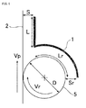
- Fig. 3 illustrates exemplary cross-sectional shapes of the rectifying plates 1 arranged in the apparatus shown in Fig. 2 and flows of the molten metal around the rectifying plates 1.
- Reference numeral 11 denotes flows caused by the submersed support rolls 5.
- Reference numeral 12 denotes flows caused by the steel strip 2.
- Reference numeral 13 denotes flows induced by the flows 11.
- the arrangement of the rectifying plates 1 above the submersed support rolls 5 below the molten metal surface results in the generation of the flows 11 due to the submersed support rolls 5 between the submersed support rolls 5 and the rectifying plates 1.
- the generation of the flows 11 results in the generation of the forced flows 13 between steel strip 2 and the rectifying plates 1 in the direction opposite to the travel direction of the steel strip 2 even when the flows 12 are generated, thus significantly reducing the accompanying flows 12. This results in a reduction in an excess amount of molten metal sticking to the steel strip drawn from the coating bath.
- the portion of each rectifying plate 1 covering the corresponding submersed support roll 5 needs to have a length sufficient to cover 1/4 or more (25% or more) of the periphery of a corresponding one of the submersed support rolls 5 near to the molten metal surface.
- the longer portion covering the corresponding submersed support roll 5 improves the effect as long as the portion is not in contact with the steel strip.
- the portion may cover 1/4 or more (25% or more) of the periphery of the corresponding submersed support roll 5 near to the molten metal surface and less than 100% of the periphery of the corresponding submersed support roll 5 near to the molten metal surface and is not in contact with the steel strip 2.
- the length of each rectifying plate 1 covering the corresponding submersed support roll 5 defined here is the length of the arc of the periphery of the submersed support roll 5 on which the rectifying plate 1 is projected when the rectifying plate 1 is projected toward the center of the submersed support roll 5 in a cross section perpendicular to the center line of the submersed support roll 5.
- the distance between each rectifying plate 1 and a corresponding one of the submersed support rolls 5 is preferably 100 mm or less and more preferably 50 mm or less. A distance exceeding 100 mm weakens the accompanying flows 11, so that the flows 13 are not generated, thereby reducing the effect of decreasing an excess amount of molten metal sticking to the steel strip. A distance of 50 mm or less results in the suppression of the flows reducing an excess amount of the molten metal sticking to the steel strip, thereby further enhancing the effect of reducing an excess amount of the molten metal sticking to the steel strip.
- the distance between each rectifying plate 1 and the corresponding submersed support roll 5 may be reduced as long as the rectifying plate 1 is not in contact with the submersed support roll 5.
- the distance between each rectifying plate 1 and the corresponding submersed support roll 5 may be larger than 0 mm.
- the distance between the rectifying plates 1 and the steel strip 2 is preferably 100 mm or less and more preferably 50 mm or less. At a distance exceeding 100 mm, the flows 13 propagating in the direction opposite to the travel direction of the steel strip 2 do not affect the accompanying flows 12 caused by the travel of the steel strip 2, thus reducing the effect of decreasing an excess amount of the molten metal sticking to the steel strip. A distance of 50 mm or less results in the suppression of the flows caused by the steel strip, thus further enhancing the effect of reducing an excess amount of the molten metal sticking to the steel strip.
- the distance between the rectifying plates 1 and the steel strip 2 may be reduced as long as the rectifying plates 1 are not in contact with the steel strip 2.
- the distance between each rectifying plate 1 and the corresponding submersed support roll 5 may be larger than 0 mm.
- each rectifying plate 1 and the corresponding submersed support roll 5 It is not necessary to maintain a constant distance between each rectifying plate 1 and the corresponding submersed support roll 5. Also, it is not necessarily to maintain a constant distance between the rectifying plates 1 and the steel strip 2.
- the shape of the portions of the rectifying plates 1 covering the submersed support rolls 5 is not limited to an arc. Furthermore, the portions of the rectifying plates 1 facing the steel strip 2 may not be arranged in parallel with the steel strip.
- each rectifying plate 1 is preferably located at a position 100 mm or less apart from the molten metal surface. If the distance from the molten metal surface exceeds 100 mm, the accompanying flows 12 due to the travel of the steel strip 2 develops above the rectifying plates 1, thereby reducing the effect of decreasing an excess amount of the molten metal sticking to the steel strip. If the top of at least one of the rectifying plates 1 is located above the molten metal surface, the excess molten metal is wiped to attach the top of the at least one of the rectifying plates 1, thus disadvantageously damaging the steel strip.
- the circumferential speed Vr of the support rolls synchronizes with the speed Vp of the steel strip.
- Each of the distance S between the steel strip 2 and the rectifying plates 1 and the distance Sr between each submersed support roll 5 and the corresponding rectifying plates 1 is 100 mm or less.
- the arc length Lr of the periphery of each submersed support roll 5 near to the molten metal surface, the periphery being covered with a corresponding one of the rectifying plates 1, is ⁇ D/4 or more.
- An increase in the left-hand side of the expression (1) can result in improvement in the effect of reducing an excess amount of the molten metal sticking to the steel strip.
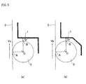
- each of the rectifying plates 1 covering the submersed support rolls 5 does not have the arc shape as shown in Fig. 3 but has, for example, an inverted L shape in which a horizontal portion is connected to a vertical portion as shown in Fig. 5(a) or a shape in which an inclined portion is arranged between a horizontal portion and a vertical portion as shown in Fig. 5(b) , the portion has a low pressure loss to reduce the effect.
- each rectifying plate 1 facing the steel strip 2 does not have the shape parallel to the steel strip surface as shown in Fig. 3 but has, for example, a shape tilted with respect to the steel strip surface in the travel direction as shown in Fig. 6
- the effect can be roughly calculated by replacing S with the minimum distance S' between the steel strip 2 and the rectifying plates 1 as a representative distance and replacing L with the projected length of the steel-strip-facing portion of the rectifying plate 1 in the travel direction of the steel strip when the steel-strip-facing portions of the rectifying plate 1 is projected on the steel strip surface in the expression (1).
- the apparatus for producing a hot-dip metal coated steel strip shown in Fig. 2 was installed in a continuous hot-dip galvanizing line. An experiment for producing a hot-dip galvanized steel strip was performed.
- the rectifying plates 1 were attached to frames of the submersed support rolls 5 and thus could not be moved during the operation of the line.
- the amount of offset of the submersed support rolls arranged on both sides of the steel strip 2 was 200 mm in the vertical direction.
- the distance between the molten metal surface and the top of the submersed support roll closer to the molten metal surface was 80 mm.
- the distance Sr between each of the submersed support rolls 5 and a corresponding one of the rectifying plates 1 was 20 mm.
- the distance S between the steel strip 2 and the rectifying plates 1 was fixed to 30 mm.
- the steel-strip-facing portion of each rectifying plate had a tilted shape in which the top was 20 mm and the bottom was 30 mm apart from the steel strip.
- the portions of the rectifying plates 1 parallel to the steel strip extended so as to be 30 mm apart from the surface of molten zinc.
- the portions of the rectifying plates 1 covering the submersed support rolls 5 had an arc shape.
- the length of the rectifying plates 1 in the direction of the width of the steel strip was 2,000 mm comparable to that of the gas wiping nozzles.
- the submersed support rolls had a diameter D of 400 mm.
- Conditions for producing the hot-dip metal coated steel strip were as follows: the slit gap of each gas wiping nozzle: 0.8 mm, gas wiping nozzle-steel strip distance: 7 mm, nozzle height from the molten zinc surface: 400 mm, and the temperature of the molten zinc bath: 460°C.
- the steel strip to be produced had a thickness of 0.8 mm, a width of 1.2 m, and a coating weight of 45 g/m 2 per side.
- Table 1 shows other production conditions, the length Lr of the portion of each rectifying plate 1 covering the periphery of the corresponding submersed support roll 5 near to the molten zinc surface, the minimum distance S between the steel strip and the rectifying plates, the length L of the steel-strip-facing portion of the corresponding rectifying plate, the minimum distance Sr between each submersed support roll and the corresponding rectifying plate, and the amount of splash serving as a product quality index.
- the amount of splash is defined as the ratio of the length of the steel strip determined as a strip having splash defects to the length of the steel strip fed under such production conditions.
- the resulting steel strips contained practically negligible splash defects.
- Examples 1 and 2 were different in the length Lr of the portion of each rectifying plate 1 covering the periphery of the corresponding submersed support roll 5 near to the molten zinc surface. In both cases, the significant effect of reducing splashing was provided compared with Comparative Example 1.
- Example 3 the steel-strip-facing portion of each rectifying plate 1 had the tilted shape in which the top was 20 mm and the bottom was 30 mm apart from the steel strip. In this case, the significant effect of reducing splashing was provided compared with Comparative Example 1.
- Example 4 and Comparative Example 2 the threading speed was set to as high as 4.0 m/s. In Comparative Example 2, splashing occurred frequently; hence, the operation could not be performed. In contrast, in Example 4, the operation could be performed at a high quality level compared with that of the current operation at 2.5 m/s.
- the apparatus of the present invention can be used as equipment for producing a hot-dip metal coated steel strip having excellent appearance by reducing the occurrence of splashing.
- the apparatus of the present invention can inhibit the occurrence of splashing even at high-speed threading and thus can be used as an apparatus for producing a hot-dip metal coated steel strip having excellent appearance with high productivity.
Landscapes
- Chemical & Material Sciences (AREA)
- Chemical Kinetics & Catalysis (AREA)
- Engineering & Computer Science (AREA)
- Materials Engineering (AREA)
- Mechanical Engineering (AREA)
- Metallurgy (AREA)
- Organic Chemistry (AREA)
- Coating With Molten Metal (AREA)
Applications Claiming Priority (2)
| Application Number | Priority Date | Filing Date | Title |
|---|---|---|---|
| JP2007229781A JP5549050B2 (ja) | 2007-09-05 | 2007-09-05 | 溶融金属めっき鋼帯の製造装置 |
| PCT/JP2008/065927 WO2009031599A1 (fr) | 2007-09-05 | 2008-08-28 | Appareil de fabrication d'une bande d'acier plaquée par trempage à chaud |
Publications (2)
| Publication Number | Publication Date |
|---|---|
| EP2184377A1 true EP2184377A1 (fr) | 2010-05-12 |
| EP2184377A4 EP2184377A4 (fr) | 2011-02-16 |
Family
ID=40428913
Family Applications (1)
| Application Number | Title | Priority Date | Filing Date |
|---|---|---|---|
| EP08829357A Withdrawn EP2184377A4 (fr) | 2007-09-05 | 2008-08-28 | Appareil de fabrication d'une bande d'acier plaquée par trempage à chaud |
Country Status (6)
| Country | Link |
|---|---|
| US (1) | US20100175615A1 (fr) |
| EP (1) | EP2184377A4 (fr) |
| JP (1) | JP5549050B2 (fr) |
| KR (1) | KR101191692B1 (fr) |
| CN (1) | CN101796209B (fr) |
| WO (1) | WO2009031599A1 (fr) |
Families Citing this family (10)
| Publication number | Priority date | Publication date | Assignee | Title |
|---|---|---|---|---|
| JP5444744B2 (ja) * | 2009-02-10 | 2014-03-19 | Jfeスチール株式会社 | 溶融金属めっき鋼帯の製造装置 |
| JP5375150B2 (ja) * | 2009-02-13 | 2013-12-25 | Jfeスチール株式会社 | 溶融金属めっき鋼帯の製造装置 |
| JP5466521B2 (ja) * | 2010-01-26 | 2014-04-09 | 昭和電工株式会社 | 磁気記録媒体の製造装置 |
| MX2013006985A (es) * | 2011-01-14 | 2013-07-29 | Nippon Steel & Sumitomo Metal Corp | Miembro regulador de flujo de tanque de revestimiento por inmersion en caliente y sistema de revestimiento por inmersion en caliente continuo. |
| JP6044669B2 (ja) * | 2015-04-20 | 2016-12-14 | Jfeスチール株式会社 | 溶融金属めっき鋼帯の製造装置及び製造方法 |
| CN106256442A (zh) * | 2015-06-18 | 2016-12-28 | 深圳市堃琦鑫华股份有限公司 | 一种涂料涂布工艺 |
| KR102182280B1 (ko) * | 2016-03-29 | 2020-11-24 | 닛폰세이테츠 가부시키가이샤 | 연속 용융 금속 도금 장치 및 연속 용융 금속 도금 방법 |
| EP3604601A4 (fr) * | 2017-03-31 | 2020-02-05 | JFE Steel Corporation | Procédé et dispositif de production d'une bande d'acier plaquée de métal par immersion à chaud |
| US11384419B2 (en) * | 2019-08-30 | 2022-07-12 | Micromaierials Llc | Apparatus and methods for depositing molten metal onto a foil substrate |
| CN116618437B (zh) * | 2023-04-13 | 2026-01-02 | 北京首钢冷轧薄板有限公司 | 减少重卷机组入口带钢划伤的装置及重卷机组 |
Family Cites Families (5)
| Publication number | Priority date | Publication date | Assignee | Title |
|---|---|---|---|---|
| JPH076048B2 (ja) * | 1989-12-25 | 1995-01-25 | 住友金属工業株式会社 | ボトムドロス巻上げ防止方法および装置 |
| FR2816638B1 (fr) * | 2000-11-10 | 2003-09-19 | Lorraine Laminage | Installation de revetement au trempe d'une bande metallique notamment d'une bande d'acier |
| JP3772804B2 (ja) * | 2002-08-15 | 2006-05-10 | Jfeスチール株式会社 | 溶融めっき金属帯の製造装置及び製造方法 |
| JP2005015837A (ja) * | 2003-06-25 | 2005-01-20 | Mitsubishi Heavy Ind Ltd | 溶融金属メッキ装置 |
| WO2009017209A1 (fr) * | 2007-07-30 | 2009-02-05 | Jfe Steel Corporation | Equipement de fabrication d'un feuillard d'acier en bobine plaqué de métal liquide et procédé de fabrication d'un feuillard d'acier en bobine plaqué de métal liquide |
-
2007
- 2007-09-05 JP JP2007229781A patent/JP5549050B2/ja not_active Expired - Fee Related
-
2008
- 2008-08-28 WO PCT/JP2008/065927 patent/WO2009031599A1/fr not_active Ceased
- 2008-08-28 CN CN2008801049357A patent/CN101796209B/zh not_active Expired - Fee Related
- 2008-08-28 KR KR1020107004867A patent/KR101191692B1/ko not_active Expired - Fee Related
- 2008-08-28 US US12/676,157 patent/US20100175615A1/en not_active Abandoned
- 2008-08-28 EP EP08829357A patent/EP2184377A4/fr not_active Withdrawn
Also Published As
| Publication number | Publication date |
|---|---|
| CN101796209B (zh) | 2012-06-13 |
| JP5549050B2 (ja) | 2014-07-16 |
| WO2009031599A1 (fr) | 2009-03-12 |
| US20100175615A1 (en) | 2010-07-15 |
| EP2184377A4 (fr) | 2011-02-16 |
| CN101796209A (zh) | 2010-08-04 |
| JP2009062563A (ja) | 2009-03-26 |
| KR101191692B1 (ko) | 2012-10-16 |
| KR20100040954A (ko) | 2010-04-21 |
Similar Documents
| Publication | Publication Date | Title |
|---|---|---|
| EP2196554B1 (fr) | Appareil et procédé de fabrication d'une bande d'acier revêtue d'un métal à l'état fondu | |
| US20100175615A1 (en) | Apparatus for producing hot-dip metal coated steel strip | |
| KR20200044428A (ko) | 용융도금강판의 냉각장치 | |
| JP5470932B2 (ja) | 溶融金属めっき鋼帯製造設備及び溶融金属めっき鋼帯の製造方法 | |
| JP6888376B2 (ja) | ガスワイピングノズル | |
| JP5418550B2 (ja) | 溶融金属めっき鋼帯の製造方法 | |
| EP3486351A1 (fr) | Procédé de fabrication d'une bande d'acier revêtue de métal fondu et équipement de placage de métal fondu continu | |
| JP3772804B2 (ja) | 溶融めっき金属帯の製造装置及び製造方法 | |
| JP5444744B2 (ja) | 溶融金属めっき鋼帯の製造装置 | |
| JP3617473B2 (ja) | 溶融亜鉛系めっき鋼板の製造方法 | |
| JP5444730B2 (ja) | 溶融金属めっき鋼帯製造装置 | |
| JP5444705B2 (ja) | 溶融金属めっき鋼帯製造装置 | |
| JP5375150B2 (ja) | 溶融金属めっき鋼帯の製造装置 | |
| JPH042756A (ja) | 連続溶融めっきにおけるガスワイピング方法 | |
| WO2009017209A1 (fr) | Equipement de fabrication d'un feuillard d'acier en bobine plaqué de métal liquide et procédé de fabrication d'un feuillard d'acier en bobine plaqué de métal liquide | |
| JP4816105B2 (ja) | 溶融金属めっき鋼帯の製造方法 | |
| JP4998696B2 (ja) | 溶融金属めっき鋼帯の製造装置及び溶融金属めっき鋼帯の製造方法 | |
| JP3762722B2 (ja) | 溶融めっき鋼板の冷却装置および冷却方法 | |
| JP5194613B2 (ja) | 溶融金属めっき鋼帯の製造装置及び溶融金属めっき鋼帯の製造方法 | |
| JP6870659B2 (ja) | 溶融金属めっき設備用ガスワイピングノズル、溶融金属めっきのガスワイピング方法、及び溶融金属めっき鋼板の製造方法 | |
| JPH11279736A (ja) | 厚目付けに適したガスワイピング方法 | |
| JP5194612B2 (ja) | 溶融金属めっき鋼帯の製造装置及び溶融金属めっき鋼帯の製造方法 | |
| JP4765641B2 (ja) | 溶融金属めっき鋼帯の製造方法 | |
| JPH04285146A (ja) | 連続溶融金属めっき装置 | |
| JPH0247247A (ja) | 溶融めっきのエッジオーバーコート防止方法 |
Legal Events
| Date | Code | Title | Description |
|---|---|---|---|
| PUAI | Public reference made under article 153(3) epc to a published international application that has entered the european phase |
Free format text: ORIGINAL CODE: 0009012 |
|
| 17P | Request for examination filed |
Effective date: 20100211 |
|
| AK | Designated contracting states |
Kind code of ref document: A1 Designated state(s): AT BE BG CH CY CZ DE DK EE ES FI FR GB GR HR HU IE IS IT LI LT LU LV MC MT NL NO PL PT RO SE SI SK TR |
|
| AX | Request for extension of the european patent |
Extension state: AL BA MK RS |
|
| DAX | Request for extension of the european patent (deleted) | ||
| A4 | Supplementary search report drawn up and despatched |
Effective date: 20110119 |
|
| STAA | Information on the status of an ep patent application or granted ep patent |
Free format text: STATUS: EXAMINATION IS IN PROGRESS |
|
| 17Q | First examination report despatched |
Effective date: 20170607 |
|
| STAA | Information on the status of an ep patent application or granted ep patent |
Free format text: STATUS: THE APPLICATION IS DEEMED TO BE WITHDRAWN |
|
| 18D | Application deemed to be withdrawn |
Effective date: 20180823 |