EP2184512A1 - Actionneur avec capteur de charge intégré - Google Patents
Actionneur avec capteur de charge intégré Download PDFInfo
- Publication number
- EP2184512A1 EP2184512A1 EP08792745A EP08792745A EP2184512A1 EP 2184512 A1 EP2184512 A1 EP 2184512A1 EP 08792745 A EP08792745 A EP 08792745A EP 08792745 A EP08792745 A EP 08792745A EP 2184512 A1 EP2184512 A1 EP 2184512A1
- Authority
- EP
- European Patent Office
- Prior art keywords
- screw shaft
- base body
- load sensor
- actuator
- bed
- Prior art date
- Legal status (The legal status is an assumption and is not a legal conclusion. Google has not performed a legal analysis and makes no representation as to the accuracy of the status listed.)
- Withdrawn
Links
Images


Classifications
-
- A—HUMAN NECESSITIES
- A47—FURNITURE; DOMESTIC ARTICLES OR APPLIANCES; COFFEE MILLS; SPICE MILLS; SUCTION CLEANERS IN GENERAL
- A47C—CHAIRS; SOFAS; BEDS
- A47C19/00—Bedsteads
- A47C19/04—Extensible bedsteads, e.g. with adjustment of length, width, height
-
- F—MECHANICAL ENGINEERING; LIGHTING; HEATING; WEAPONS; BLASTING
- F16—ENGINEERING ELEMENTS AND UNITS; GENERAL MEASURES FOR PRODUCING AND MAINTAINING EFFECTIVE FUNCTIONING OF MACHINES OR INSTALLATIONS; THERMAL INSULATION IN GENERAL
- F16H—GEARING
- F16H25/00—Gearings comprising primarily only cams, cam-followers and screw-and-nut mechanisms
- F16H25/18—Gearings comprising primarily only cams, cam-followers and screw-and-nut mechanisms for conveying or interconverting oscillating or reciprocating motions
- F16H25/20—Screw mechanisms
- F16H25/2021—Screw mechanisms with means for avoiding overloading
-
- A—HUMAN NECESSITIES
- A61—MEDICAL OR VETERINARY SCIENCE; HYGIENE
- A61G—TRANSPORT, PERSONAL CONVEYANCES, OR ACCOMMODATION SPECIALLY ADAPTED FOR PATIENTS OR DISABLED PERSONS; OPERATING TABLES OR CHAIRS; CHAIRS FOR DENTISTRY; FUNERAL DEVICES
- A61G7/00—Beds specially adapted for nursing; Devices for lifting patients or disabled persons
- A61G7/05—Parts, details or accessories of beds
-
- A—HUMAN NECESSITIES
- A61—MEDICAL OR VETERINARY SCIENCE; HYGIENE
- A61G—TRANSPORT, PERSONAL CONVEYANCES, OR ACCOMMODATION SPECIALLY ADAPTED FOR PATIENTS OR DISABLED PERSONS; OPERATING TABLES OR CHAIRS; CHAIRS FOR DENTISTRY; FUNERAL DEVICES
- A61G7/00—Beds specially adapted for nursing; Devices for lifting patients or disabled persons
- A61G7/05—Parts, details or accessories of beds
- A61G7/0527—Weighing devices
-
- F—MECHANICAL ENGINEERING; LIGHTING; HEATING; WEAPONS; BLASTING
- F16—ENGINEERING ELEMENTS AND UNITS; GENERAL MEASURES FOR PRODUCING AND MAINTAINING EFFECTIVE FUNCTIONING OF MACHINES OR INSTALLATIONS; THERMAL INSULATION IN GENERAL
- F16H—GEARING
- F16H25/00—Gearings comprising primarily only cams, cam-followers and screw-and-nut mechanisms
- F16H25/18—Gearings comprising primarily only cams, cam-followers and screw-and-nut mechanisms for conveying or interconverting oscillating or reciprocating motions
- F16H25/20—Screw mechanisms
-
- G—PHYSICS
- G01—MEASURING; TESTING
- G01G—WEIGHING
- G01G19/00—Weighing apparatus or methods adapted for special purposes not provided for in the preceding groups
- G01G19/44—Weighing apparatus or methods adapted for special purposes not provided for in the preceding groups for weighing persons
- G01G19/445—Weighing apparatus or methods adapted for special purposes not provided for in the preceding groups for weighing persons in a horizontal position
-
- G—PHYSICS
- G01—MEASURING; TESTING
- G01G—WEIGHING
- G01G19/00—Weighing apparatus or methods adapted for special purposes not provided for in the preceding groups
- G01G19/52—Weighing apparatus combined with other objects, e.g. furniture
-
- G—PHYSICS
- G01—MEASURING; TESTING
- G01G—WEIGHING
- G01G23/00—Auxiliary devices for weighing apparatus
- G01G23/18—Indicating devices, e.g. for remote indication; Recording devices; Scales, e.g. graduated
- G01G23/36—Indicating the weight by electrical means, e.g. using photoelectric cells
- G01G23/37—Indicating the weight by electrical means, e.g. using photoelectric cells involving digital counting
- G01G23/3728—Indicating the weight by electrical means, e.g. using photoelectric cells involving digital counting with wireless means
-
- G—PHYSICS
- G01—MEASURING; TESTING
- G01G—WEIGHING
- G01G3/00—Weighing apparatus characterised by the use of elastically-deformable members, e.g. spring balances
- G01G3/12—Weighing apparatus characterised by the use of elastically-deformable members, e.g. spring balances wherein the weighing element is in the form of a solid body stressed by pressure or tension during weighing
- G01G3/14—Weighing apparatus characterised by the use of elastically-deformable members, e.g. spring balances wherein the weighing element is in the form of a solid body stressed by pressure or tension during weighing measuring variations of electrical resistance
- G01G3/1402—Special supports with preselected places to mount the resistance strain gauges; Mounting of supports
- G01G3/141—Special supports with preselected places to mount the resistance strain gauges; Mounting of supports the supports being disc or ring shaped
Definitions
- the present invention relates to a load sensor-containing actuator.
- An actuator in which one end side of a screw shaft is rotatably supported by a base body; a female threaded member is engaged with the screw shaft; and an actuation rod body fixed to the female threaded member can advance and retreat in the axial direction of the screw shaft, is widely used in a lifting mechanism for the bottom of a bed, etc.
- Patent Document 1 Recently for example as disclosed in Patent Document 1, it is practiced to install load sensors in all the legs of a bed so that the loads on the bed bottom can be detected as the body weight and movements of the patient to be referred to for care, nursing, etc.
- the loads measured can be used to detect and notify that the user of a bed such as an elderly person gets off from the bed bottom, for preventing the occurrence of any accident, etc.
- Means for detecting a load on a bed bottom include various means such as detecting the change of pressure in an envelope caused by a load.
- a load sensor separate from a bed as in Patent Document 1 or installed outside has the following problems.
- the present invention proposes a load sensor-containing actuator in which one end side of a screw shaft is rotatably supported by a base body; a female threaded member is engaged with the screw shaft; and an actuation rod body fixed to the female threaded member can advance and retreat in the axial direction of the screw shaft, wherein the base body is provided with a thrust bearing coaxially with the screw shaft and an actuation cylinder supporting the one end side of the screw shaft in the axial direction via the thrust bearing; a detection cylinder is provided between the actuation cylinder and a support member for the base body; and a strain gauge is attached to the outside surface of the detection cylinder.
- this invention proposes the abovementioned constitution, wherein a detection means for detecting the signal of the strain gauge is installed in the base body; and electric wiring is used to deliver the detected signal to outside the base body.
- this invention proposes the abovementioned constitution, wherein a detection means for detecting the signal of the strain gauge is installed in the base body; and a wireless communication means is provided in the detection means, to deliver the detected signal by wireless communication to outside the base body.
- this invention proposes the abovementioned constitution, wherein the support member can be attached to and detached from the base body.
- this invention proposes the abovementioned constitution, wherein a small diameter portion is formed on the one end side of the screw shaft; and the thrust bearing is disposed at the small diameter portion, to transmit the load in the axial direction.
- the load transmitted from the actuation rod body to the screw shaft via the female threaded member is transmitted to the actuation cylinder via the thrust bearing, to compress the detection cylinder disposed between the actuation cylinder and the support member in the axial direction.
- the detection cylinder compressed in the axial direction is elastically deformed to bulge out in the middle portion like a barrel, and the strain gauge fixed on the outside surface is deformed in response to the elastic deformation.
- the load applied via the actuation rod body can be measured in reference to the deformation of the strain gauge.
- the detection cylinder with the strain gauge attached thereto, and the thrust bearing and the actuation cylinder respectively transmitting the load to the detection cylinder can be compactly accommodated in the base body, since they are coaxial with the screw shaft.
- the load sensor-containing actuator of this invention can be used in a lifting mechanism of a bed, etc., since the actuator can have the same external form and other constitution as those of the conventional actuator, except that the former contains a load sensor in the base body. In this case, the actuator can measure the load on the bed as a component integral with the bed.
- the detected signal of the strain gauge contained in the actuator can be delivered by electric wiring via a detection means such as an amplifier to outside the actuator or by wireless communication to outside the actuator, to be applied to a load measuring means.
- a detection means such as an amplifier to outside the actuator or by wireless communication to outside the actuator, to be applied to a load measuring means.
- the electric wiring can be led out from the same lead-out portion as that for motor wiring, etc. and it is not necessary to install any special lead-out portion.
- the load sensor and the actuator are integrated, the adjustment of the load sensor as a system can be completed when the load sensor-containing actuator per se is produced, and the calibration is not required when the load sensor-containing actuator is installed in a bed, etc. Thus, the process and cost of assembling into a bed, etc. can be reduced.
- the support member can be attached to and detached from the base body in the load sensor-containing actuator of this invention, the support member having the detection cylinder and the strain gauge can be exchanged by the corresponding set suitable for each load range required. Therefore, the actuator can be easily changed to suit any of variously different load ranges. Furthermore, if a support member with a support rib projected instead of the detection cylinder is attached to the base body instead, an actuator identical in external form but not containing a load sensor can be easily constituted.
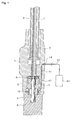
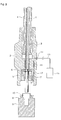
- Figs. 1 through 4 are illustrative vertical sectional views showing embodiments of the load sensor-containing actuator of this invention.
- Symbol 1 denotes a screw shaft, and one end side of the screw shaft 1 is rotatably supported by a base body 2.
- a female threaded member 3 is engaged with the screw shaft 1, and an action rod body 4 is fixed to the female threaded member 3.
- the action rod body 4 can advance and retreat in the axial direction of the screw shaft 1.
- the base body 2 is hatched in the drawings, but the hatched portion does not necessarily indicate a solid portion, and can also be a hollow portion as appropriate.
- a rotatable radial bearing restrained in the radial direction only can be installed at any appropriate place between the base body 2 and the screw shaft 1.
- Symbol 5 denotes a small diameter portion formed on the one end side of the screw shaft 1, and a thrust bearing 6 is disposed at the small diameter portion 5, to transmit the load of the screw shaft 1 from the upper face of the recess formed around the small diameter portion 5 to the upper member of the thrust bearing 6. Further, below the lower member of the thrust bearing 6, an actuation cylinder 7 is provided below the lower member of the thrust bearing 6, an actuation cylinder 7 is provided below the lower member of the thrust bearing 6, an actuation cylinder 7 is provided below the lower member of the thrust bearing 6, an actuation cylinder 7 is provided below the lower member of the thrust bearing 6, an actuation cylinder 7 is provided below the lower member of the thrust bearing 6, an actuation cylinder 7 is provided below the lower member of the thrust bearing 6, an actuation cylinder 7 is provided below the lower member of the thrust bearing 6, an actuation cylinder 7 is provided below the lower member of the thrust bearing 6, an actuation cylinder 7 is provided below the lower member of the thrust bearing 6, an actuation cylinder 7 is provided below
- Symbol 8 denotes a support member, and the support member 8 can be attached to the rear side of the base body 2 as shown in Figs. 1 and 2 .
- the attaching mechanism can be, for example, a binding mechanism using fasteners such as screws or using threaded engagement, etc.
- a detection cylinder 9 is projected, and when the support member is attached as shown in Fig. 1 , the detection cylinder 9 is disposed outside the screw shaft 1 coaxially with the screw shaft 1, and the top face of the detection cylinder 9 contacts the bottom surface of the actuation cylinder 7.
- a strain gauge 10 is attached to the outside surface of the detection cylinder 9.
- Symbol 11 denotes a circuit board, and the circuit board 11 is connected with the signal wiring 12 extending from the strain gauge 10 and contains a detection means for, for example, amplifying the detected signal of the strain gauge 10 as one of the functions of the circuit board 11.
- the output wiring 13 from the circuit board 11 is led outside the base body 1 from the lead-out portion having a cord cap 14 and connected with a controller 15 containing a load measuring means as one of the functions of the controller.
- the controller 15 and the circuit board 11 can also have such functions as the drive control and rotational speed detection of a motor not shown in the drawings, in addition to the abovementioned function of detecting the load concerning the strain gauge 10. Meanwhile, the circuit board 11 can also be omitted if the functions of the circuit board can be contained in the controller 15.
- the detection cylinder 9 with the strain gauge 10 attached thereto, and the actuation cylinder 7 and the thrust bearing 6 for transmitting the load to the detection cylinder 9 are coaxial with the screw shaft 1, they can be compactly accommodated in the base body 2.
- the load sensor-containing actuator of this invention can have the same external form and other constitution as those of the conventional actuator, except that the former contains a load sensor in the base body 2. Therefore, the actuator of this invention can be used in a lifting mechanism of a bed, etc. in the same mode as that of the conventional actuator.
- the load transmitted from the actuation rod body 4 to the screw shaft 1 via the female threaded member 3 is transmitted to the actuation cylinder 7 via the thrust bearing 6, to compress in the axial direction of the screw shaft 1, the detection cylinder 9 disposed between the actuation cylinder 7 and the support member 8.
- the detection cylinder 9 compressed in the axial direction is elastically deformed to bulge out in the middle portion like a barrel, and the strain gauge 10 is deformed in response to the elastic deformation.
- the load applied via the actuation rod body 4 can be measured in reference to the deformation of the strain gauge 10. That is, in the case of this embodiment, the load from the bottom of the bed can be delivered as a detected signal via the circuit board 11 and the output wiring 13, to be measured by the controller 15 installed outside the actuator.
- the signal detected by the strain gauge 10 contained in the actuator is delivered outside the actuator by the output wiring 13 via the lead-out portion having the cord cap 14. If the lead-out portion of the feeder and the signal wiring to a motor not shown in the drawings and to the circuit board 11 can be used as the lead-out portion, it is not necessary to install a lead-out portion special for the actuator.
- circuit board 11 or the like can be provided with a wireless communication means, so that the signal detected by the strain gauge 10 can be sent to outside the actuator by wireless communication, to be measured by a load measuring means such as the controller 15, etc.
- the load sensor-containing actuator of this invention is used for a bed, the load sensor for measuring the load on the bed and the cable extending from the load sensor are not exposed on the floor of the sickroom. Therefore, environment resistant performance such as waterproof property, dustproof property, impact resistance and vibration resistance can be easily secured.
- the support member 8 can be attached to and detached from the base body 2, the support member 8 can be replaced by a support member 8 having a detection cylinder 9 and a strain gauge 10 suitable for each load range. Therefore, the actuator can be easily changed to suit many different load ranges.
- a support member 8' having a support rib 16 projected instead of the detection cylinder can be attached to the base body 2, to easily provide an actuator with the same external form but not containing a load sensor.
- the load sensor-containing actuator of this invention can be used in a bottom lifting mechanism of a bed in a hospital, a facility for the elderly, or a general household, etc.
- the actuator of this invention can be installed integrally with a bed and used as a means for measuring the body weight of the user on the bed or for detecting such information as the body motion of the user. Having the abovementioned advantages, this invention is highly industrially applicable.
- the load sensor-containing actuator of this invention can also be used as a load measurable actuator in a medical instrument, furniture, etc.
- the load sensor-containing actuator of this invention can also be used as a load measuring instrument in which an actuation rod body can advance and retreat.
Landscapes
- Physics & Mathematics (AREA)
- General Physics & Mathematics (AREA)
- Engineering & Computer Science (AREA)
- General Engineering & Computer Science (AREA)
- Health & Medical Sciences (AREA)
- General Health & Medical Sciences (AREA)
- Veterinary Medicine (AREA)
- Public Health (AREA)
- Animal Behavior & Ethology (AREA)
- Life Sciences & Earth Sciences (AREA)
- Nursing (AREA)
- Mechanical Engineering (AREA)
- Computer Networks & Wireless Communication (AREA)
- Invalid Beds And Related Equipment (AREA)
- Transmission Devices (AREA)
- Force Measurement Appropriate To Specific Purposes (AREA)
Applications Claiming Priority (2)
| Application Number | Priority Date | Filing Date | Title |
|---|---|---|---|
| JP2007294963A JP5116147B2 (ja) | 2007-11-13 | 2007-11-13 | 荷重センサ内蔵アクチュエータ |
| PCT/JP2008/065199 WO2009063673A1 (fr) | 2007-11-13 | 2008-08-26 | Actionneur avec capteur de charge intégré |
Publications (2)
| Publication Number | Publication Date |
|---|---|
| EP2184512A1 true EP2184512A1 (fr) | 2010-05-12 |
| EP2184512A4 EP2184512A4 (fr) | 2011-09-07 |
Family
ID=40638527
Family Applications (1)
| Application Number | Title | Priority Date | Filing Date |
|---|---|---|---|
| EP08792745A Withdrawn EP2184512A4 (fr) | 2007-11-13 | 2008-08-26 | Actionneur avec capteur de charge intégré |
Country Status (7)
| Country | Link |
|---|---|
| US (1) | US8127620B2 (fr) |
| EP (1) | EP2184512A4 (fr) |
| JP (1) | JP5116147B2 (fr) |
| KR (1) | KR101469705B1 (fr) |
| CN (1) | CN101702930B (fr) |
| TW (1) | TW200920341A (fr) |
| WO (1) | WO2009063673A1 (fr) |
Cited By (5)
| Publication number | Priority date | Publication date | Assignee | Title |
|---|---|---|---|---|
| WO2012035560A1 (fr) * | 2010-09-17 | 2012-03-22 | Kanika Bansal | Lit d'hôpital à usages multiples |
| WO2012096391A1 (fr) * | 2011-01-13 | 2012-07-19 | Sintokogio, Ltd. | Système à cylindre électrique |
| WO2012139577A1 (fr) * | 2011-04-12 | 2012-10-18 | Linak A/S | Système d'actionneur électrique |
| WO2013038729A1 (fr) * | 2011-09-14 | 2013-03-21 | Sintokogio, Ltd. | Cylindre électrique et système à cylindre électrique |
| EP4105516A1 (fr) * | 2021-06-18 | 2022-12-21 | Goodrich Actuation Systems Limited | Découplage de charge pour aile repliable |
Families Citing this family (11)
| Publication number | Priority date | Publication date | Assignee | Title |
|---|---|---|---|---|
| EP2341252B1 (fr) * | 2009-12-30 | 2012-04-25 | AGUSTAWESTLAND S.p.A. | Avion |
| JP5699617B2 (ja) * | 2011-01-13 | 2015-04-15 | 新東工業株式会社 | 電動シリンダ及び電動シリンダシステム |
| BR112015024038B1 (pt) | 2013-03-22 | 2022-07-26 | Moog Inc | Estrutura de detecção de carga |
| JP6194754B2 (ja) * | 2013-10-29 | 2017-09-13 | アイシン精機株式会社 | ベッド用荷重検出装置 |
| JP5741748B2 (ja) * | 2014-04-10 | 2015-07-01 | 新東工業株式会社 | 電動シリンダ |
| JP6637715B2 (ja) * | 2014-12-28 | 2020-01-29 | パラマウントベッド株式会社 | 寝台用センサ及びそれを組み込んだ寝台 |
| JP6757155B2 (ja) * | 2015-04-02 | 2020-09-16 | パラマウントベッド株式会社 | 状態判定装置 |
| JP2017209698A (ja) * | 2016-05-24 | 2017-11-30 | 日本デイトンプログレス株式会社 | プレス装置及びそれに使用されるバッキングプレート |
| CN108071649A (zh) * | 2016-11-16 | 2018-05-25 | 孙愉后 | 紧固件 |
| US10975940B2 (en) * | 2017-08-24 | 2021-04-13 | Eaton Intelligent Power Limited | Actuator and method |
| WO2020076426A1 (fr) * | 2018-10-08 | 2020-04-16 | UDP Labs, Inc. | Systèmes et procédés d'utilisation de la gravité pour déterminer des informations spécifiques à un sujet |
Family Cites Families (16)
| Publication number | Priority date | Publication date | Assignee | Title |
|---|---|---|---|---|
| US4307799A (en) * | 1979-12-05 | 1981-12-29 | Andco Actuator Products, Inc. | Linear actuator |
| JPH0351546Y2 (fr) * | 1986-01-07 | 1991-11-06 | ||
| JP2507933B2 (ja) * | 1987-04-02 | 1996-06-19 | 三菱マテリアル株式会社 | ボ−ルネジ |
| JP2513403Y2 (ja) * | 1988-05-16 | 1996-10-09 | 株式会社椿本チエイン | 電動直線作動機の過負荷検知機構 |
| US5058439A (en) * | 1990-06-06 | 1991-10-22 | The Babcock & Wilcox Company | Ut socket assembly |
| JPH06276631A (ja) * | 1992-05-26 | 1994-09-30 | Yasuda Seisakusho Co Ltd | 張力検出器及びこれを用いた延線方法 |
| JP2729724B2 (ja) * | 1992-06-19 | 1998-03-18 | 佐藤工業株式会社 | 全天候型仮設屋根の自動上昇装置 |
| JP3093745B2 (ja) | 1998-03-30 | 2000-10-03 | 大和製衡株式会社 | 寝台装置 |
| JP3632004B2 (ja) * | 2001-04-27 | 2005-03-23 | 三菱重工業株式会社 | ボールねじ装置、及び同装置を備えた射出成形機、及びボールねじ装置制御方法 |
| TW521031B (en) * | 2001-04-27 | 2003-02-21 | Mitsubishi Heavy Ind Ltd | Ball screw device and injection molding machine incorporating the same |
| JP3719663B2 (ja) * | 2002-03-27 | 2005-11-24 | 日信工業株式会社 | 電気式ディスクブレーキ |
| US6870341B2 (en) * | 2002-04-15 | 2005-03-22 | Paramount Bed Co., Ltd. | Method of controlling the coordinative lifting of bottom sections of lying furniture such as a bed |
| JP3862668B2 (ja) * | 2002-04-15 | 2006-12-27 | パラマウントベッド株式会社 | ベッド等の仰臥台におけるボトムの連動昇降制御方法 |
| WO2006007713A1 (fr) * | 2004-07-20 | 2006-01-26 | Robin Lee Dickson | Actionneur lineaire |
| JP3664406B1 (ja) * | 2004-09-16 | 2005-06-29 | サイエンティフィックテクノロジーズ有限会社 | 負荷感応推力増幅機構を持つ動力伝達方法及び装置 |
| US7654158B2 (en) * | 2007-01-12 | 2010-02-02 | Nabors Global Holdings Ltd. | Real time torque system |
-
2007
- 2007-11-13 JP JP2007294963A patent/JP5116147B2/ja active Active
-
2008
- 2008-08-26 WO PCT/JP2008/065199 patent/WO2009063673A1/fr not_active Ceased
- 2008-08-26 KR KR1020097018385A patent/KR101469705B1/ko not_active Expired - Fee Related
- 2008-08-26 US US12/742,156 patent/US8127620B2/en active Active
- 2008-08-26 CN CN200880007728XA patent/CN101702930B/zh active Active
- 2008-08-26 EP EP08792745A patent/EP2184512A4/fr not_active Withdrawn
- 2008-10-07 TW TW097138550A patent/TW200920341A/zh not_active IP Right Cessation
Cited By (8)
| Publication number | Priority date | Publication date | Assignee | Title |
|---|---|---|---|---|
| WO2012035560A1 (fr) * | 2010-09-17 | 2012-03-22 | Kanika Bansal | Lit d'hôpital à usages multiples |
| WO2012096391A1 (fr) * | 2011-01-13 | 2012-07-19 | Sintokogio, Ltd. | Système à cylindre électrique |
| US9415557B2 (en) | 2011-01-13 | 2016-08-16 | Sintokogio, Ltd. | Electric cylinder system |
| WO2012139577A1 (fr) * | 2011-04-12 | 2012-10-18 | Linak A/S | Système d'actionneur électrique |
| WO2013038729A1 (fr) * | 2011-09-14 | 2013-03-21 | Sintokogio, Ltd. | Cylindre électrique et système à cylindre électrique |
| US9614418B2 (en) | 2011-09-14 | 2017-04-04 | Sintokogio, Ltd. | Electric cylinder and electric cylinder system |
| EP4105516A1 (fr) * | 2021-06-18 | 2022-12-21 | Goodrich Actuation Systems Limited | Découplage de charge pour aile repliable |
| US12296949B2 (en) | 2021-06-18 | 2025-05-13 | Goodrich Actuation Systems Limited | Load decouple for folding wing |
Also Published As
| Publication number | Publication date |
|---|---|
| KR20100093474A (ko) | 2010-08-25 |
| US20100313682A1 (en) | 2010-12-16 |
| US8127620B2 (en) | 2012-03-06 |
| TWI357325B (fr) | 2012-02-01 |
| WO2009063673A1 (fr) | 2009-05-22 |
| JP2009121566A (ja) | 2009-06-04 |
| EP2184512A4 (fr) | 2011-09-07 |
| TW200920341A (en) | 2009-05-16 |
| CN101702930A (zh) | 2010-05-05 |
| CN101702930B (zh) | 2012-08-22 |
| JP5116147B2 (ja) | 2013-01-09 |
| KR101469705B1 (ko) | 2014-12-05 |
Similar Documents
| Publication | Publication Date | Title |
|---|---|---|
| US8127620B2 (en) | Load sensor-containing actuator | |
| CN204246381U (zh) | 带负荷检测功能的床以及床用负荷检测器 | |
| EP2175759B1 (fr) | Meuble de repos tel qu'un lit ou une chaise | |
| JP6265556B2 (ja) | 荷重検出機能付きベッド及びベッド用荷重検出器 | |
| EP2696834B1 (fr) | Système d'actionneur électrique | |
| US20060277683A1 (en) | Hospital patient support | |
| EP2696759B1 (fr) | Système actionneur électrique | |
| US20120247228A1 (en) | Device and Method for Detecting a Collision of a Displaceable Furniture Part and an Obstacle | |
| CN105377208A (zh) | 带负荷检测功能的床以及床用负荷检测器 | |
| EP1902237B1 (fr) | Ensemble actionneur et lit | |
| JP2020049280A (ja) | 寝台用センサ及びそれを組み込んだ寝台 | |
| JP5435598B2 (ja) | 荷重センサ内蔵アクチュエータ | |
| KR101492093B1 (ko) | 배회 방지시스템을 구비한 침대장치 | |
| CN111692959B (zh) | 一种位移测量装置 | |
| KR101979210B1 (ko) | 배회 감지기를 구비한 침대 | |
| JP2006266894A (ja) | ベッドの荷重検出器 | |
| JP5965717B2 (ja) | 荷重検出機能付きベッド及び荷重検出器 | |
| KR20050018133A (ko) | 다기능 좌변기 | |
| CA2537601A1 (fr) | Support de patient d'hopital | |
| JP2013242149A (ja) | 荷重検出機能付きベッド及び荷重検出器 |
Legal Events
| Date | Code | Title | Description |
|---|---|---|---|
| PUAI | Public reference made under article 153(3) epc to a published international application that has entered the european phase |
Free format text: ORIGINAL CODE: 0009012 |
|
| 17P | Request for examination filed |
Effective date: 20090804 |
|
| AK | Designated contracting states |
Kind code of ref document: A1 Designated state(s): AT BE BG CH CY CZ DE DK EE ES FI FR GB GR HR HU IE IS IT LI LT LU LV MC MT NL NO PL PT RO SE SI SK TR |
|
| AX | Request for extension of the european patent |
Extension state: AL BA MK RS |
|
| DAX | Request for extension of the european patent (deleted) | ||
| A4 | Supplementary search report drawn up and despatched |
Effective date: 20110804 |
|
| RIC1 | Information provided on ipc code assigned before grant |
Ipc: A47C 19/04 20060101ALI20110729BHEP Ipc: F16H 25/20 20060101AFI20110729BHEP Ipc: G01G 19/52 20060101ALI20110729BHEP Ipc: A61G 7/05 20060101ALI20110729BHEP |
|
| 17Q | First examination report despatched |
Effective date: 20130128 |
|
| STAA | Information on the status of an ep patent application or granted ep patent |
Free format text: STATUS: THE APPLICATION IS DEEMED TO BE WITHDRAWN |
|
| 18D | Application deemed to be withdrawn |
Effective date: 20180301 |